EP0597425B1 - Structure for cooling an integrated circuit - Google Patents
Structure for cooling an integrated circuit Download PDFInfo
- Publication number
- EP0597425B1 EP0597425B1 EP93118087A EP93118087A EP0597425B1 EP 0597425 B1 EP0597425 B1 EP 0597425B1 EP 93118087 A EP93118087 A EP 93118087A EP 93118087 A EP93118087 A EP 93118087A EP 0597425 B1 EP0597425 B1 EP 0597425B1
- Authority
- EP
- European Patent Office
- Prior art keywords
- heat conductor
- passageway
- hollow cylindrical
- heat
- cold plate
- Prior art date
- Legal status (The legal status is an assumption and is not a legal conclusion. Google has not performed a legal analysis and makes no representation as to the accuracy of the status listed.)
- Expired - Lifetime
Links
Images


Classifications
-
- H—ELECTRICITY
- H10—SEMICONDUCTOR DEVICES; ELECTRIC SOLID-STATE DEVICES NOT OTHERWISE PROVIDED FOR
- H10W—GENERIC PACKAGES, INTERCONNECTIONS, CONNECTORS OR OTHER CONSTRUCTIONAL DETAILS OF DEVICES COVERED BY CLASS H10
- H10W40/00—Arrangements for thermal protection or thermal control
- H10W40/40—Arrangements for thermal protection or thermal control involving heat exchange by flowing fluids
- H10W40/47—Arrangements for thermal protection or thermal control involving heat exchange by flowing fluids by flowing liquids, e.g. forced water cooling
- H10W40/475—Arrangements for thermal protection or thermal control involving heat exchange by flowing fluids by flowing liquids, e.g. forced water cooling using jet impingement
-
- H—ELECTRICITY
- H10—SEMICONDUCTOR DEVICES; ELECTRIC SOLID-STATE DEVICES NOT OTHERWISE PROVIDED FOR
- H10W—GENERIC PACKAGES, INTERCONNECTIONS, CONNECTORS OR OTHER CONSTRUCTIONAL DETAILS OF DEVICES COVERED BY CLASS H10
- H10W40/00—Arrangements for thermal protection or thermal control
- H10W40/70—Fillings or auxiliary members in containers or in encapsulations for thermal protection or control
- H10W40/77—Auxiliary members characterised by their shape
-
- H—ELECTRICITY
- H10—SEMICONDUCTOR DEVICES; ELECTRIC SOLID-STATE DEVICES NOT OTHERWISE PROVIDED FOR
- H10W—GENERIC PACKAGES, INTERCONNECTIONS, CONNECTORS OR OTHER CONSTRUCTIONAL DETAILS OF DEVICES COVERED BY CLASS H10
- H10W72/00—Interconnections or connectors in packages
- H10W72/851—Dispositions of multiple connectors or interconnections
- H10W72/874—On different surfaces
- H10W72/877—Bump connectors and die-attach connectors
Definitions
- the present invention relates to a structure for cooling an integrated circuit (IC) according to the preamble of independent claim 1 and claim 15 and, more particularly, to a structure for cooling an IC by transferring heat generated by the IC to a cooling fluid being circulated.
- IC integrated circuit
- Cooling structures for the above application commonly include a heat conductor intervening between an IC and a cooling fluid or coolant.
- the heat conductor contacts the IC either directly or via a member having high thermal conductivity. Heat generated by the IC is transferred to the coolant via the heat conductor and then entrained by the coolant to the outside.
- This kind of structure it is possible to increase cooling efficiency by reducing heat resistance between the IC and the coolant. The heat resistance can be reduced if the heat conductor and IC are held in close contact over a broad area.
- the close contact of the heat conductor and IC is susceptible to the irregularity in the height of the IC and the inclination of the IC. Specifically, when the height of the IC is short, a gap is left between the IC and the heat conductor. Further, when the upper surface of the IC is inclined, the heat conductor contacts only a part of the upper surface of the IC.
- factors obstructing contact Such factors obstructing contact are particularly problematic when a plurality of heat conductors contact a plurality of ICs. In such a case, the heat conductors have to be adjusted in height and inclination one by one in matching relation to the heights and inclinations of the associated ICs.
- FIG. 1 An IC cooling structure elaborated to eliminate the factors obstructing contact and insure the close contact of the heat conductor and IC is taught in, for example, U.S. Patent 5,023,695.
- This U.S. Patent shows in FIG. 1 thereof a conventional cooling structure having an IC 101 mounted on a printed circuit board 102, a piston 104 having a spherical portion contacting the IC 101, a hat or cooling plate 106 accommodating the piston 104, a spring 105 urging the piston 104 against the IC 101, and a coolant 109.
- the piston 104 and hat 106 constitute a heat conductor in combination. Heat generated by the IC 101 is transferred to the coolant 109 via the piston 104 and hat 106.
- the piston 104 Since the spring 105 constantly urges the piston 104 against the IC 101, the piston 104 remains in contact with the IC 101 with no regard to the height of the IC 101. Further, since the tip of the piston 104 is spherical, the piston 104 and IC 101 contact each other over a substantially constant area with no regard to the inclination of the IC 101.
- the above U.S. Patent shows another conventional cooling structure in FIG. 2 thereof.
- a chip 201 is mounted on a printed circuit board 202 while a heat-conducting substrate 203 is provided on the chip 201.
- An elastic heat-conducting material 204 is provided on the substrate 203.
- a heat-conducting plate 205 is positioned on the heat-conducting material 204 and retained by a thin flexible bellows 207 made of metal. Heat generated by the chip 201 is transferred to the coolant via the substrate 203, elastic material 204, and plate 205.
- the plate 205 implements the heat conductor.
- the bellows 207 is flexible in the up-and-down direction and maintains the plate 205 in contact with the elastic material 204 with no regard to the height of the chip 201.
- the plate 205 inclines in association with the inclination of the chip 201. Hence, the entire surface of the plate 205 and the elastic material 204 contact each other even when the chip 201 is inclined.
- the conventional structures shown in FIGS. 1 and 2 of the above U.S. Patent have the following problems.
- the heat conductor is constituted by two independent members, i.e., piston 104 and hat 106.
- Helium gas 100 fills a gap between the piston 104 and the hat 106 to effect heat transfer.
- the heat transfer coefficient of the Helium gas 100 is smaller than the heat transfer coefficient of the piston 104 and that of the hat 106, the heat resistance of the heat conductor is high.
- the contact of the IC 101 and piston 104 is implemented by a spherical surface, so that the contact area is small. Consequently, the heat resistance between the IC 101 and the piston 104 is increased.
- the structure of FIG. 2 includes the thin bellows 207 made of metal. It is likely that such a bellows 2C7 corrodes when use is made of water or similar coolant. When a hole is formed in the bellows 207 due to corrosion, the coolant will flow out therethrough and cause electronic parts arranged on a circuit board 202 to fail.
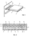
- FIG. 1 of the drawings there is shown the general construction of an IC cooling structure which applies to all the preferred embodiments to be described.
- a printed circuit board 1 is loaded with a plurality of ICs.
- Support members 7 are affixed to the upper surface of the circuit board 1, while a cold plate 5 is securely mounted on the support members 7.
- Connectors 10 and 9 are affixed to the circuit board 1 and a mother board 8, respectively. When the connector 10 is inserted into the connector 9, the circuit board 1 is electrically connected to the mother board 8.
- FIG. 1 is merely representative of major characteristics included in the structure of the present invention and will be modified in various ways to suit an application.
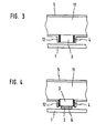
- a first embodiment of the present invention comprises a printed circuit board 1, ICs 2, heat conductors 3, silicone gel 4, the cold plate 5, a compound 6, the support members 7, a coolant passageway 11, nozzles 14, O-rings 21, hollow cylindrical members 22, a coolant inlet 23, and a coolant outlet 24.
- the cylindrical members 22 are affixed to the cold plate 5.
- the O-rings 21 are each received in a groove formed in a portion where the associated cylindrical member 22 and the cold plate 15 join each other.
- the O-ring 21 prevents a coolant from leaking from the interior of the cylindrical member 22.
- the cylindrical members 22 are associated one-to-one with the ICs 2 and positioned just above the ICs.
- the heat conductors 3 are each received in respective cylindrical member 22 and formed into a hollow cylindrical configuration closed at one end thereof.
- the heat conductors 3 have a greater diameter than the cylindrical members 22.
- the closed end of each heat conductor 3 is flat.
- the heat conductors 3 are made of a material having high thermal conductivity, high resistivity to water, and high adhesion to the silicone gel 4. Copper is one of the materials satisfying such three conditions.
- the heat conductors 3 are provided with strength great enough to withstand the pressure of a coolant and erosion. This degree of strength can be implemented if the thickness of the heat conductors 3 is increased.
- the heat conductors 3 are received in the associated cylindrical members 22 such that their closed ends face the ICs 2.
- the silicone gel 4 fills the gaps between the cylindrical members 22 and the associated heat conductors 3, thereby bonding them to each other.
- Each cylindrical member 22 and respective heat conductor 3 form a cup-like receptacle.
- the silicone gel 4 has elasticity and allows the heat conductors 3 to move in the up-and-down direction and to incline. Such a movement of the heat conductors 3 is caused by an external force. When the extraneous force is removed, the heat conductors 3 return to their original position due to the elasticity of the silicone gel 4.
- the range over which the heat conductors 3 are movable depends on the material and thickness of the silicone gel 4.
- silicone gel 4 is selected as a member for bonding the cylindrical members 22 and heat conductors 3 is that it is chemically stable and desirably elastic. Such properties of the silicone gel 4 are achievable not only in air but also in water.
- the silicone gel 4 applicable to the illustrative embodiment should preferably satisfy three different conditions, i.e., high resistivity to shear stresses, a broad range of usable temperatures, and resistivity to water.
- the silicone gel 4 should be usable at temperatures of -50°C to 200°C.
- the cold plate 5 has the inlet 23, outlet 24 and passageway 11 for a coolant.
- the passageway 11 is communicated to nozzles 14 each of which extends into respective heat conductor 3.
- a flat member 5-1 is formed with grooves which constitute the horizontal portions of the passageway 11.
- a flat member 5-2 is formed with through holes to constitute the vertical portions of the passageway 11. Finally, the flat portions 5-1 and 5-2 are joined with each other.
- the ICs 2 mounted on the circuit board 1 are positioned such that their heat radiating surfaces face upward.
- the compound 6 is adhered to each IC 2 and implemented by a flexible substance which is the mixture of silicone oil or similar base material and a filler.
- the filler comprises an electrically insulating and thermally conductive material, e.g., metal oxide or boron nitride.
- the filler provides the compound 6 with high thermal conductivity. Specifically, from the heat conduction and economy standpoint, it is preferable to use an epoxy resin as the base material and to mix silver therewith as the filler.
- the support members 7 are affixed to the upper surface of the circuit board 1.
- the cold plate 5 carrying the cylindrical members 22 and heat conductors 3 thereon is affixed to the support members 7.
- the flat portions of the heat conductors 3 are pressed against the associated ICs 2, while the heat conductors 3 are each moved in matching relation to the height and inclination of the underlying IC 2.
- the upper surfaces of the ICs 2 and the flat portions of the associated heat conductors 3 are brought into close contact with each other.
- the compound 6 intervening between the ICs 2 and the heat conductors 3 is squeezed flat, thereby filling up the gaps between the upper surfaces of the ICs and the heat conductors 3. This further enhances the close contact of the ICs 2 and heat conductors 3.
- the deformation of the silicone gel 4 and that of the compound 6 eliminate the factors obstructing contact as stated previously.
- a coolant is introduced into the passageway 11 via the inlet 23.
- the coolant jets from the nozzle 14 of the passageway 11 toward the flat portion of the heat conductor 3 in which the nozzle 14 is disposed, and then strikes against the flat portion.
- Heat generated by the IC 2 is absorbed by the coolant filling the heat conductor 3 via the flat portion of the heat conductor.
- the coolant flows into the following portion of the passageway 11 and then jets into the next heat conductor 3 via the associated nozzle 14.
- the coolant that has flown through all the heat conductors 3 is discharged from the outlet 24.
- the heat conductors 3 can be pulled out of the associated cylindrical members 22. Also, by pulling out the heat conductors 3, it is possible to remove impurities deposited therein. After the repair, the heat conductors 3 are again inserted into the cylindrical members 22, and then the silicone gel 4 is injected into the gaps between the heat conductors 3 and the cylindrical members 22.
- the embodiment described above has the following advantages. Since the heat conductors 3 are each implemented as a single member, they exhibit high thermal conductivity. Since the flat portions of the heat conductors 3 contact the associated ICs 2, the heat conductors 3 and ICs 2 contact each other over a broad area. In addition, the heat conductors 3 are strong enough to allow a minimum of damage thereto to occur.
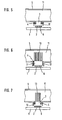
- a second embodiment of the present invention comprises the heat conductor 3, silicone gel 4, cold plate 5, and passageway 11.
- the members constituting the embodiment are made of the same materials as the members of the first embodiment.
- the cold plate 5 is formed with a circular hole through the lower portion thereof, and a flange 12 surrounding the hole.
- the heat conductor 3 is formed into a cylindrical configuration and inserted in the hole of the cold plate 5.
- the silicone gel 4 fills the gap between the flange 12 and the heat conductor 3, thereby bonding them together.
- the heat conductor 3 is movable due to the elasticity of the silicone gel 4.
- the cold plate 5 is affixed to the printed circuit board 1.
- the heat conductor 3 is pressed against the IC 2 mounted on the circuit board 1, while moving in matching relation to the height and inclination of the IC 2.
- the upper surface of the IC 2 and the flat portion of the heat conductor 3 are brought into close contact with each other.
- the compound 6 intervening between the IC 2 and the heat conductor 3 is squeezed flat, filling up the gap between the top of the IC 2 and the flat portion of the heat conductor 3. This further enhances the close contact of the IC 2 and heat conductor 3.
- the silicone gel 4 and compound 6, therefore, eliminate the factors obstructing contact due to their deformation.
- a third embodiment of the present invention comprises the printed circuit board 1, IC 2, heat conductor 3, silicone gel 4, cold plate 5 and compound 6.
- the cold plate 5 is formed with a hole, as in the second embodiment.
- the heat conductor 3 is received in the hole of the cold plate 5 and implemented as a cylinder having a flange 12.
- the silicone gel 4 is injected into the gap between the flange 12 and the cold plate 5 so as to bond the heat conductor 3 and cold plate 5.
- the heat conductor 3 is movable due to the elasticity of the silicone gel 4.
- the deformation of the silicone gel 4 is derived mainly from a shear stress.
- the silicone gel 4 deforms mainly on the basis of a normal stress. This is successful in achieving higher reliability regarding the bonding surfaces of the silicone gel 4.
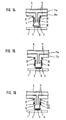
- a fourth embodiment of the present invention is essentially similar to the second embodiment, FIG. 4, except for the configuration of the heat conductor 3. As shown, fins 13 extend out from the top of the heat conductor 3. The heat conductor 3 is positioned such that the fins 13 extend in the same direction as the flow of the coolant so as not to obstruct the coolant.
- fifth embodiment of the present invention is essentially similar to the third embodiment, FIG. 5, except for the configuration of the heat conductor 3. As shown, fins 13 extend out from the top of the heat conductor 3. The heat conductor 3 is positioned such that the fins 13 extend in the same direction as the flow of the coolant so as not to obstruct the coolant.
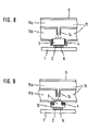
- a sixth embodiment of the present invention is essentially similar to the second embodiment, FIG. 4, except for the configuration of the passageway 11.
- the passageway 11 is divided into a first and a second passageway 11-a and 11-b by a wall.
- the wall partitioning the passageways 11-a and 11-b is formed with a hole in which the nozzle 14 is fitted.
- the coolant flowing through the passageway 11 jets toward the heat conductor 3 via the nozzle 14. When striking against the heat conductor 3, the coolant absorbs the heat of the heat conductor 3 efficiently.
- This embodiment achieves higher cooling efficiency than the second embodiment since it causes the coolant to cool the heat conductor 3 by striking against the heat conductor 3.
- a seventh embodiment of the present invention is shown in FIG. 9 and essentially similar to the third embodiment, FIG. 5, except for the configuration of the passageway 11.
- the passageway 11 is divided into a first and a second passageway 11-a and 11-b by a wall.
- the wall partitioning the passageways 11-a and 11-b is formed with a hole in which the nozzle 14 is fitted.
- the coolant flowing through the passageway 11 jets toward the heat conductor 3 via the nozzle 14. When striking against the heast conductor 3, the coolant absorbs the heat of the heat conductor 3 efficiently.
- This embodiment achieves higher cooling efficiency than the third embodiment since it causes the coolant to cool the heat conductor 3 by striking against the heat conductor 3.
- FIG. 10 shows an eighth embodiment of the present invention.
- the heat conductor 3 is provided on both of the upper and lower surfaces of the cold plate 5.
- the cold plate 5 is formed with a hole in each of the upper and lower walls thereof.
- a printed circuit board 1a, an IC 2a, a heat conductor 3a, silicone gel 4a, a compound 6a and a flange 12a are positioned on the lower portion of the cold plate 5 and respectively correspond to the circuit board 1, IC 2, heat conductor 3, gel 4, compound 6, and flange 12 of the second embodiment.
- the constituent parts 1a, 2a, 3a, 4a, 6a and 12a are assembled in the same manner as in the second embodiment.
- a printed circuit board 1b, an IC 2b, a heat conductor 3b, silicone gel 4b, a compound 6b and a flange 12b are provided on the upper portion of the cold plate 5 and respectively correspond to the constituents 1, 2, 3, 4, 6 and 12 of the second embodiment.
- the component parts 1b, 2b, 3b, 4b, 6b and 12b are also assembled in the same manner as in the second embodiment.
- This embodiment is capable of cooling ICs at opposite surfaces of a single cold plate 5 and, therefore, enhances the packaging density of the circuit board 1.
- the major characteristic of the present embodiment is that a cooling structure is provided on both surfaces of the cold plate 5. It follows that any one of the structures of the embodiments may be provided on both surfaces of the cold plate 5 in place of the structure of the second embodiment. Moreover, the structures on the upper and lower surfaces of the cold plate 5 may even be different from each other.
- FIG. 11 This embodiment is essentially similar to the sixth embodiment, FIG. 8, except for the configuration of the heat conductor 3.
- the heat conductor 3 is formed with a recess 20 and inserted in the flange 12 such that the recess 20 faces the nozzle 14.
- the recess 20 reduces the distance between the IC 2 and the coolant, compared to the sixth embodiment.
- the coolant jetted from the nozzle 14 strikes against the bottom of the recess 20 and absorbs the heat of the heat conductor 3.
- the distance between the IC 2 and the coolant is shorter than in the sixth embodiment due to the recess 20, as stated above. Hence, this embodiment achieves further higher cooling efficiency than the sixth embodiment.
- a tenth embodiment of the present invention is essentially similar to the first embodiment except for the configuration of the passageway 11.
- the passageway 11 is divided into a first and a second passageway 11-a and 11-b, respectively.
- a hole is formed through the lower portion of the cold plate 5, while a hollow cylindrical member 22 is fitted in the hole.
- a hole is also formed through the wall partitioning the two passageways 11-a and 11-b.
- the nozzle 14 is fitted in the hole of this wall and extends through the hole of the cold plate 5 into the hollow cylindrical member 22.
- the coolant fed under pressure to the passageway 11 jets toward the heat conductor 3 via the nozzle 14. When striking against the heat conductor 3, the coolant absorbs the heat of the heat conductor 3 efficiently. The coolant absorbed the heat is discharged through the passageway 11-b.
- the coolant absorbed the heat of one heat conductor 3 is not fed to another heat conductor 3. This further enhances the cooling efficiency adhievable with the first embodiment. Further, since the coolant of the same temperature is fed to all the heat conductors 3, the ICs 2 can be cooled evenly.
- an eleventh embodiment of the present invention is essentially similar to the tenth embodiment except for the configuration of the heat conductor 3.
- the heat conductor 3 has a greater diameter than the hollow cylindrical member 22.
- the cylindrical member 22 is received in the heat conductor 3.
- the silicone gel 4 is injected into the gap between the heat conductor 3 and the cylindrical member 22.
- a twelfth embodiment of the present invention is essentially similar to the tenth embodiment except for the configuration of the heat conductor 3.
- the lower end portion of the heat conductor 3 is greater in diameter than the other portion.
- the lower end of the heat conductor 3 is broad enough to sufficiently cover the IC 2.
- the entire surface of the IC 2 can be cooled even when the cylindrical member 22 has a relatively small diameter. Since the cylindrical member 22 can be provided with a small diameter, it is possible to arrange a greater number of cylindrical members 22 in a given area than in the tenth embodiment. Therefore, this embodiment is particularly feasible for the high density packaging of ICs.
- a thirteenth embodiment of the present invention is essentially similar to the tenth embodiment except for the configurations of the hollow cylindrical member 22 and heat conductor 3.
- the cylindrical member 22 is flared from the upper end to the lower end, i.e., the diameter sequentially increases as the distance from the cold plate 5 increases.
- the heat conductor 3 is also flared from the upper end to the lower end. Since both the cylindrical member 22 and the heat conductor 3 are flared, the flat portion of the heat conductor 3 has an area great enough to cover the IC 2 despite that the diameter of the member 22 adjoining the cold plate 5 is small.
- This embodiment is advantageously applicable to the high density packaging of ICs 2.
- the present embodiment is characterized in that the cylindrical member 22 and heat conductor 3 are each provided with a flared configuration. It follows that such a configuration of the members 22 and 3 is also applicable to the eleventh embodiment, FIG. 13.
- FIG. 16 shows a fourteenth embodiment of the present invention which is essentially similar to the tenth embodiment except for the configurations of the hollow cylindrical member 22 and heat conductor 3.
- the cylindrical member 22 has a flange 12b at the upper end thereof.
- the heat conductor 3 has a flange 12a at the upper end thereof.
- the silicone gel 4 fills up the gap between the flanges 12a and 12b, thereby bonding the cylindrical member 22 and heat conductor 3.
- the deformation of the silicone gel 4 is derived mainly from a normal stress, as in the third embodiment. This is successful in achieving bond as reliable as in the third embodiment.
- a heat conductor is implemented by a single member and, therefore, has high heat conductivity. Further, since the heat conductor has a flat portion contacting an IC, the heat conductor and IC contact each other over a broad area. In addition, the heat conductor 3 is sufficiently strong and has a minimum chance of damage.
- the invention may be embodied in other specific forms.
- the heat conductor 3 may be provided with a rectangular shape, whether it be hollow or not, in place of a cylindrical shape shown and described. Further, the major characteristic features of the various embodiments may be combined in a desired manner.
- the present embodiment are therefore to be considered in all respects as illustrative and not restrictive, the scope of the invention being indicated by the appended claims rather than by the foregoing description and all changes which come within the meaning and range of equivalency of the claims are therefore intended to be embraced therein.
Landscapes
- Cooling Or The Like Of Semiconductors Or Solid State Devices (AREA)
Description
Claims (15)
- A structure for cooling an integrated circuit (IC) comprising:CHARACTERIZED IN THATa printed circuit board (1);an IC (2) mounted on said printed circuit board (1);a heat conductor (3) contacting said IC(2) anda cold plate (5) formed with a passageway (11) for a cooling fluid which cools said heat conductor (3);said heat conductor (3) is elastically held by said cold plate (5) via a silicone gel (4).
- A structure as claimed in claim 1,
CHARACTERIZED IN THATa hollow cylindrical member (22) is mounted on said cold plate (5);that said heat conductor (3) comprises a hollow cylindrical portion and a flat portion closing one end of said hollow cylindrical portion;that said hollow cylindrical portion is arranged inside said hollow cylindrical member (22) while said flat portion contacting said IC (2);and that said silicone gel (4) fills a gap between said hollow cylindrical member (22) and said heat conductor (3). - A structure as claimed in claim 1,
CHARACTERIZED IN THAT
a hole is formed in said cold plate (5) and communicates to said passageway (11), and that said heat conductor (3) is received in said hole. - A structure as claimed in claim 3,
CHARACTERIZED IN THAT
a flange (12) surrounds said hole, and that said silicone gel (4) fills a gap between said flange (12) and said heat conductor (3). - A structure as claimed in claim 3,
CHARACTERIZED IN THAT
a flange (12) surrounds said heat conductor (3), and that said silicone gel (4) fills a gap between said flange (12) and said cold plate (5). - A structure as claimed in claim 4 and 5,
CHARACTERIZED IN THAT
said heat conductor (3) is provided with fins (13). - A structure as claimed in claim 4 and 5
CHARACTERIZED IN THAT
said passageway (11) comprises a first passageway (11b) in which said hole is formed, and a second passageway (11a) in which a nozzle (14) is fitted for jetting the cooling fluid toward said heat conductor (3) - A structure as claimed in claim 3,
CHARACTERIZED IN THAT
said heat conductor (3) comprises a recess (20) facing said passageway (11). - A structure as claimed in claim 1,
CHARACTERIZED IN THAT
said passageway (11) comprises a first passageway (11a) and a second passageway (11b);that a hole is formed in said cold plate (5) and communicated to said second passageway (11b);that a hollow cylindrical member (22) is fitted in said hole;that said heat conductor (3) comprises a hollow cylindrical portion and a flat portion closing one end of said hollow cylindrical portion;that said hollow cylindrical portion is arranged inside said hollow cylindrical member (22) while said flat portion contacting said IC (2);that said silicone gel (4) fills a gap between said hollow cylindrical member (22) and said heat conductor (3) ;and that a nozzle (14) jets the cooling fluid flowing through said first passageway (11a) into said heat conductor (3). - A structure as claimed in claim 1,
CHARACTERIZED IN THAT
said passageway (11) comprises a first passageway (11a) and a second passageway (11b);that a hole is formed in said cold plate (5) and communicated to said second passageway (11b);that a hollow cylindrical member (22) is fitted in said hole;said heat conductor (3) comprises a hollow cylindrical portion and a flat portion closing one end of said hollow cylindrical portion;that said hollow cylindrical member (22) is arranged inside said hollow cylindrical portion while said flat portion contacting said IC (2);that said silicone gel (4) fills a gap between said hollow cylindrical member (22) and said heat conductor (3);and that a nozzle (14) jets the cooling fluid flowing through said first passageway (11a) into said heat conductor (3). - A structure as claimed in any one of claims 2, 8 and 9.
CHARACTERIZED IN THAT
said heat conductor (3) has a greater diameter at a closed end portion thereof than at the other portion. - A structure as claimed in any one of claims 2, 8 and 9.
CHARACTERIZED IN THAT
said heat conductor (3) has a diameter sequentially increasing as a distance from said cold plate (5) increases, and that said hollow cylindrical member (22) having a diameter sequentially increasing as said distance from said cold plate (5) increases. - A structure as claimed in claim 1,
CHARACTERIZED IN THAT
said cold plate (5) is formed with a hole communicating to said passageway (11);that a hollow cylindrical member (22) fitted in said hole and provided with a first flange (12a) around one end thereof;that said heat conductor comprising a hollow cylindrical portion, a flat portion closing one end of said hollow cylindrical portion, and a second flange (12b) surrounding said one end of said hollow cylindrical portion, said flat portion contacting said IC (2);and that a nozzle (14) jets the cooling fluid flowing through said first passageway (11) into said heat conductor (3) - A structure as claimed in any one of claims 1-10,
CHARACTERIZED IN THAT
a compoung (6) is interposed between said heat conductor (3) and said IC (2). - A structure for cooling an integrated circuit (IC) comprisingcharacterized in thata first printed circuit board (1a),a first IC (2a) mounted on said first printed circuit board (1a), a second printed circuit board (1b), which is arranged opposite to said first board (1a),a second IC (2b) mounted opposite to said first IC (2a) on said second printed circuit board (1b),a first heat conductor (3a) contacting said first IC (2a),a second heat conductor (3b) contacting said second IC (2b),a cold plate (5) formed with a passageway (11) for a cooling fluid, which cools said first and second conductor (3a) and (3b) is arranged in the centre between said first printed circuit board (1a) and said second printed circuit board (1b), and said first and second heat conductors (3a) and (3b) are held elastically by said cold plate (5) via a silicone gel (4).
Applications Claiming Priority (2)
| Application Number | Priority Date | Filing Date | Title |
|---|---|---|---|
| JP29752092 | 1992-11-09 | ||
| JP297520/92 | 1992-11-09 |
Publications (3)
| Publication Number | Publication Date |
|---|---|
| EP0597425A2 EP0597425A2 (en) | 1994-05-18 |
| EP0597425A3 EP0597425A3 (en) | 1995-03-22 |
| EP0597425B1 true EP0597425B1 (en) | 1998-09-16 |
Family
ID=17847591
Family Applications (1)
| Application Number | Title | Priority Date | Filing Date |
|---|---|---|---|
| EP93118087A Expired - Lifetime EP0597425B1 (en) | 1992-11-09 | 1993-11-08 | Structure for cooling an integrated circuit |
Country Status (4)
| Country | Link |
|---|---|
| US (1) | US5420753A (en) |
| EP (1) | EP0597425B1 (en) |
| CA (1) | CA2102662C (en) |
| DE (1) | DE69321070T2 (en) |
Families Citing this family (24)
| Publication number | Priority date | Publication date | Assignee | Title |
|---|---|---|---|---|
| DE19608677B4 (en) * | 1996-03-06 | 2008-02-07 | Vorwerk & Co. Interholding Gmbh | Cooling arrangement for arranged on a printed circuit board electronic components |
| JPH1041386A (en) * | 1996-07-24 | 1998-02-13 | Mitsubishi Electric Corp | Method for manufacturing semiconductor device |
| DE69827304T2 (en) * | 1998-12-30 | 2005-11-03 | Acqiris Sa | ELECTRONIC MODULE WITH COOLING ELEMENTS FOR ELECTRONIC COMPONENTS |
| US7385821B1 (en) * | 2001-12-06 | 2008-06-10 | Apple Inc. | Cooling method for ICS |
| US6778393B2 (en) * | 2002-12-02 | 2004-08-17 | International Business Machines Corporation | Cooling device with multiple compliant elements |
| US7084495B2 (en) * | 2003-10-16 | 2006-08-01 | Intel Corporation | Electroosmotic pumps using porous frits for cooling integrated circuit stacks |
| US6992382B2 (en) * | 2003-12-29 | 2006-01-31 | Intel Corporation | Integrated micro channels and manifold/plenum using separate silicon or low-cost polycrystalline silicon |
| WO2006029527A1 (en) * | 2004-09-13 | 2006-03-23 | Lighthaus Logic Inc. | Structures for holding cards incorporating electronic and/or micromachined components |
| US7418998B2 (en) * | 2005-06-30 | 2008-09-02 | Intel Corporation | Chamber sealing valve |
| US7515418B2 (en) * | 2005-09-26 | 2009-04-07 | Curtiss-Wright Controls, Inc. | Adjustable height liquid cooler in liquid flow through plate |
| US7324336B2 (en) * | 2005-09-27 | 2008-01-29 | Lockheed Martin Corporation | Flow through cooling assemblies for conduction-cooled circuit modules |
| US7298617B2 (en) * | 2005-10-25 | 2007-11-20 | International Business Machines Corporation | Cooling apparatus and method employing discrete cold plates disposed between a module enclosure and electronics components to be cooled |
| US7298618B2 (en) * | 2005-10-25 | 2007-11-20 | International Business Machines Corporation | Cooling apparatuses and methods employing discrete cold plates compliantly coupled between a common manifold and electronics components of an assembly to be cooled |
| DE102006008973B4 (en) * | 2006-02-23 | 2014-09-11 | Von Ardenne Anlagentechnik Gmbh | Coolable carrier plate for targets in vacuum atomizing systems |
| CN101505861B (en) * | 2007-09-14 | 2013-09-11 | 株式会社爱德万测试 | Advanced thermal control interface |
| US8302671B2 (en) * | 2008-04-29 | 2012-11-06 | Raytheon Company | Scaleable parallel flow micro-channel heat exchanger and method for manufacturing same |
| US8358505B2 (en) * | 2010-10-28 | 2013-01-22 | Asetek A/S | Integrated liquid cooling system |
| US8432691B2 (en) | 2010-10-28 | 2013-04-30 | Asetek A/S | Liquid cooling system for an electronic system |
| EP2633377A1 (en) * | 2010-10-28 | 2013-09-04 | Asetek A/S | Integrated liquid cooling system |
| EP2842678B1 (en) * | 2013-08-29 | 2017-12-06 | Agie Charmilles SA | Wire Electric Discharge Machine |
| US9721870B2 (en) * | 2014-12-05 | 2017-08-01 | International Business Machines Corporation | Cooling structure for electronic boards |
| DE102020203884A1 (en) * | 2020-03-25 | 2021-09-30 | Zf Friedrichshafen Ag | Cooling system |
| WO2022192031A1 (en) * | 2021-03-08 | 2022-09-15 | Tesla, Inc. | Cold plate with integrated sliding pedestal and processing system including the same |
| DE102022126106B4 (en) | 2022-10-10 | 2026-01-22 | Erwin Quarder Systemtechnik Gmbh | Cooling device |
Family Cites Families (14)
| Publication number | Priority date | Publication date | Assignee | Title |
|---|---|---|---|---|
| US4193445A (en) * | 1978-06-29 | 1980-03-18 | International Business Machines Corporation | Conduction cooled module |
| CA1227886A (en) * | 1984-01-26 | 1987-10-06 | Haruhiko Yamamoto | Liquid-cooling module system for electronic circuit components |
| US4649990A (en) * | 1985-05-06 | 1987-03-17 | Hitachi, Ltd. | Heat-conducting cooling module |
| US4748495A (en) * | 1985-08-08 | 1988-05-31 | Dypax Systems Corporation | High density multi-chip interconnection and cooling package |
| US4879632A (en) * | 1985-10-04 | 1989-11-07 | Fujitsu Limited | Cooling system for an electronic circuit device |
| JPS62136865A (en) * | 1985-12-11 | 1987-06-19 | Hitachi Ltd | Module mounting structure |
| FR2592988B1 (en) * | 1986-01-16 | 1988-03-18 | Jeumont Schneider | SEMICONDUCTOR COOLING DEVICES |
| JPS63313843A (en) * | 1987-06-16 | 1988-12-21 | Hitachi Cable Ltd | Heat transfer structure for cooling for heating element |
| JPH088328B2 (en) * | 1987-06-30 | 1996-01-29 | 富士通株式会社 | Heat sink assembly for electronic equipment |
| US5023695A (en) * | 1988-05-09 | 1991-06-11 | Nec Corporation | Flat cooling structure of integrated circuit |
| US4882654A (en) * | 1988-12-22 | 1989-11-21 | Microelectronics And Computer Technology Corporation | Method and apparatus for adjustably mounting a heat exchanger for an electronic component |
| US5227663A (en) * | 1989-12-19 | 1993-07-13 | Lsi Logic Corporation | Integral dam and heat sink for semiconductor device assembly |
| GB2249869B (en) * | 1990-09-17 | 1994-10-12 | Fuji Electric Co Ltd | Semiconductor device |
| US5213868A (en) * | 1991-08-13 | 1993-05-25 | Chomerics, Inc. | Thermally conductive interface materials and methods of using the same |
-
1993
- 1993-11-08 CA CA002102662A patent/CA2102662C/en not_active Expired - Fee Related
- 1993-11-08 DE DE69321070T patent/DE69321070T2/en not_active Expired - Fee Related
- 1993-11-08 EP EP93118087A patent/EP0597425B1/en not_active Expired - Lifetime
- 1993-11-09 US US08/149,558 patent/US5420753A/en not_active Expired - Fee Related
Also Published As
| Publication number | Publication date |
|---|---|
| CA2102662C (en) | 1997-10-07 |
| DE69321070D1 (en) | 1998-10-22 |
| EP0597425A2 (en) | 1994-05-18 |
| CA2102662A1 (en) | 1994-05-10 |
| US5420753A (en) | 1995-05-30 |
| EP0597425A3 (en) | 1995-03-22 |
| DE69321070T2 (en) | 1999-06-10 |
Similar Documents
| Publication | Publication Date | Title |
|---|---|---|
| US5420753A (en) | Structure for cooling an integrated circuit | |
| US6154369A (en) | Electronic assembly for removing heat from a semiconductor device | |
| US6504243B1 (en) | Removable heat transfer apparatus for a pin grid array (PGA) device, and associated installation and removal methods | |
| US4338621A (en) | Hermetic integrated circuit package for high density high power applications | |
| US6462410B1 (en) | Integrated circuit component temperature gradient reducer | |
| US5006924A (en) | Heat sink for utilization with high density integrated circuit substrates | |
| US6862186B2 (en) | Stack up assembly | |
| US7808781B2 (en) | Apparatus and methods for high-performance liquid cooling of multiple chips with disparate cooling requirements | |
| US5028989A (en) | Semiconductor cooling module | |
| US5052481A (en) | High conduction cooling module having internal fins and compliant interfaces for vlsi chip technology | |
| EP0602298B1 (en) | Support for a semiconductor package | |
| Goldberg | Narrow channel forced air heat sink | |
| US6037658A (en) | Electronic package with heat transfer means | |
| US7739876B2 (en) | Socket enabled current delivery to a thermoelectric cooler to cool an in-substrate voltage regulator | |
| US5926369A (en) | Vertically integrated multi-chip circuit package with heat-sink support | |
| US5045922A (en) | Installation structure of integrated circuit devices | |
| JPH0315341B2 (en) | ||
| EP0717440A2 (en) | Cooling device of multi-chip module | |
| JPS6094749A (en) | Ic-chip cooling device | |
| JPH0656867B2 (en) | Integrated circuit chip cooler | |
| US20060060952A1 (en) | Heat spreader for non-uniform power dissipation | |
| US7385821B1 (en) | Cooling method for ICS | |
| US5050036A (en) | Liquid cooled integrated circuit assembly | |
| EP0054069A1 (en) | Heat pin integrated circuit packaging | |
| JPH05304234A (en) | Cooling structure for integrated circuit |
Legal Events
| Date | Code | Title | Description |
|---|---|---|---|
| PUAI | Public reference made under article 153(3) epc to a published international application that has entered the european phase |
Free format text: ORIGINAL CODE: 0009012 |
|
| AK | Designated contracting states |
Kind code of ref document: A2 Designated state(s): DE FR GB NL |
|
| PUAL | Search report despatched |
Free format text: ORIGINAL CODE: 0009013 |
|
| AK | Designated contracting states |
Kind code of ref document: A3 Designated state(s): DE FR GB NL |
|
| 17P | Request for examination filed |
Effective date: 19950215 |
|
| 17Q | First examination report despatched |
Effective date: 19950925 |
|
| GRAG | Despatch of communication of intention to grant |
Free format text: ORIGINAL CODE: EPIDOS AGRA |
|
| GRAG | Despatch of communication of intention to grant |
Free format text: ORIGINAL CODE: EPIDOS AGRA |
|
| GRAH | Despatch of communication of intention to grant a patent |
Free format text: ORIGINAL CODE: EPIDOS IGRA |
|
| GRAH | Despatch of communication of intention to grant a patent |
Free format text: ORIGINAL CODE: EPIDOS IGRA |
|
| GRAA | (expected) grant |
Free format text: ORIGINAL CODE: 0009210 |
|
| AK | Designated contracting states |
Kind code of ref document: B1 Designated state(s): DE FR GB NL |
|
| REF | Corresponds to: |
Ref document number: 69321070 Country of ref document: DE Date of ref document: 19981022 |
|
| PGFP | Annual fee paid to national office [announced via postgrant information from national office to epo] |
Ref country code: GB Payment date: 19981113 Year of fee payment: 6 |
|
| PGFP | Annual fee paid to national office [announced via postgrant information from national office to epo] |
Ref country code: FR Payment date: 19981127 Year of fee payment: 6 |
|
| PGFP | Annual fee paid to national office [announced via postgrant information from national office to epo] |
Ref country code: NL Payment date: 19981130 Year of fee payment: 6 |
|
| ET | Fr: translation filed | ||
| PGFP | Annual fee paid to national office [announced via postgrant information from national office to epo] |
Ref country code: DE Payment date: 19990131 Year of fee payment: 6 |
|
| PLBE | No opposition filed within time limit |
Free format text: ORIGINAL CODE: 0009261 |
|
| STAA | Information on the status of an ep patent application or granted ep patent |
Free format text: STATUS: NO OPPOSITION FILED WITHIN TIME LIMIT |
|
| RAP2 | Party data changed (patent owner data changed or rights of a patent transferred) |
Owner name: NEC CORPORATION |
|
| 26N | No opposition filed | ||
| NLXE | Nl: other communications concerning ep-patents (part 3 heading xe) |
Free format text: PAT. BUL. 12/98 PAGE 1717: CORR.: NEC CORPORATION. |
|
| REG | Reference to a national code |
Ref country code: FR Ref legal event code: RM |
|
| PG25 | Lapsed in a contracting state [announced via postgrant information from national office to epo] |
Ref country code: GB Free format text: LAPSE BECAUSE OF NON-PAYMENT OF DUE FEES Effective date: 19991108 |
|
| PG25 | Lapsed in a contracting state [announced via postgrant information from national office to epo] |
Ref country code: NL Free format text: LAPSE BECAUSE OF NON-PAYMENT OF DUE FEES Effective date: 20000601 |
|
| GBPC | Gb: european patent ceased through non-payment of renewal fee |
Effective date: 19991108 |
|
| PG25 | Lapsed in a contracting state [announced via postgrant information from national office to epo] |
Ref country code: FR Free format text: LAPSE BECAUSE OF NON-PAYMENT OF DUE FEES Effective date: 20000731 |
|
| NLV4 | Nl: lapsed or anulled due to non-payment of the annual fee |
Effective date: 20000601 |
|
| PG25 | Lapsed in a contracting state [announced via postgrant information from national office to epo] |
Ref country code: DE Free format text: LAPSE BECAUSE OF NON-PAYMENT OF DUE FEES Effective date: 20000901 |
|
| REG | Reference to a national code |
Ref country code: FR Ref legal event code: ST |