EP0596922B1 - Improved turbine and air hose storage housing for portable spray paint guns - Google Patents
Improved turbine and air hose storage housing for portable spray paint guns Download PDFInfo
- Publication number
- EP0596922B1 EP0596922B1 EP92915424A EP92915424A EP0596922B1 EP 0596922 B1 EP0596922 B1 EP 0596922B1 EP 92915424 A EP92915424 A EP 92915424A EP 92915424 A EP92915424 A EP 92915424A EP 0596922 B1 EP0596922 B1 EP 0596922B1
- Authority
- EP
- European Patent Office
- Prior art keywords
- air
- fitting
- cover
- disposed
- fan motor
- Prior art date
- Legal status (The legal status is an assumption and is not a legal conclusion. Google has not performed a legal analysis and makes no representation as to the accuracy of the status listed.)
- Expired - Lifetime
Links
- 239000007921 spray Substances 0.000 title abstract description 3
- 239000003973 paint Substances 0.000 title abstract 2
- 238000010422 painting Methods 0.000 claims description 5
- 238000013022 venting Methods 0.000 claims description 3
- 238000003780 insertion Methods 0.000 description 3
- 230000037431 insertion Effects 0.000 description 3
- 230000000903 blocking effect Effects 0.000 description 2
- 238000007373 indentation Methods 0.000 description 2
- 239000000463 material Substances 0.000 description 2
- 239000012858 resilient material Substances 0.000 description 2
- 229920005830 Polyurethane Foam Polymers 0.000 description 1
- 238000010276 construction Methods 0.000 description 1
- 230000001419 dependent effect Effects 0.000 description 1
- 230000014759 maintenance of location Effects 0.000 description 1
- 229920001296 polysiloxane Polymers 0.000 description 1
- 239000011496 polyurethane foam Substances 0.000 description 1
- 230000000717 retained effect Effects 0.000 description 1
- 238000007789 sealing Methods 0.000 description 1
Images


Classifications
-
- F—MECHANICAL ENGINEERING; LIGHTING; HEATING; WEAPONS; BLASTING
- F04—POSITIVE - DISPLACEMENT MACHINES FOR LIQUIDS; PUMPS FOR LIQUIDS OR ELASTIC FLUIDS
- F04D—NON-POSITIVE-DISPLACEMENT PUMPS
- F04D29/00—Details, component parts, or accessories
- F04D29/60—Mounting; Assembling; Disassembling
- F04D29/601—Mounting; Assembling; Disassembling specially adapted for elastic fluid pumps
-
- B—PERFORMING OPERATIONS; TRANSPORTING
- B05—SPRAYING OR ATOMISING IN GENERAL; APPLYING FLUENT MATERIALS TO SURFACES, IN GENERAL
- B05B—SPRAYING APPARATUS; ATOMISING APPARATUS; NOZZLES
- B05B7/00—Spraying apparatus for discharge of liquids or other fluent materials from two or more sources, e.g. of liquid and air, of powder and gas
- B05B7/24—Spraying apparatus for discharge of liquids or other fluent materials from two or more sources, e.g. of liquid and air, of powder and gas with means, e.g. a container, for supplying liquid or other fluent material to a discharge device
- B05B7/2489—Spraying apparatus for discharge of liquids or other fluent materials from two or more sources, e.g. of liquid and air, of powder and gas with means, e.g. a container, for supplying liquid or other fluent material to a discharge device an atomising fluid, e.g. a gas, being supplied to the discharge device
- B05B7/2491—Spraying apparatus for discharge of liquids or other fluent materials from two or more sources, e.g. of liquid and air, of powder and gas with means, e.g. a container, for supplying liquid or other fluent material to a discharge device an atomising fluid, e.g. a gas, being supplied to the discharge device characterised by the means for producing or supplying the atomising fluid, e.g. air hoses, air pumps, gas containers, compressors, fans, ventilators, their drives
Definitions
- This invention relates to a portable painting apparatus of the type having an air flow path, including a fan motor assembly having an air outlet delivering air generally axially along an axis of the motor as the air exits the fan motor assembly.
- the US-A-2 532 264 describes a vacuum cleaner of the tank type, having an air flow path, a fan motor assembly, having an air outlet and a cover disposed over the air outlet of the fan motor assembly.
- the present invention provides a portable painting apparatus comprising the features of claim 1.
- the cover of the portable painting apparatus provides an air flow path having a minimum number of restrictions such as turns between the fan motor and the air hose to reduce drag of the air flow.
- the portable painting apparatus preferably includes a housing body which is designed to provide a bottom opening compartment for air hose storage.
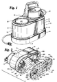
- Figure 1 is a perspective view of the housing.
- Figure 2 is a perspective view of the housing showing the bottom panel removed and hose storage within the housing.
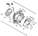
- Figure 2a is a fragmentary exploded view of the top of the bottom panel showing the means for fastening the bottom panel to the housing.
- Figure 3 is an exploded view of the housing shown in Figure 1.
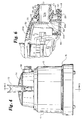
- Figure 4 is an end elevational view of the housing.
- Figure 5 is a sectional view taken along line 5-5 in Figure 4.
- Figure 6 is a fragmentary section through the air exit fitting and upper dome assembly.
- a preferred embodiment of the housing 8 of the present invention is provided with a pair of generally planar vertical sides 10 and 13 and a pair of generally arcuate vertical sides 12 and 14.
- sides 10, 12, 13 and 14 are preferably, but not necessarily, slightly angled from vertical.
- a radius of the arcuate vertical side 12 is preferably, but not necessarily, less than a radius of the arcuate side 14.
- these sides 10-14 define a generally elongate body 15 with an interior space 17 (see Figure 2), the elongate body 15 having an inner perimeter 102.
- the upper surface 16 defines a first slightly tapered cylindrical depression 18 and a second slightly tapered cylindrical depression 20.
- the first depression 18 is divided into an upper and lower tapered sections 122 and 124, a lowest portion 123 of the upper tapered section 122 having a slightly larger radius than a highest portion 125 of the lower tapered section 124.
- a first annular horizontal ledge 126 is located between the upper tapered section 122 and the lower tapered section 124.
- the second depression 20 is divided into an upper and lower tapered cylindrical sections 128 and 130, a lowest portion 129 of the upper tapered section 128 having a slightly larger radius than a highest portion 131 of the lower tapered section 130.
- a circular disc 170 preferably rests on a second annular horizontal ledge 132 between the upper tapered section 128 and the lower tapered section 130 of the second depression 20. The circular disc 170 separates the upper tapered section 128 from the lower tapered section 130.
- a cylindrical surface 118 of the first depression 18 is disposed within the interior space 17.
- a cylindrical surface 120 of the second depression 20 is disposed within interior space 17.
- the upper cylindrical section 128 of second depression 20, as seen in Figure 1, is adapted and designed for removable retention of a spray gun assembly (not shown).
- the first depression 18 is adapted and designed to retain a fan motor 24.
- a filter 26 is preferably disposed within the lower section 124 of the first depression 18 to filter air before the air enters the fan motor 24.
- the filter comprises venting means 308.
- the filter 26 is disposed beneath a bottom vented filter cup 172 having an upper rim 176 which rests on the first horizontal ledge 126.
- a tubular gasket 178 rests between the fan motor 24 and the filter cup upper rim 176.
- the filter cup 172 extends about half way into the lower section 124.
- the lower section 124 of the first depression 18 is vented with a first set of vents 29 to allow entry of air into the depression 18 in response to the vacuum created by the fan motor 24.
- the sides 10-14 are provided with a second set of vents 31 ( Figures 1 and 4) to allow air flow from outside the housing 8 to reach the fan motor 24 through the second set of vents 31 and then through the first set of vents 29 and the filter 26 in response to a vacuum created by operation of the fan motor 24.
- Figures 2 and 4 Polyurethane foam has been found to be a suitable material for filter 26. It is also to be understood that the air inlet for motor 24 is a central opening in its lower or bottom wall.
- annular gasket 28 of a suitable resilient material is located on an upper surface 312 of a motor positioning plate 30 having an outer rim 268 preferably secured to the fan motor 24 such as by screws 31 with another gasket 33 of suitable resilient material located between plate 30 and motor 24 to produce a substantially air-tight seal therebetween.
- the plate 30 surrounds an air outlet 300.
- An inner dome or cover 32 having a circular opening 34 is located over the annular gasket 28 to produce a substantially air-tight seal therebetween.
- An outer dome 36 is located over the inner dome 32. As is also shown in Figure 6, the outer dome 36 defines a threaded bore 38 into which an externally threaded fitting 40 is screwed.
- An interior end 42 of the fitting 40 is adapted and designed to rest within the circular opening 34 of the inner dome 32 with a relatively air-tight seal between fitting 40 and inner dome 32 when the fitting 40 is threaded into the bore 38.
- a smooth surface 136 of a slightly tapered cylindrical section 234 located at the interior end 42 of the fitting 40 which is disposed within the circular opening 34 preferably creates the air-tight seal.
- An exterior end 43 of the fitting 40, which extends out of the threaded bore 38 of the outer dome 36, preferably has an exterior perimeter section 45 with wrench flats thereon.
- the fitting 40 defines a cylindrical passage 47, 310 which communicates between the interior end 42 and the exterior end 43 of the fitting 40.
- the interior end 42 preferably has a grill 49 disposed across the cylindrical passage 49.
- the outer dome 36, inner dome 32, annular gasket 28 and the motor positioning plate 30 are secured to the upper surface 16 surrounding the first depression 18 with screws 44.
- the screws 44 are received in holes 180 in an annular base 46 of the outer dome 36, holes 181 in an annular bottom plate 48 of the inner dome 32, holes 182 in the annular gasket 28, holes 183 in an annular rim 268 of the motor positioning plate 30 and holes 184 in the upper surface 16 around the first depression 18.
- a downwardly extending circumferential lip 50 on the annular base 46 of the outer dome 36 covers the annular bottom plate 48 and the annular gasket 28. This construction causes air flow from the fan motor 24 to be directed into the inner dome 32, through the passage 47 of the fitting 40 with only a single turn of 90° in the air path.
- the inner dome 32 is preferably formed of the annular bottom plate 48, a cylindrical center section 238, an upper section 244 and a horizontally disposed, slightly arched top portion 258.
- the inner dome defines a generally rectangular air plenum 306.
- the cylindrical center section 238 extends upwardly from an inner edge 240 of the annular bottom plate 48.
- An upper end 242 of the cylindrical central section 238 has two horizontal portions 243 extending inwardly therefrom.
- Two vertical arcuate end walls 246 and a pair of elongated side walls 304, 306 extend vertically from the cylindrical central section 238.
- Two panel walls 248 extend upwardly between the arcuate walls 246 from an innermost edge 250 of each of the two horizontal portions 243.
- the panel walls 248 are comprised of a planar lower section 252 having a slight inward incline and an upper section 254 extending upwardly from an upper edge 256 of each planar lower section 252.
- the upper sections 254 preferably have a greater inward incline than the lower sections 252 as may be seen most clearly in Figure 5.
- the arcuate walls 246 and the panel walls 248 are capped by the generally horizontally disposed top portion 258.
- One of the two arcuate walls 246 defines the circular opening 34 generally centered between the panel walls 248.
- the outer dome 36 is preferably formed of an annular base 46, a slightly tapered cylindrical middle portion 262, and a convex ceiling portion 264.
- the cylindrical middle portion 262 of the outer dome 36 extends upwardly from the inner circumference of the annular base 46.
- the ceiling portion 264 is located above and closes the cylindrical middle portion 262.
- the outer dome 36 is preferably provided with an over-arching handle 72 disposed at a right angle to the threaded bore 38.
- the handle 72 has a first handle end 74 disposed near a first end 76 of the elongate body 15 and a second handle end 75 disposed between the first end 76 of the elongate body 15 and a second end 77 of the elongate body 15 near a center 78 of the elongate body 15.
- the outer dome 36 also has an indentation 51 in its upper surface, the indentation 51 having a vertical wall 52 and a horizontal floor 54.
- Figure 5 shows that the horizontal floor 54 has a switch opening 58 defined therein having an on-off switch 56 disposed therein.
- the on-off switch 56 has first and second sets of leads 62, 64 disposed within the outer dome 36.
- the first set of leads 62 also passes through the inner dome 32 through a lead opening 60 (shown in Figure 3) in the inner dome 32 and connects to the fan motor 24.
- the lead opening 60 in the inner dome 32 is preferably sealed after the first set of leads 62 is inserted to make the lead opening 60 air-tight. Silicone caulk 186 has been found to be a suitable material for sealing opening 60.
- the second set of leads 64 connects the on-off switch 56 and an electrical cord 66. Referring to Figure 5, the outer dome 36 defines an electrical cord opening 68 disposed beneath the first handle end 74 of the over-arching handle 72 in which a strain relief connector 70 is received.
- a set of cord connectors "C" connects the second set of leads 64 within the outer dome 36 to the electrical cord 66.
- the housing 8 is preferably provided with a bottom cover 80 having a generally planar section 82 and a first and second cylindrical well sections 84 and 86.
- the generally planar section 82 defines a waffle-like patterned grate of venting holes 266 communicating between a top 88 and bottom 90 of the bottom cover 80.
- the bottom 90 of the bottom cover 80 also has four support feet 92 disposed thereon.
- An outer perimeter 100 of the bottom cover 80 is adapted and designed to fit within the inner perimeter 102 of the elongate body 15 with the first and second cylindrical well sections 84 and 86 disposed upwardly and aligned with the first and second depressions 18 and 20 of the elongate body 15 respectively.
- first circular rotatable top plate 104 Disposed above the first cylindrical well section 84 is a first circular rotatable top plate 104 having a circumference slightly greater than a respective outer circumference of the first cylindrical well section 84.
- the first top plate 104 is provided with two horizontal beveled flanges 108 extending along a diameter of the first top plate 104.
- the first top plate 104 is disposable within a first annular bottom rim 112 of the first depression 18.
- the first annular bottom rim 112 of the first depression 18 defines two diametrically opposed notches 114 adapted and designed to receive the beveled flanges 108.
- the first top plate 104 is rotatable to position the beveled flanges 108 for insertion into radial notches 114 in the first annular bottom rim 112 of the first depression 18. Upon such insertion, the top plate 104 may be rotated up to 90 degrees. Upon rotation of the first top plate 104, the horizontal beveled flanges 108 are no longer aligned with the radial notches 114 and the first top plate 104 is retained within the first depression 18 against the first annular bottom rim 112 by the flanges 108.
- the first cylindrical well section 84 preferably has a first annular backing lip 134 having a smaller inner radius than an inner radius of the first cylindrical well section 84.
- a first cylindrical blocking peg 136 extends upwardly from the first backing lip 134.
- the first top plate 104 defines a first arcuate channel 138 communicating between a front surface 140 and a back surface 142 of the first top plate 104.
- the arc of the first arcuate channel 138 is concentric with the first top plate 104.
- the first blocking peg 136 is disposed within the first arcuate channel 138 and limits axial rotation of the first top plate 104 to a range of 90 degrees.
- a first backing disc 148 is disposed below the first top plate 104.
- the first backing disc 148 has a radius greater than the inner radius of the first annular backing lip 134, and less than the inner radius of the first cylindrical well section 84.
- a lower surface 156 of the first backing disc 148 is provided with a first blade 158 along a diameter of the first backing disc 148.
- An upper surface 157 of the first backing disc 148 has a raised center section 150 concentric with the first backing disc 148.
- the raised center section 150 has a radius slightly less than the inner radius of the first annular backing lip 134.
- Raised center section 150 has a thickness slightly greater than a thickness of a top surface 190 of the first annular backing lip 134 of the first cylindrical well section 84 such that when a top surface 190 of the first backing disc 148 is secured to top plate 104 by a pair of screws 160, 162, the assembly of disc 148 and top plate 104 is free to rotate with respect to lip 134.
- the top surface 190 of the first raised center section 150 is provided with a pair of interlock pegs 152, 154 having a larger radius and a smaller radius respectively, upwardly extending from and symmetrically disposed on the raised center section 150 along a diameter of the raised center section 150.
- the first top plate 104 defines a larger interlock hole 144 and a smaller interlock hole 146 symmetrically disposed along a diameter of the first top plate 104.
- the larger and smaller interlock pegs 152, 154 are positioned for insertion into the larger and smaller interlock holes 144, 146 respectively. Such an interlocking peg and hole arrangement insures correct assembly of the first top plate 104 with the first backing disc 148.
- the first top plate 104 is preferably affixed to the first backing disc 148 with first and second screws 160, 162 received through screw holes 161 in the top plate 104 and secured in screw holes 163 in the first backing disc 148.
- First blade 158 is aligned over a pair of bosses 270 containing screw holes 163 to provide additional strength.
- the second cylindrical well section 86 is removably attachable to the second depression 20 using a second top plate 106 having a second pair of beveled flanges (not shown) inserted into a second pair of radial notches 115 in the same manner in which the first top plate 104 of the cylindrical well section 84 is removably attachable to the first depression 18.
- the inner perimeter 102 of the elongate body 15 is preferably provided with a set of bottom stop ridges 166 to rest against the bottom cover 80 and prevent the bottom cover 80 from deflecting inward into the interior space 17 of body 15.
- An air hose 168 is storable within interior space 17 by wrapping the hose 168 around the cylindrical surfaces 118, 120 of the first and second depressions 18, 20 and then attaching bottom cover 80 to body 15 by inserting both pairs of horizontal beveled flanges 108, (not shown), into their respective pairs of radial notches 114, 116 and rotating the first blade 158 and a second blade 159 to secure the bottom cover 80 in place.
Landscapes
- Engineering & Computer Science (AREA)
- Mechanical Engineering (AREA)
- General Engineering & Computer Science (AREA)
- Nozzles (AREA)
- Electrostatic Spraying Apparatus (AREA)
- Compressor (AREA)
- Structures Of Non-Positive Displacement Pumps (AREA)
- Details Or Accessories Of Spraying Plant Or Apparatus (AREA)
Abstract
Description
- This invention relates to a portable painting apparatus of the type having an air flow path, including a fan motor assembly having an air outlet delivering air generally axially along an axis of the motor as the air exits the fan motor assembly.
- The US-A-2 532 264 describes a vacuum cleaner of the tank type, having an air flow path, a fan motor assembly, having an air outlet and a cover disposed over the air outlet of the fan motor assembly.
- The present invention provides a portable painting apparatus comprising the features of claim 1. The cover of the portable painting apparatus provides an air flow path having a minimum number of restrictions such as turns between the fan motor and the air hose to reduce drag of the air flow. The portable painting apparatus preferably includes a housing body which is designed to provide a bottom opening compartment for air hose storage.
- Further features of this invention are defined in the dependent claims.
- Embodiments of the present invention are described with respect to the enclosed drawings.
- Figure 1 is a perspective view of the housing.
- Figure 2 is a perspective view of the housing showing the bottom panel removed and hose storage within the housing.
- Figure 2a is a fragmentary exploded view of the top of the bottom panel showing the means for fastening the bottom panel to the housing.
- Figure 3 is an exploded view of the housing shown in Figure 1.
- Figure 4 is an end elevational view of the housing.
- Figure 5 is a sectional view taken along line 5-5 in Figure 4; and
- Figure 6 is a fragmentary section through the air exit fitting and upper dome assembly.
- Referring to Figures 1, 2, 3 and 4, a preferred embodiment of the
housing 8 of the present invention is provided with a pair of generally planarvertical sides vertical sides sides vertical side 12 is preferably, but not necessarily, less than a radius of thearcuate side 14. Together with anupper surface 16, these sides 10-14 define a generallyelongate body 15 with an interior space 17 (see Figure 2), theelongate body 15 having aninner perimeter 102. As seen in Figure 5, theupper surface 16 defines a first slightly taperedcylindrical depression 18 and a second slightly taperedcylindrical depression 20. - The
first depression 18 is divided into an upper and lowertapered sections tapered section 122 having a slightly larger radius than ahighest portion 125 of the lowertapered section 124. A first annularhorizontal ledge 126 is located between the uppertapered section 122 and the lowertapered section 124. - Similarly, the
second depression 20 is divided into an upper and lower taperedcylindrical sections lowest portion 129 of the uppertapered section 128 having a slightly larger radius than ahighest portion 131 of the lowertapered section 130. Acircular disc 170 preferably rests on a second annularhorizontal ledge 132 between the uppertapered section 128 and the lowertapered section 130 of thesecond depression 20. Thecircular disc 170 separates the uppertapered section 128 from the lowertapered section 130. - As shown in Figure 2, a
cylindrical surface 118 of thefirst depression 18 is disposed within the interior space 17. Likewise, acylindrical surface 120 of thesecond depression 20 is disposed within interior space 17. The uppercylindrical section 128 ofsecond depression 20, as seen in Figure 1, is adapted and designed for removable retention of a spray gun assembly (not shown). - As shown in Figure 5, the
first depression 18 is adapted and designed to retain afan motor 24. Afilter 26 is preferably disposed within thelower section 124 of thefirst depression 18 to filter air before the air enters thefan motor 24. The filter comprises venting means 308. Thefilter 26 is disposed beneath a bottom ventedfilter cup 172 having anupper rim 176 which rests on the firsthorizontal ledge 126. Atubular gasket 178 rests between thefan motor 24 and the filter cupupper rim 176. Thefilter cup 172 extends about half way into thelower section 124. As shown in Figure 2, thelower section 124 of thefirst depression 18 is vented with a first set ofvents 29 to allow entry of air into thedepression 18 in response to the vacuum created by thefan motor 24. The sides 10-14 are provided with a second set of vents 31 (Figures 1 and 4) to allow air flow from outside thehousing 8 to reach thefan motor 24 through the second set ofvents 31 and then through the first set ofvents 29 and thefilter 26 in response to a vacuum created by operation of thefan motor 24. (Figures 2 and 4). Polyurethane foam has been found to be a suitable material forfilter 26. It is also to be understood that the air inlet formotor 24 is a central opening in its lower or bottom wall. - Referring again to Figure 3, an
annular gasket 28 of a suitable resilient material is located on anupper surface 312 of amotor positioning plate 30 having anouter rim 268 preferably secured to thefan motor 24 such as byscrews 31 with anothergasket 33 of suitable resilient material located betweenplate 30 andmotor 24 to produce a substantially air-tight seal therebetween. Theplate 30 surrounds anair outlet 300. An inner dome orcover 32 having acircular opening 34 is located over theannular gasket 28 to produce a substantially air-tight seal therebetween. Anouter dome 36 is located over theinner dome 32. As is also shown in Figure 6, theouter dome 36 defines athreaded bore 38 into which an externally threadedfitting 40 is screwed. Aninterior end 42 of thefitting 40 is adapted and designed to rest within thecircular opening 34 of theinner dome 32 with a relatively air-tight seal between fitting 40 andinner dome 32 when thefitting 40 is threaded into thebore 38. Asmooth surface 136 of a slightly taperedcylindrical section 234 located at theinterior end 42 of thefitting 40 which is disposed within thecircular opening 34 preferably creates the air-tight seal. Anexterior end 43 of thefitting 40, which extends out of the threadedbore 38 of theouter dome 36, preferably has anexterior perimeter section 45 with wrench flats thereon. Thefitting 40 defines acylindrical passage interior end 42 and theexterior end 43 of thefitting 40. Theinterior end 42 preferably has agrill 49 disposed across thecylindrical passage 49. - Referring now more particularly to Figure 3, the
outer dome 36,inner dome 32,annular gasket 28 and themotor positioning plate 30 are secured to theupper surface 16 surrounding thefirst depression 18 withscrews 44. Thescrews 44 are received inholes 180 in anannular base 46 of theouter dome 36,holes 181 in anannular bottom plate 48 of theinner dome 32,holes 182 in theannular gasket 28,holes 183 in anannular rim 268 of themotor positioning plate 30 andholes 184 in theupper surface 16 around thefirst depression 18. As seen in Figure 6, a downwardly extendingcircumferential lip 50 on theannular base 46 of theouter dome 36 covers theannular bottom plate 48 and theannular gasket 28. This construction causes air flow from thefan motor 24 to be directed into theinner dome 32, through thepassage 47 of thefitting 40 with only a single turn of 90° in the air path. - Referring back to Figure 3, the
inner dome 32 is preferably formed of theannular bottom plate 48, acylindrical center section 238, anupper section 244 and a horizontally disposed, slightly archedtop portion 258. The inner dome defines a generallyrectangular air plenum 306. Thecylindrical center section 238 extends upwardly from aninner edge 240 of theannular bottom plate 48. Anupper end 242 of the cylindricalcentral section 238 has twohorizontal portions 243 extending inwardly therefrom. Two verticalarcuate end walls 246 and a pair ofelongated side walls central section 238. Twopanel walls 248 extend upwardly between thearcuate walls 246 from aninnermost edge 250 of each of the twohorizontal portions 243. Thepanel walls 248 are comprised of a planarlower section 252 having a slight inward incline and anupper section 254 extending upwardly from anupper edge 256 of each planarlower section 252. Theupper sections 254 preferably have a greater inward incline than thelower sections 252 as may be seen most clearly in Figure 5. Thearcuate walls 246 and thepanel walls 248 are capped by the generally horizontally disposedtop portion 258. One of the twoarcuate walls 246 defines thecircular opening 34 generally centered between thepanel walls 248. - The
outer dome 36 is preferably formed of anannular base 46, a slightly taperedcylindrical middle portion 262, and aconvex ceiling portion 264. - Referring back to Figure 3, the cylindrical
middle portion 262 of theouter dome 36 extends upwardly from the inner circumference of theannular base 46. Theceiling portion 264 is located above and closes the cylindricalmiddle portion 262. - Referring to Figures 4 and 5, the
outer dome 36 is preferably provided with anover-arching handle 72 disposed at a right angle to the threaded bore 38. Thehandle 72 has afirst handle end 74 disposed near afirst end 76 of theelongate body 15 and asecond handle end 75 disposed between thefirst end 76 of theelongate body 15 and asecond end 77 of theelongate body 15 near a center 78 of theelongate body 15. As seen in Figure 3, theouter dome 36 also has anindentation 51 in its upper surface, theindentation 51 having avertical wall 52 and ahorizontal floor 54. Figure 5 shows that thehorizontal floor 54 has aswitch opening 58 defined therein having an on-off switch 56 disposed therein. The on-off switch 56 has first and second sets ofleads outer dome 36. The first set ofleads 62 also passes through theinner dome 32 through a lead opening 60 (shown in Figure 3) in theinner dome 32 and connects to thefan motor 24. Thelead opening 60 in theinner dome 32 is preferably sealed after the first set ofleads 62 is inserted to make the lead opening 60 air-tight.Silicone caulk 186 has been found to be a suitable material for sealingopening 60. The second set ofleads 64 connects the on-off switch 56 and anelectrical cord 66. Referring to Figure 5, theouter dome 36 defines anelectrical cord opening 68 disposed beneath thefirst handle end 74 of theover-arching handle 72 in which astrain relief connector 70 is received. A set of cord connectors "C" connects the second set ofleads 64 within theouter dome 36 to theelectrical cord 66. - Referring now to Figures 2, 2a, and 5 the
housing 8 is preferably provided with abottom cover 80 having a generallyplanar section 82 and a first and secondcylindrical well sections planar section 82 defines a waffle-like patterned grate of ventingholes 266 communicating between a top 88 and bottom 90 of thebottom cover 80. The bottom 90 of thebottom cover 80 also has foursupport feet 92 disposed thereon. Anouter perimeter 100 of thebottom cover 80 is adapted and designed to fit within theinner perimeter 102 of theelongate body 15 with the first and secondcylindrical well sections second depressions elongate body 15 respectively. - Disposed above the first
cylindrical well section 84 is a first circular rotatabletop plate 104 having a circumference slightly greater than a respective outer circumference of the firstcylindrical well section 84. The firsttop plate 104 is provided with two horizontalbeveled flanges 108 extending along a diameter of the firsttop plate 104. The firsttop plate 104 is disposable within a firstannular bottom rim 112 of thefirst depression 18. The firstannular bottom rim 112 of thefirst depression 18 defines two diametricallyopposed notches 114 adapted and designed to receive thebeveled flanges 108. Thus, the firsttop plate 104 is rotatable to position thebeveled flanges 108 for insertion intoradial notches 114 in the firstannular bottom rim 112 of thefirst depression 18. Upon such insertion, thetop plate 104 may be rotated up to 90 degrees. Upon rotation of the firsttop plate 104, the horizontalbeveled flanges 108 are no longer aligned with theradial notches 114 and the firsttop plate 104 is retained within thefirst depression 18 against the firstannular bottom rim 112 by theflanges 108. - The first
cylindrical well section 84 preferably has a firstannular backing lip 134 having a smaller inner radius than an inner radius of the firstcylindrical well section 84. A firstcylindrical blocking peg 136 extends upwardly from thefirst backing lip 134. The firsttop plate 104 defines a firstarcuate channel 138 communicating between afront surface 140 and aback surface 142 of the firsttop plate 104. The arc of the firstarcuate channel 138 is concentric with the firsttop plate 104. Thefirst blocking peg 136 is disposed within the firstarcuate channel 138 and limits axial rotation of the firsttop plate 104 to a range of 90 degrees. - A
first backing disc 148 is disposed below the firsttop plate 104. Thefirst backing disc 148 has a radius greater than the inner radius of the firstannular backing lip 134, and less than the inner radius of the firstcylindrical well section 84. As may be seen in Figures 2 and 5, alower surface 156 of thefirst backing disc 148 is provided with afirst blade 158 along a diameter of thefirst backing disc 148. Anupper surface 157 of thefirst backing disc 148 has a raisedcenter section 150 concentric with thefirst backing disc 148. The raisedcenter section 150 has a radius slightly less than the inner radius of the firstannular backing lip 134. Raisedcenter section 150 has a thickness slightly greater than a thickness of atop surface 190 of the firstannular backing lip 134 of the firstcylindrical well section 84 such that when atop surface 190 of thefirst backing disc 148 is secured totop plate 104 by a pair ofscrews disc 148 andtop plate 104 is free to rotate with respect tolip 134. - The
top surface 190 of the first raisedcenter section 150 is provided with a pair of interlock pegs 152, 154 having a larger radius and a smaller radius respectively, upwardly extending from and symmetrically disposed on the raisedcenter section 150 along a diameter of the raisedcenter section 150. The firsttop plate 104 defines alarger interlock hole 144 and asmaller interlock hole 146 symmetrically disposed along a diameter of the firsttop plate 104. The larger and smaller interlock pegs 152, 154 are positioned for insertion into the larger and smaller interlock holes 144, 146 respectively. Such an interlocking peg and hole arrangement insures correct assembly of the firsttop plate 104 with thefirst backing disc 148. - Referring to Figure 2a, the first
top plate 104 is preferably affixed to thefirst backing disc 148 with first andsecond screws screw holes 161 in thetop plate 104 and secured in screw holes 163 in thefirst backing disc 148.First blade 158 is aligned over a pair ofbosses 270 containing screw holes 163 to provide additional strength. - Referring to Figures 2 and 5, the second
cylindrical well section 86 is removably attachable to thesecond depression 20 using a secondtop plate 106 having a second pair of beveled flanges (not shown) inserted into a second pair ofradial notches 115 in the same manner in which the firsttop plate 104 of thecylindrical well section 84 is removably attachable to thefirst depression 18. - As shown in Figure 2, the
inner perimeter 102 of theelongate body 15 is preferably provided with a set ofbottom stop ridges 166 to rest against thebottom cover 80 and prevent thebottom cover 80 from deflecting inward into the interior space 17 ofbody 15. - An
air hose 168 is storable within interior space 17 by wrapping thehose 168 around thecylindrical surfaces second depressions bottom cover 80 tobody 15 by inserting both pairs of horizontalbeveled flanges 108, (not shown), into their respective pairs ofradial notches 114, 116 and rotating thefirst blade 158 and asecond blade 159 to secure thebottom cover 80 in place. - Although the present invention has been described with reference to preferred embodiments, workers skilled in the art will recognize that changes may be made in form and detail without departing from the scope of the invention.
Claims (10)
- A portable painting apparatus of the type having an air flow path, comprisinga) a fan motor assembly (24) having an air outlet (300) delivering air generally axially along an axis of the motor as the air exits the fan motor assembly; andb) a cover [32] disposed over the air outlet of the fan motor assembly, the cover defining a generally rectangular air plenum [306] having a pair of elongated side walls [302, 304] and a pair of short end walls [246] at the air outlet, an arched top wall [258], and a circular air exit aperture [34] in one of the end walls of the rectangular air plenum such that air exiting the fan motor assembly passes immediately into the air plenum and exits the plenum at substantially a right angle to the motor axis.
- The apparatus of claim 1 wherein the elongated side walls angle inwardly toward each other as they approach the top wall.
- The apparatus of claim 1 or 2 wherein the end walls are arcuate.
- The apparatus of claim 3 wherein the arcuate end walls angle inwardly toward each other as they approach the top wall.
- The apparatus of one of the preceding Claims 1 further characterized by:c) a generally hollow elongate housing body [8] having an upper surface, the upper surface [16] having a first depression [18], the first depression adapted and designed to contain the fan motor assembly, the first depression having venting means [308] to allow entry of air into the first depression;d) a generally cylindrical fitting [40] defining a passage [310] communicating between an interior end [42] and an exterior end [43] of the fitting, the fitting having a slightly tapered cylindrical section [234] disposed at the interior end of the fitting, the interior end of the fitting having a smooth surface [136] adapted and designed to fit with a substantially air-tight seal within the opening of the air exit aperture of the cover; ande) an outer dome [36] disposed and affixed over the cover, the outer dome defining a bore [38] aligned with the air exit aperture of the cover, the bore adapted and designed to retain the cylindrical fitting with the interior end of the fitting positioned within the air exit aperture of the cover;such that air flow exiting the cover is directed out through the passage of the fitting.
- The apparatus according to Claim 5 wherein the interior end of the fitting has a grill [49] disposed across the passage.
- The apparatus according to Claim 5 or 6 wherein the cover is further characterized by:i) an annular bottom plate [48],ii) a cylindrical central section [238] positioned to extend upwardly from an inner edge of the annular bottom plate, an upper end [242] of the cylindrical central section having two horizontal portions [243] symmetrical with each other and positioned to extend inwardly from the upper end of the cylindrical central section, andiii) an upper section [244] having the two short end walls, each of which extends upwardly as a continuation of the cylindrical central section and the two elongated side walls disposed symmetrically with each other, each of the side walls having a generally planar lower section [252] extending upwardly with a slight inward incline from an innermost edge of one of the two horizontal portions, each of the planar lower sections having an upper section [254] extending from an upper edge [256] of each of the planar lower sections, the upper sections having a slightly greater inward incline than the planar lower sections andwherein the arched top wall caps the end walls and the side walls and the air exit aperture is generally centered vertically between the arched top wall and the annular bottom plate and horizontally between the side walls.
- The apparatus according to Claim 7 wherein the outer dome is further characterized by:i) an annular base [46] having a downwardly disposed circumferential lip [50] adapted and designed to overlap an outer edge of the annular bottom plate of the inner dome,ii) a slightly tapered cylindrical middle portion [262] extending upwardly from the inner circumference of the annular base, andiii) a ceiling portion [264] disposed to close an upper end of the cylindrical middle portion.
- The apparatus according to one of Claims 5-8 further characterized by:
e) an air-tight means [31, 33] for affixing the cover to the upper surface of the elongate body. - The apparatus of Claim 9 wherein the air tight means is characterized by an annular gasket [28] positioned between the cover and a rim [268] of a motor positioning plate [30] attached to the fan motor assembly, the rim disposed on an upper surface [312] of the plate.
Applications Claiming Priority (3)
| Application Number | Priority Date | Filing Date | Title |
|---|---|---|---|
| US737786 | 1985-05-28 | ||
| US07/737,786 US5181832A (en) | 1991-07-30 | 1991-07-30 | Fan motor and air hose storage housing for portable spray paint guns |
| PCT/US1992/005700 WO1993003278A1 (en) | 1991-07-30 | 1992-07-08 | Improved turbine and air hose storage housing for portable spray paint guns |
Publications (3)
| Publication Number | Publication Date |
|---|---|
| EP0596922A1 EP0596922A1 (en) | 1994-05-18 |
| EP0596922A4 EP0596922A4 (en) | 1994-09-14 |
| EP0596922B1 true EP0596922B1 (en) | 1996-12-27 |
Family
ID=24965321
Family Applications (1)
| Application Number | Title | Priority Date | Filing Date |
|---|---|---|---|
| EP92915424A Expired - Lifetime EP0596922B1 (en) | 1991-07-30 | 1992-07-08 | Improved turbine and air hose storage housing for portable spray paint guns |
Country Status (9)
| Country | Link |
|---|---|
| US (1) | US5181832A (en) |
| EP (1) | EP0596922B1 (en) |
| JP (1) | JP2512285B2 (en) |
| AT (1) | ATE146854T1 (en) |
| CA (1) | CA2091337C (en) |
| DE (1) | DE69216239T2 (en) |
| DK (1) | DK0596922T3 (en) |
| ES (1) | ES2096765T3 (en) |
| WO (1) | WO1993003278A1 (en) |
Families Citing this family (11)
| Publication number | Priority date | Publication date | Assignee | Title |
|---|---|---|---|---|
| US5324171A (en) * | 1993-05-14 | 1994-06-28 | Liberty Pumps | Pump assembly including a hermetically sealed switch capsule for housing a magnetically actuated switch |
| US5643295A (en) | 1994-12-29 | 1997-07-01 | Yoon; Inbae | Methods and apparatus for suturing tissue |
| US5702131A (en) * | 1996-03-01 | 1997-12-30 | Wagner Spray Tech Corporation | Outlet fitting for a portable turbine |
| US5944494A (en) * | 1997-04-29 | 1999-08-31 | Hill-Rom, Inc. | Blower apparatus mounted in a housing without a rigid connection |
| US20050287007A1 (en) * | 2004-06-28 | 2005-12-29 | Leonhard Todd W | Foam encased pump |
| US20080272150A1 (en) * | 2007-02-07 | 2008-11-06 | Klaus Karl Hahn | Sprayer system |
| DE102008000394A1 (en) * | 2008-02-25 | 2009-08-27 | Robert Bosch Gmbh | A spray gun system |
| EP2340127A1 (en) * | 2008-12-18 | 2011-07-06 | Graco Minnesota Inc. | Hvlp toolbox sprayer |
| US8651397B2 (en) * | 2009-03-09 | 2014-02-18 | Techtronic Power Tools Technology Limited | Paint sprayer |
| DE102016109346A1 (en) * | 2016-05-20 | 2017-11-23 | Dr. Ing. H.C. F. Porsche Aktiengesellschaft | Holding device for mounting a fan for cooling a component of a vehicle |
| US11946488B2 (en) * | 2021-06-09 | 2024-04-02 | Glenn B. Smith | Fruit or vegetable shaped fan for dispersing airborne eye irritants |
Family Cites Families (2)
| Publication number | Priority date | Publication date | Assignee | Title |
|---|---|---|---|---|
| US2532264A (en) * | 1947-10-22 | 1950-11-28 | Gen Electric | Tank type vacuum cleaner |
| US5094591A (en) * | 1990-12-24 | 1992-03-10 | Attwood Corporation | Portable pump |
-
1991
- 1991-07-30 US US07/737,786 patent/US5181832A/en not_active Expired - Lifetime
-
1992
- 1992-07-08 CA CA002091337A patent/CA2091337C/en not_active Expired - Fee Related
- 1992-07-08 WO PCT/US1992/005700 patent/WO1993003278A1/en not_active Ceased
- 1992-07-08 EP EP92915424A patent/EP0596922B1/en not_active Expired - Lifetime
- 1992-07-08 DK DK92915424.3T patent/DK0596922T3/en active
- 1992-07-08 AT AT92915424T patent/ATE146854T1/en not_active IP Right Cessation
- 1992-07-08 ES ES92915424T patent/ES2096765T3/en not_active Expired - Lifetime
- 1992-07-08 JP JP5503564A patent/JP2512285B2/en not_active Expired - Lifetime
- 1992-07-08 DE DE69216239T patent/DE69216239T2/en not_active Expired - Fee Related
Also Published As
| Publication number | Publication date |
|---|---|
| US5181832A (en) | 1993-01-26 |
| ATE146854T1 (en) | 1997-01-15 |
| CA2091337A1 (en) | 1993-01-31 |
| DE69216239T2 (en) | 1997-07-10 |
| EP0596922A1 (en) | 1994-05-18 |
| ES2096765T3 (en) | 1997-03-16 |
| DK0596922T3 (en) | 1997-01-20 |
| DE69216239D1 (en) | 1997-02-06 |
| CA2091337C (en) | 1998-08-11 |
| EP0596922A4 (en) | 1994-09-14 |
| JP2512285B2 (en) | 1996-07-03 |
| WO1993003278A1 (en) | 1993-02-18 |
| JPH06509276A (en) | 1994-10-20 |
Similar Documents
| Publication | Publication Date | Title |
|---|---|---|
| US5181832A (en) | Fan motor and air hose storage housing for portable spray paint guns | |
| US6398197B1 (en) | Water chamber | |
| AU601290B2 (en) | Portable electric blower | |
| US8127963B2 (en) | Liquid container system for a spray gun | |
| US6604733B2 (en) | Evaporative humidifier | |
| KR20230007291A (en) | Air cleaning apparatus | |
| GB1511206A (en) | Spray painting apparatus | |
| US5353469A (en) | Wet/dry vacuum cleaner with noise reducing housing structure | |
| US20130153683A1 (en) | Paint Sprayer with Paint Container Attachment Apparatus | |
| CA2091424A1 (en) | Quiet and efficient motor cooling fan assembly for a blender | |
| CA2089453C (en) | Humidifier with water sealed impeller unit | |
| CA1233063A (en) | Weather protective cover ventilator | |
| US5404874A (en) | Device for connecting a fan to a face mask filter | |
| US6089436A (en) | Ventilation device of a power stapler | |
| CA2168493A1 (en) | Eave vent | |
| US5548868A (en) | Pilot and detent apparatus for a vacuum device | |
| US2962118A (en) | Electric vacuum cleaner | |
| KR970020014A (en) | Dust indicator of vacuum cleaner | |
| US5778487A (en) | Vacuum cleaning machine | |
| EP0202725A3 (en) | Filter bag sealing arrangement | |
| CN221526781U (en) | Humidifier | |
| CN223861591U (en) | Oxygenerator and adsorption tower mounting structure for same | |
| US7384186B2 (en) | Mountable reusable paint container with spigot assembly and stirring mechanism | |
| JPH0875196A (en) | Humidifier | |
| KR102408958B1 (en) | Air cleaning apparatus |
Legal Events
| Date | Code | Title | Description |
|---|---|---|---|
| PUAI | Public reference made under article 153(3) epc to a published international application that has entered the european phase |
Free format text: ORIGINAL CODE: 0009012 |
|
| AK | Designated contracting states |
Kind code of ref document: A1 Designated state(s): AT BE CH DE DK ES FR GB IT LI NL SE |
|
| 17P | Request for examination filed |
Effective date: 19940119 |
|
| A4 | Supplementary search report drawn up and despatched |
Effective date: 19940727 |
|
| AK | Designated contracting states |
Kind code of ref document: A4 Designated state(s): AT BE CH DE DK ES FR GB IT LI NL SE |
|
| 17Q | First examination report despatched |
Effective date: 19951108 |
|
| GRAG | Despatch of communication of intention to grant |
Free format text: ORIGINAL CODE: EPIDOS AGRA |
|
| GRAH | Despatch of communication of intention to grant a patent |
Free format text: ORIGINAL CODE: EPIDOS IGRA |
|
| GRAH | Despatch of communication of intention to grant a patent |
Free format text: ORIGINAL CODE: EPIDOS IGRA |
|
| GRAA | (expected) grant |
Free format text: ORIGINAL CODE: 0009210 |
|
| ITF | It: translation for a ep patent filed | ||
| AK | Designated contracting states |
Kind code of ref document: B1 Designated state(s): AT BE CH DE DK ES FR GB IT LI NL SE |
|
| REF | Corresponds to: |
Ref document number: 146854 Country of ref document: AT Date of ref document: 19970115 Kind code of ref document: T |
|
| REG | Reference to a national code |
Ref country code: DK Ref legal event code: T3 |
|
| REF | Corresponds to: |
Ref document number: 69216239 Country of ref document: DE Date of ref document: 19970206 |
|
| ET | Fr: translation filed | ||
| REG | Reference to a national code |
Ref country code: ES Ref legal event code: FG2A Ref document number: 2096765 Country of ref document: ES Kind code of ref document: T3 |
|
| REG | Reference to a national code |
Ref country code: CH Ref legal event code: NV Representative=s name: ISLER & PEDRAZZINI AG |
|
| PG25 | Lapsed in a contracting state [announced via postgrant information from national office to epo] |
Ref country code: GB Free format text: LAPSE BECAUSE OF NON-PAYMENT OF DUE FEES Effective date: 19970708 Ref country code: DK Free format text: LAPSE BECAUSE OF NON-PAYMENT OF DUE FEES Effective date: 19970708 Ref country code: AT Free format text: LAPSE BECAUSE OF NON-PAYMENT OF DUE FEES Effective date: 19970708 |
|
| REG | Reference to a national code |
Ref country code: DK Ref legal event code: EBP |
|
| PG25 | Lapsed in a contracting state [announced via postgrant information from national office to epo] |
Ref country code: SE Effective date: 19970709 Ref country code: ES Free format text: LAPSE BECAUSE OF EXPIRATION OF PROTECTION Effective date: 19970709 |
|
| PG25 | Lapsed in a contracting state [announced via postgrant information from national office to epo] |
Ref country code: LI Free format text: LAPSE BECAUSE OF NON-PAYMENT OF DUE FEES Effective date: 19970731 Ref country code: CH Free format text: LAPSE BECAUSE OF NON-PAYMENT OF DUE FEES Effective date: 19970731 Ref country code: BE Free format text: LAPSE BECAUSE OF NON-PAYMENT OF DUE FEES Effective date: 19970731 |
|
| PLBE | No opposition filed within time limit |
Free format text: ORIGINAL CODE: 0009261 |
|
| STAA | Information on the status of an ep patent application or granted ep patent |
Free format text: STATUS: NO OPPOSITION FILED WITHIN TIME LIMIT |
|
| 26N | No opposition filed | ||
| BERE | Be: lapsed |
Owner name: WAGNER SPRAY TECH CORP. Effective date: 19970731 |
|
| PG25 | Lapsed in a contracting state [announced via postgrant information from national office to epo] |
Ref country code: NL Free format text: LAPSE BECAUSE OF NON-PAYMENT OF DUE FEES Effective date: 19980201 |
|
| GBPC | Gb: european patent ceased through non-payment of renewal fee |
Effective date: 19970708 |
|
| REG | Reference to a national code |
Ref country code: CH Ref legal event code: PL |
|
| PG25 | Lapsed in a contracting state [announced via postgrant information from national office to epo] |
Ref country code: FR Free format text: LAPSE BECAUSE OF NON-PAYMENT OF DUE FEES Effective date: 19980331 |
|
| NLV4 | Nl: lapsed or anulled due to non-payment of the annual fee |
Effective date: 19980201 |
|
| PG25 | Lapsed in a contracting state [announced via postgrant information from national office to epo] |
Ref country code: DE Free format text: LAPSE BECAUSE OF NON-PAYMENT OF DUE FEES Effective date: 19980401 |
|
| EUG | Se: european patent has lapsed |
Ref document number: 92915424.3 |
|
| REG | Reference to a national code |
Ref country code: FR Ref legal event code: ST |
|
| REG | Reference to a national code |
Ref country code: ES Ref legal event code: FD2A Effective date: 20010201 |
|
| PG25 | Lapsed in a contracting state [announced via postgrant information from national office to epo] |
Ref country code: IT Free format text: LAPSE BECAUSE OF NON-PAYMENT OF DUE FEES;WARNING: LAPSES OF ITALIAN PATENTS WITH EFFECTIVE DATE BEFORE 2007 MAY HAVE OCCURRED AT ANY TIME BEFORE 2007. THE CORRECT EFFECTIVE DATE MAY BE DIFFERENT FROM THE ONE RECORDED. Effective date: 20050708 |