EP0596727A2 - Cellular mobile base station apparatus - Google Patents
Cellular mobile base station apparatus Download PDFInfo
- Publication number
- EP0596727A2 EP0596727A2 EP93308808A EP93308808A EP0596727A2 EP 0596727 A2 EP0596727 A2 EP 0596727A2 EP 93308808 A EP93308808 A EP 93308808A EP 93308808 A EP93308808 A EP 93308808A EP 0596727 A2 EP0596727 A2 EP 0596727A2
- Authority
- EP
- European Patent Office
- Prior art keywords
- transceivers
- power supply
- frequency range
- supply unit
- pluralities
- Prior art date
- Legal status (The legal status is an assumption and is not a legal conclusion. Google has not performed a legal analysis and makes no representation as to the accuracy of the status listed.)
- Granted
Links
Images


Classifications
-
- H—ELECTRICITY
- H04—ELECTRIC COMMUNICATION TECHNIQUE
- H04W—WIRELESS COMMUNICATION NETWORKS
- H04W88/00—Devices specially adapted for wireless communication networks, e.g. terminals, base stations or access point devices
- H04W88/08—Access point devices
Definitions
- the present invention relates generally to cellular mobile communication systems and more specifically to a base station apparatus of the system.
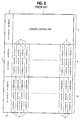
- the base station apparatus of a conventional time-division multiple access (TDMA) cellular mobile communication system is comprised of a common control unit 1 which is connected to a mobile telephone switching office, not shown, to provide overall control of the base station.
- Common control unit 1 is powered by a power supply unit 2 and mounted on an upper shelf 3 of the apparatus frame with the power supply unit 2 .
- the base station serves two cells to which frequency ranges 1.5 GHz and 800 MHz, for example, are assigned respectively.
- a plurality of radio transceiver panels 4 are provided which are connected to the common control unit 1 and commonly powered by a power supply unit 5 .
- Each transceiver panel 4 has a bandwidth of 0.25 MHz in the 1.5-GHz range and three time slots are multiplexed in the 0.25 MHz band of each transceiver.
- the transcelver panels 4 and power supply unit 5 are both mounted side by side on a middle shelf 6 .
- the output terminal of each transceiver panel 4 is connected to a frequency division multiplexer 7A where it is multiplexed with the outputs of other transceivers and supplied to a diplexer 9A and transmitted from antenna 10A.
- Signals from mobile units located in the 1.5-GHz range cell are received by antenna 10 and fed through diplexer 9A to a frequency division demultiplexer 8A where they are decomposed into individual frequency signals and supplied respectively to transceiver panels 4 .
- a plurality of radio transceivers 14 are provided which are connected to the control unit 1 , powered by a power supply unit 15 and mounted side by side on a lower shelf 16 .
- Each transceiver panel 14 has a bandwidth of 0.25 MHz in the 800-MHz range and three time slots are multiplexed in the 0.25 MHz band of each transceiver.
- the output terminal of each transceiver panel 14 is connected to a frequency division multiplexer 7B where it is multiplexed with the outputs of other transceivers 14 and supplied to a diplexer 9B and transmitted from antenna 10B .
- Signals from mobile units located in the 800-MHz range cell zone are received by antenna 10B and fed through diplexer 9B to a frequency demultiplexer 8B where they are decomposed into individual frequency signals and supplied respectively to transceiver panels 14.
- the control unit 1 receives an Incoming call from the MTSO and, in response, selects one of the transceivers and one of the time slots assigned to it, depending on the destination address of the incoming call, and operates the selected transceiver for transmission to a mobile station.
- a signal sent from the mobile station is received through demultiplexer 8A by the selected transceiver and applied through control unit 1 to the MTSO.
- a base station apparatus for a cellular mobile communication system in which different frequency ranges are assigned respectively to cells and the base station apparatus serves first and second cells.
- the apparatus comprises a first plurality of transceivers operating in a first radio frequency range assigned to the first cell and receiving power from a first power supply unit, a second plurality of transceivers operating in a second radio frequency range assigned to the second cell and receiving power from the first power supply unit, a third plurality of transceivers operating in the first radio frequency range and receiving power from a second power supply unit, and a fourth plurality of transceivers operating in the second radio frequency range and receiving power from the second power supply unit.
- the outputs of the first and third pluralities of transceivers are combined and transmitted from a first antenna and a signal in the first frequency range received by the first antenna is decomposed into first. frequency range individual signals and coupled to the first and third pluralities of transceivers.
- the outputs of the second and fourth pluralities of transceivers are, on the other hand, combined and transmitted from a second antenna, and a signal in the second frequency range received by the second antenna is decomposed into second frequency range individual signals and coupled to the second and fourth pluralities of transceivers.
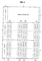
- a base-station apparatus of the present invention wherein parts corresponding to those in Figs. 1 and 2 are indicated by the same numerals as used in Figs. 1 and 2 and operate in the same manner as described previously. It is seen in Fig. 2 that on the middle shelf 6 a group of 1.5-GHz range transceiver panels 34A and a group of 800-MHz range transceiver panels 34B are mounted side by side and on the lower shelf 16 a group of 1.5-GHz range transceiver panels 44A and a group of 800-MHz range transceiver panels 44B are mounted side by side.
- All transceiver panels 34A and 34B on shelf 6 are commonly powered by the power supply unit 5 and all transceiver panels 44A and 44B on shelf 16 are commonly powered by the power supply unit 15 .
- Each of the transceivers 34A and 44A has a bandwidth of 0.25 MHz in the 1.5 GHz range, and each of the transceivers 34B and 44B has a bandwidth of 0.25 MHz in the 800 MHz range.
- Three time slots are multiplexed into the 0.25-MHz band of each of the transceivers 34A , 34B , 44A and 44B .
- the outputs of all 1.5-GHz range transceivers 34A and 44A are connected to frequency division multiplexer 7A , while the outputs of all 800-MHz range transceivers 34B and 44B are connected to frequency division multiplexer 7B .
- the 1.5-GHz range signals received by antenna 10A are coupled through diplexer 9A to frequency division demultiplexer 8A where they are demultiplexed into individual frequency signals in the 1.5-GHz range.
- These 1.5-GHz time-slot signals are coupled respectively to the transceiver panels 34A on middle shelf 6 and transceiver panels 44A on lower shelf 16 .
- the 800-MHz range signals received by antenna 10B are coupled through diplexer 9B to frequency division demultiplexer 8B where they are demultiplexed into individual frequency signals in the 800-MHz range, which are coupled respectively to the transceiver panels 34B on shelf 6 and transceiver panels 44B on shelf 16 .
- Control unit 1 monitors the power supply units 5 and 15 to isolate those transceivers from the system whose associated power supply unit has failed.
- control unit 1 makes a search through all the transceivers on shelves 6 and 16 for an idle one in response to receipt of an incoming call from the MTSO, not shown.
- control unit 1 isolates them from the system and makes a search exclusively through the transceivers on shelf 16 for an idle transceiver. Since the power supply unit 15 still supports the 1.5 GHz and 800 MHz range transceivers on shelf 16 , total service breakdown of one of the cell zones is prevented.
Landscapes
- Engineering & Computer Science (AREA)
- Computer Networks & Wireless Communication (AREA)
- Signal Processing (AREA)
- Mobile Radio Communication Systems (AREA)
Abstract
Description
- The present invention relates generally to cellular mobile communication systems and more specifically to a base station apparatus of the system.
- As illustrated in Figs. 1 and 2, the base station apparatus of a conventional time-division multiple access (TDMA) cellular mobile communication system is comprised of a
common control unit 1 which is connected to a mobile telephone switching office, not shown, to provide overall control of the base station.Common control unit 1 is powered by apower supply unit 2 and mounted on anupper shelf 3 of the apparatus frame with thepower supply unit 2. The base station serves two cells to which frequency ranges 1.5 GHz and 800 MHz, for example, are assigned respectively. To serve the 1.5-GHz range cell, a plurality ofradio transceiver panels 4 are provided which are connected to thecommon control unit 1 and commonly powered by a power supply unit 5. Eachtransceiver panel 4 has a bandwidth of 0.25 MHz in the 1.5-GHz range and three time slots are multiplexed in the 0.25 MHz band of each transceiver. Thetranscelver panels 4 and power supply unit 5 are both mounted side by side on amiddle shelf 6. The output terminal of eachtransceiver panel 4 is connected to afrequency division multiplexer 7A where it is multiplexed with the outputs of other transceivers and supplied to adiplexer 9A and transmitted fromantenna 10A. Signals from mobile units located in the 1.5-GHz range cell are received by antenna 10 and fed throughdiplexer 9A to afrequency division demultiplexer 8A where they are decomposed into individual frequency signals and supplied respectively totransceiver panels 4. To serve the 800-MHz range cell zone, a plurality ofradio transceivers 14 are provided which are connected to thecontrol unit 1, powered by apower supply unit 15 and mounted side by side on alower shelf 16. Eachtransceiver panel 14 has a bandwidth of 0.25 MHz in the 800-MHz range and three time slots are multiplexed in the 0.25 MHz band of each transceiver. The output terminal of eachtransceiver panel 14 is connected to a frequency division multiplexer 7B where it is multiplexed with the outputs ofother transceivers 14 and supplied to adiplexer 9B and transmitted from antenna 10B. Signals from mobile units located in the 800-MHz range cell zone are received by antenna 10B and fed throughdiplexer 9B to afrequency demultiplexer 8B where they are decomposed into individual frequency signals and supplied respectively totransceiver panels 14. Thecontrol unit 1 receives an Incoming call from the MTSO and, in response, selects one of the transceivers and one of the time slots assigned to it, depending on the destination address of the incoming call, and operates the selected transceiver for transmission to a mobile station. In return, a signal sent from the mobile station is received throughdemultiplexer 8A by the selected transceiver and applied throughcontrol unit 1 to the MTSO. - If any one of the
power supply units 5 and 15 should fail, all transceivers powered by the failed power supply become inoperative and service breakdown occurs in the cell served by the failed transceivers. - It is therefore an object of the present invention to provide a base station apparatus which prevents the total service breakdown of a cell zone due to power failure.
- According to the present invention, there is provided a base station apparatus for a cellular mobile communication system in which different frequency ranges are assigned respectively to cells and the base station apparatus serves first and second cells. The apparatus comprises a first plurality of transceivers operating in a first radio frequency range assigned to the first cell and receiving power from a first power supply unit, a second plurality of transceivers operating in a second radio frequency range assigned to the second cell and receiving power from the first power supply unit, a third plurality of transceivers operating in the first radio frequency range and receiving power from a second power supply unit, and a fourth plurality of transceivers operating in the second radio frequency range and receiving power from the second power supply unit. The outputs of the first and third pluralities of transceivers are combined and transmitted from a first antenna and a signal in the first frequency range received by the first antenna is decomposed into first. frequency range individual signals and coupled to the first and third pluralities of transceivers. The outputs of the second and fourth pluralities of transceivers are, on the other hand, combined and transmitted from a second antenna, and a signal in the second frequency range received by the second antenna is decomposed into second frequency range individual signals and coupled to the second and fourth pluralities of transceivers.
- The present invention will be described in further detail with reference to the accompanying drawings, in which:
- Fig. 1 is a block diagram of a prior art base station apparatus of a time-division multiple access cellular mobile communication system;
- Fig, 2 is a front view of a frame in which the prior art base station apparatus is mounted;
- Fig. 3 is a block diagram of a base station apparatus of a time-division multiple access cellular mobile communication system according to the present invention; and
- Fig. 4 is a front view of a frame in which the base station apparatus of the present invention is mounted.
- Referring now to Figs. 3 and 4, there is shown a base-station apparatus of the present invention wherein parts corresponding to those in Figs. 1 and 2 are indicated by the same numerals as used in Figs. 1 and 2 and operate in the same manner as described previously. It is seen in Fig. 2 that on the middle shelf 6 a group of 1.5-GHz
range transceiver panels 34A and a group of 800-MHzrange transceiver panels 34B are mounted side by side and on the lower shelf 16 a group of 1.5-GHzrange transceiver panels 44A and a group of 800-MHzrange transceiver panels 44B are mounted side by side. Alltransceiver panels shelf 6 are commonly powered by the power supply unit 5 and alltransceiver panels shelf 16 are commonly powered by thepower supply unit 15. Each of thetransceivers transceivers transceivers - The outputs of all 1.5-
GHz range transceivers frequency division multiplexer 7A, while the outputs of all 800-MHz range transceivers antenna 10A are coupled throughdiplexer 9A tofrequency division demultiplexer 8A where they are demultiplexed into individual frequency signals in the 1.5-GHz range. These 1.5-GHz time-slot signals are coupled respectively to thetransceiver panels 34A onmiddle shelf 6 andtransceiver panels 44A onlower shelf 16. On the other hand, the 800-MHz range signals received by antenna 10B are coupled throughdiplexer 9B tofrequency division demultiplexer 8B where they are demultiplexed into individual frequency signals in the 800-MHz range, which are coupled respectively to thetransceiver panels 34B onshelf 6 andtransceiver panels 44B onshelf 16. -
Control unit 1 monitors thepower supply units 5 and 15 to isolate those transceivers from the system whose associated power supply unit has failed. - During normal operation,
control unit 1 makes a search through all the transceivers onshelves - If the power supply unit 5 should fail, all transceivers on
shelf 6 becomes inactive, andcontrol unit 1 isolates them from the system and makes a search exclusively through the transceivers onshelf 16 for an idle transceiver. Since thepower supply unit 15 still supports the 1.5 GHz and 800 MHz range transceivers onshelf 16, total service breakdown of one of the cell zones is prevented.
Claims (3)
- A base station apparatus for a cellular mobile communication system in which different frequency ranges are assigned respectively to cell zones and the base station apparatus serves first and second cell zones, comprising;
a first power supply unit;
a first plurality of transceivers operating in a first radio frequency range assigned to the first cell zone and receiving power from said first power supply unit;
a second plurality of transceivers operating in a second radio frequency range assigned to the second cell zone and receiving power from said first power supply unit;
a second power supply unit;
a third plurality of transceivers operating in said first radio frequency range and receiving power from said second power supply unit;
a fourth plurality of transceivers operating in said second radio frequency range and receiving power from said second power supply unit;
first combining means for combining outputs of said first and third pluralities of transceivers and transmitting the combined outputs from a first antenna;
first decomposing means for decomposing a signal in said first frequency range received by the first antenna into first frequency range individual signals and coupling the first frequency range Individual signals to said first and third pluralities of transceivers;
second combining means for combining outputs of said second and fourth pluralities of transceivers and transmitting the combined outputs from a second antenna; and
second decomposing means for decomposing a signal in said second frequency range received by the second antenna into second frequency range individual signals and coupling the second frequency range individual signals to said second and fourth pluralities of transceivers. - A base station apparatus as claimed in claim 1, wherein said first and second pluralities of transceivers and said first power supply unit are mounted on a first shelf, and said third and fourth pluralities of transceivers and said second power supply unit are mounted on a second shelf.
- A base station apparatus as claimed in claim 1, further comprising a control unit for monitoring said first and second power supply units, said control unit being connected to a mobile switching office and responsive to receipt of an incoming call therefrom for making a search through all of said transceiver for an idle transceiver when both of said power supply units are normally operating, making a search through said third and fourth pluralities of transceivers for an idle transceiver when said first power supply unit fails and making a search through said first and second pluralities of transceivers for an idle transceiver when said second power supply unit fails.
Applications Claiming Priority (2)
| Application Number | Priority Date | Filing Date | Title |
|---|---|---|---|
| JP4295024A JP2836405B2 (en) | 1992-11-04 | 1992-11-04 | Mobile communication base station transceiver |
| JP295024/92 | 1992-11-04 |
Publications (3)
| Publication Number | Publication Date |
|---|---|
| EP0596727A2 true EP0596727A2 (en) | 1994-05-11 |
| EP0596727A3 EP0596727A3 (en) | 1994-10-26 |
| EP0596727B1 EP0596727B1 (en) | 1999-03-03 |
Family
ID=17815345
Family Applications (1)
| Application Number | Title | Priority Date | Filing Date |
|---|---|---|---|
| EP93308808A Expired - Lifetime EP0596727B1 (en) | 1992-11-04 | 1993-11-04 | Cellular mobile base station apparatus |
Country Status (4)
| Country | Link |
|---|---|
| US (1) | US5430789A (en) |
| EP (1) | EP0596727B1 (en) |
| JP (1) | JP2836405B2 (en) |
| DE (1) | DE69323693T2 (en) |
Cited By (5)
| Publication number | Priority date | Publication date | Assignee | Title |
|---|---|---|---|---|
| WO1997016937A1 (en) * | 1995-11-02 | 1997-05-09 | Nokia Telecommunications Oy | Method and arrangement for inteference-protected power supply |
| WO1998056198A1 (en) * | 1997-06-06 | 1998-12-10 | Northern Telecom Limited | Wireless access for local exchange carriers |
| EP0714176A3 (en) * | 1994-11-23 | 2000-07-19 | Lucent Technologies Inc. | Base station |
| EP1763179A4 (en) * | 2005-04-07 | 2007-07-25 | Huawei Tech Co Ltd | INTEGRATIVE ACCESS SYSTEM FOR WIRELESS NETWORK AND CABLE |
| EP2352358A4 (en) * | 2008-10-27 | 2012-06-27 | Huawei Tech Co Ltd | COMMUNICATION SYSTEM, DEVICE, AND METHOD |
Families Citing this family (12)
| Publication number | Priority date | Publication date | Assignee | Title |
|---|---|---|---|---|
| JP3166796B2 (en) * | 1992-07-29 | 2001-05-14 | ソニー株式会社 | Cordless phone |
| US5682403A (en) * | 1995-05-04 | 1997-10-28 | Wavelink Communications | Spread spectrum communication network signal processor |
| JPH1023497A (en) * | 1996-06-13 | 1998-01-23 | At & T Corp | Cellular radio telephone system utilizing centralized base station |
| US5857144A (en) * | 1996-08-09 | 1999-01-05 | Ericsson, Inc. | In-band vehicular repeater for trunked radio system |
| US6047160A (en) * | 1996-08-29 | 2000-04-04 | Ericsson Inc. | Transportable base station for a trunked radio communication system |
| US6169880B1 (en) | 1996-10-16 | 2001-01-02 | Ericsson Inc. | Method and system of load sharing and prioritization of radio repeaters |
| US6018644A (en) * | 1997-01-28 | 2000-01-25 | Northrop Grumman Corporation | Low-loss, fault-tolerant antenna interface unit |
| US20060023656A1 (en) * | 2004-07-29 | 2006-02-02 | Anglin Richard L Jr | Interactive digital data broadcasting system |
| US6615024B1 (en) * | 1998-05-01 | 2003-09-02 | Arraycomm, Inc. | Method and apparatus for determining signatures for calibrating a communication station having an antenna array |
| US6490443B1 (en) | 1999-09-02 | 2002-12-03 | Automated Business Companies | Communication and proximity authorization systems |
| US6813505B2 (en) * | 2001-01-05 | 2004-11-02 | Skyworks Solutions, Inc. | Efficient and flexible communication device and system with base-to-base communication |
| US7340280B2 (en) * | 2004-02-26 | 2008-03-04 | Nokia Corporation | Method of configuring base station, and base station |
Family Cites Families (6)
| Publication number | Priority date | Publication date | Assignee | Title |
|---|---|---|---|---|
| JPS5292002A (en) * | 1976-01-28 | 1977-08-03 | Mitsubishi Heavy Ind Ltd | Preventing device from implosion in boiler |
| US5084891A (en) * | 1989-09-08 | 1992-01-28 | Bell Communications Research, Inc. | Technique for jointly performing bit synchronization and error detection in a TDM/TDMA system |
| US5212804A (en) * | 1990-08-02 | 1993-05-18 | Gte Airfone, Inc. | Communication system having multiple base stations and multiple mobile units |
| FI88660C (en) * | 1991-01-09 | 1993-06-10 | Nokia Telecommunications Oy | Radiosändarmottagarsystem |
| US5243598A (en) * | 1991-04-02 | 1993-09-07 | Pactel Corporation | Microcell system in digital cellular |
| USD342249S (en) | 1992-08-31 | 1993-12-14 | Motorola, Inc. | Enclosure for a multi-unit cellular base station |
-
1992
- 1992-11-04 JP JP4295024A patent/JP2836405B2/en not_active Expired - Fee Related
-
1993
- 1993-11-04 DE DE69323693T patent/DE69323693T2/en not_active Expired - Lifetime
- 1993-11-04 US US08/145,574 patent/US5430789A/en not_active Expired - Lifetime
- 1993-11-04 EP EP93308808A patent/EP0596727B1/en not_active Expired - Lifetime
Cited By (12)
| Publication number | Priority date | Publication date | Assignee | Title |
|---|---|---|---|---|
| EP0714176A3 (en) * | 1994-11-23 | 2000-07-19 | Lucent Technologies Inc. | Base station |
| WO1997016937A1 (en) * | 1995-11-02 | 1997-05-09 | Nokia Telecommunications Oy | Method and arrangement for inteference-protected power supply |
| AU712954B2 (en) * | 1995-11-02 | 1999-11-18 | Nokia Telecommunications Oy | Method and arrangement for inteference-protected power supply |
| US6009337A (en) * | 1995-11-02 | 1999-12-28 | Nokia Telecommunications Oy | Method and arrangement for interference-protected power supply |
| CN1086096C (en) * | 1995-11-02 | 2002-06-05 | 诺基亚电信公司 | Method and device for interference-protected power supply |
| WO1998056198A1 (en) * | 1997-06-06 | 1998-12-10 | Northern Telecom Limited | Wireless access for local exchange carriers |
| EP1763179A4 (en) * | 2005-04-07 | 2007-07-25 | Huawei Tech Co Ltd | INTEGRATIVE ACCESS SYSTEM FOR WIRELESS NETWORK AND CABLE |
| US8208971B2 (en) | 2005-04-07 | 2012-06-26 | Huawei Technologies Co., Ltd. | Integrated access system of wireless and wired network |
| EP2352358A4 (en) * | 2008-10-27 | 2012-06-27 | Huawei Tech Co Ltd | COMMUNICATION SYSTEM, DEVICE, AND METHOD |
| US8498659B2 (en) | 2008-10-27 | 2013-07-30 | Huawei Technologies Co. Ltd. | Communication system, apparatus and method |
| US8768416B2 (en) | 2008-10-27 | 2014-07-01 | Huawei Technologies Co., Ltd. | Communication system, apparatus and method |
| US9225410B2 (en) | 2008-10-27 | 2015-12-29 | Huawei Technologies Co., Ltd. | Communication system, apparatus and method |
Also Published As
| Publication number | Publication date |
|---|---|
| EP0596727B1 (en) | 1999-03-03 |
| DE69323693T2 (en) | 1999-07-01 |
| EP0596727A3 (en) | 1994-10-26 |
| DE69323693D1 (en) | 1999-04-08 |
| JP2836405B2 (en) | 1998-12-14 |
| US5430789A (en) | 1995-07-04 |
| JPH06152490A (en) | 1994-05-31 |
Similar Documents
| Publication | Publication Date | Title |
|---|---|---|
| US5430789A (en) | Cellular mobile base station apparatus for serving a first and second cell zones | |
| US5648962A (en) | Base station in a cellular radio system and a cellular radio system | |
| US6584116B1 (en) | Method of transmission in a UMTS mobile telephone network enabling preparation for handover to a GSM cell during a call in a UMTS cell | |
| US5748624A (en) | Method of time-slot allocation in a TDMA communication system | |
| AU663604B2 (en) | Multiple cavity tuning of a transmitter output in a communication system | |
| US5550898A (en) | Metallic macrocell/microcell interface | |
| US6360106B1 (en) | Base station for a radio communications system | |
| KR950013616B1 (en) | Signal Routing System and Signal Routing Device and Method | |
| EP0652644B1 (en) | Base station transmission-reception apparatus for cellular system | |
| HU215226B (en) | Two-way network | |
| US6898431B1 (en) | Dynamic channel allocation in a sectored cell of a cellular communication system | |
| CN101304279A (en) | Radio frequency extension apparatus and base station system | |
| EP0715786B1 (en) | Base station equipment using diversity reception | |
| WO1995006369A1 (en) | A method for adding capacity of a base station | |
| US6570844B1 (en) | System and method for providing redundancy in a telecommunications system | |
| EP1292159B1 (en) | Base station supporting multi-sector/multi-frequency assignment for seamles call service | |
| CN101355369A (en) | Transceiver, mobile terminal as well as method for processing transmission and receive | |
| EP0692163B1 (en) | Radio repeater | |
| US5887267A (en) | Bus arbitrators for common local oscillators in cellular radiotelephone base stations | |
| WO2008066214A1 (en) | Method and apparatus for managing sector of base station in mobile telecommunication systems | |
| JP3177481B2 (en) | Base station of mobile communication system | |
| KR20030022658A (en) | Base station system supporting multi-sector/multi-fa for call service seamless | |
| JPH0787418B2 (en) | Control channel configuration method | |
| WO1999007169A1 (en) | Trunked radio system using dual receiver architecture to improve efficiency, performance and access times | |
| JPH01220926A (en) | Multi-direction connection type digital subscriber radio system |
Legal Events
| Date | Code | Title | Description |
|---|---|---|---|
| PUAI | Public reference made under article 153(3) epc to a published international application that has entered the european phase |
Free format text: ORIGINAL CODE: 0009012 |
|
| AK | Designated contracting states |
Kind code of ref document: A2 Designated state(s): BE DE FR GB IT NL SE |
|
| PUAL | Search report despatched |
Free format text: ORIGINAL CODE: 0009013 |
|
| AK | Designated contracting states |
Kind code of ref document: A3 Designated state(s): BE DE FR GB IT NL SE |
|
| 17P | Request for examination filed |
Effective date: 19940915 |
|
| 17Q | First examination report despatched |
Effective date: 19971107 |
|
| GRAG | Despatch of communication of intention to grant |
Free format text: ORIGINAL CODE: EPIDOS AGRA |
|
| GRAG | Despatch of communication of intention to grant |
Free format text: ORIGINAL CODE: EPIDOS AGRA |
|
| GRAH | Despatch of communication of intention to grant a patent |
Free format text: ORIGINAL CODE: EPIDOS IGRA |
|
| GRAH | Despatch of communication of intention to grant a patent |
Free format text: ORIGINAL CODE: EPIDOS IGRA |
|
| GRAA | (expected) grant |
Free format text: ORIGINAL CODE: 0009210 |
|
| AK | Designated contracting states |
Kind code of ref document: B1 Designated state(s): BE DE FR GB IT NL SE |
|
| PG25 | Lapsed in a contracting state [announced via postgrant information from national office to epo] |
Ref country code: SE Free format text: THE PATENT HAS BEEN ANNULLED BY A DECISION OF A NATIONAL AUTHORITY Effective date: 19990303 Ref country code: NL Free format text: LAPSE BECAUSE OF FAILURE TO SUBMIT A TRANSLATION OF THE DESCRIPTION OR TO PAY THE FEE WITHIN THE PRESCRIBED TIME-LIMIT Effective date: 19990303 Ref country code: BE Free format text: LAPSE BECAUSE OF FAILURE TO SUBMIT A TRANSLATION OF THE DESCRIPTION OR TO PAY THE FEE WITHIN THE PRESCRIBED TIME-LIMIT Effective date: 19990303 |
|
| REF | Corresponds to: |
Ref document number: 69323693 Country of ref document: DE Date of ref document: 19990408 |
|
| ITF | It: translation for a ep patent filed | ||
| ET | Fr: translation filed | ||
| NLV1 | Nl: lapsed or annulled due to failure to fulfill the requirements of art. 29p and 29m of the patents act | ||
| PLBE | No opposition filed within time limit |
Free format text: ORIGINAL CODE: 0009261 |
|
| 26N | No opposition filed | ||
| REG | Reference to a national code |
Ref country code: GB Ref legal event code: IF02 |
|
| PGFP | Annual fee paid to national office [announced via postgrant information from national office to epo] |
Ref country code: IT Payment date: 20081127 Year of fee payment: 16 |
|
| PGFP | Annual fee paid to national office [announced via postgrant information from national office to epo] |
Ref country code: FR Payment date: 20081112 Year of fee payment: 16 |
|
| PGFP | Annual fee paid to national office [announced via postgrant information from national office to epo] |
Ref country code: GB Payment date: 20081029 Year of fee payment: 16 |
|
| PGFP | Annual fee paid to national office [announced via postgrant information from national office to epo] |
Ref country code: DE Payment date: 20091029 Year of fee payment: 17 |
|
| GBPC | Gb: european patent ceased through non-payment of renewal fee |
Effective date: 20091104 |
|
| REG | Reference to a national code |
Ref country code: FR Ref legal event code: ST Effective date: 20100730 |
|
| PG25 | Lapsed in a contracting state [announced via postgrant information from national office to epo] |
Ref country code: FR Free format text: LAPSE BECAUSE OF NON-PAYMENT OF DUE FEES Effective date: 20091130 |
|
| PG25 | Lapsed in a contracting state [announced via postgrant information from national office to epo] |
Ref country code: GB Free format text: LAPSE BECAUSE OF NON-PAYMENT OF DUE FEES Effective date: 20091104 |
|
| PG25 | Lapsed in a contracting state [announced via postgrant information from national office to epo] |
Ref country code: IT Free format text: LAPSE BECAUSE OF NON-PAYMENT OF DUE FEES Effective date: 20091104 |
|
| PG25 | Lapsed in a contracting state [announced via postgrant information from national office to epo] |
Ref country code: DE Free format text: LAPSE BECAUSE OF NON-PAYMENT OF DUE FEES Effective date: 20110531 |
|
| REG | Reference to a national code |
Ref country code: DE Ref legal event code: R119 Ref document number: 69323693 Country of ref document: DE Effective date: 20110601 Ref country code: DE Ref legal event code: R119 Ref document number: 69323693 Country of ref document: DE Effective date: 20110531 |