EP0596723B1 - Apparatus and method for producing color half-tone images - Google Patents
Apparatus and method for producing color half-tone images Download PDFInfo
- Publication number
- EP0596723B1 EP0596723B1 EP93308791A EP93308791A EP0596723B1 EP 0596723 B1 EP0596723 B1 EP 0596723B1 EP 93308791 A EP93308791 A EP 93308791A EP 93308791 A EP93308791 A EP 93308791A EP 0596723 B1 EP0596723 B1 EP 0596723B1
- Authority
- EP
- European Patent Office
- Prior art keywords
- macropixel
- dots
- image
- colors
- filling
- Prior art date
- Legal status (The legal status is an assumption and is not a legal conclusion. Google has not performed a legal analysis and makes no representation as to the accuracy of the status listed.)
- Expired - Lifetime
Links
Images


Classifications
-
- H—ELECTRICITY
- H04—ELECTRIC COMMUNICATION TECHNIQUE
- H04N—PICTORIAL COMMUNICATION, e.g. TELEVISION
- H04N1/00—Scanning, transmission or reproduction of documents or the like, e.g. facsimile transmission; Details thereof
- H04N1/46—Colour picture communication systems
- H04N1/52—Circuits or arrangements for halftone screening
-
- B—PERFORMING OPERATIONS; TRANSPORTING
- B41—PRINTING; LINING MACHINES; TYPEWRITERS; STAMPS
- B41J—TYPEWRITERS; SELECTIVE PRINTING MECHANISMS, i.e. MECHANISMS PRINTING OTHERWISE THAN FROM A FORME; CORRECTION OF TYPOGRAPHICAL ERRORS
- B41J2/00—Typewriters or selective printing mechanisms characterised by the printing or marking process for which they are designed
- B41J2/005—Typewriters or selective printing mechanisms characterised by the printing or marking process for which they are designed characterised by bringing liquid or particles selectively into contact with a printing material
- B41J2/01—Ink jet
- B41J2/205—Ink jet for printing a discrete number of tones
- B41J2/2054—Ink jet for printing a discrete number of tones by the variation of dot disposition or characteristics, e.g. dot number density, dot shape
Definitions
- the present invention relates to apparatus and techniques for producing color half-tone images generally and to apparatus and techniques for dot placement in particular.
- a pixel location can have up to four dots, which include the three subtractive primaries (eg. cyan, magenta and yellow) and black.
- the amount of colorant at a pixel location can be varied by altering the number of droplets in a dot and the number of dots in a pixel.
- the positioning of dots on a printing medium can also increase the range of colors printed. This can be achieved by placing dots in a matrix of pixels referred to as a "macropixel.”
- the macropixel is typically a square multiplicity of pixels (e.g. 2 X 2, 4 X 4) or alternatively, it can be a rectangular multiplicity of pixels (e.g. 2 X 4).
- a macropixel filling method can be designed which determines the dot size and the dot positioning required to produce various shades (i.e. grey levels) of a given color.
- U.S. Patent 4,367,482 to Heinzl describes a method and apparatus for representing polychromatic half-tone images employing the formation of image spots (i.e. dots) of equal size.
- the U.S. Patent 3,977,007 to Berry et al. describes a monochrome method for placing the dots on the paper utilizing a 4x4 matrix (i.e. 16 pixel locations) for each macropixel. Sixteen incremental macropixel fill patterns are defined, defining 16 grey levels. Darker colors are produced by increasing the number of droplets per dot at each pixel location.
- the locations in a 4x4 macropixel are typically numbered as follows: 1 2 3 4 5 6 7 8 9 10 11 12 13 14 15 16 where the raster line or printing line moves horizontally across the macropixel matrix. Thus, the dots 1, 2, 3 and 4 are printed first and the other rows follow.
- a conventional macropixel filling method for a 4x4 macropixel follows the form of a Bayer, or dispersed dot, pattern which is typically used for output devices which print discrete dot sizes.
- An example pattern is: 1 9 3 11 13 5 15 7 4 12 2 10 16 8 14 6 where the macropixel is filled in the order indicated.
- a 4x4 macropixel having a grey level of 3 would have the pixel locations marked 1 - 3 filled with a dot and a macropixel with a grey level of 4 would have the pixel locations marked 1 4 filled with a dot.
- Fig. 1A A typical image which displays an image defect known as rainbowing, is illustrated in Fig. 1A.
- Fig. 1B A simplified enlarged illustration of parts of the image of Fig. 1A appears in Fig. 1B.
- the dot size is such that there exists some white space 16 surrounding the dots 10 and 12. In this situation, the density of the black dot 10 partially or completely hides the color of the other dot 12 and the amount of white space between each pixel 14.
- the color defects produced by the misregistration shown in Fig. 1B may be classified as follows:
- types I and II produce one-dimensional moire patterns which are noticeable in the color print, as seen in Fig. 1A.
- the defects are only produced with colors ranging from those which have white highlights (i.e. white spaces 16) to midtones. The defects are not noticeable when the printing dot color is dark enough that the entire printing dot space is covered with ink.
- Color to color misregistration is typically caused by inaccuracies in the electro-mechanical design and/or manufacture of the printer.
- One particular cause is the inaccuracy of the gearbox and drive mechanism, including pulleys, belts, worm gears and lead screws.
- the variation in the gear operation will produce different frequencies of rainbowing.
- an object of the present invention to provide a method for improving resistance to image defects resulting from color to color misregistration without having to significantly change the design or manufacturing process of the printer.
- the present invention seeks to minimize moire (types I and II), and to improve image repeatability from image to image on a single printer and image uniformity between different printers of the same type.
- direct digital printing apparatus for producing a color half-tone image from a digital data file comprising a macropixel filler for constructing a pattern of dots for each of a plurality of colors, characterised in that for data values less than a predetermined value, corresponding to a predefined input density, the macropixel filler operates according to a first macropixel filling algorithm and for data a values equal to or above said predetermined value the macropixel filler operates according to a second macropixel filling algorithm having a plurality of dot positions different from said first macropixel filling algorithm for all operative data values.
- the macropixel filler produces a plurality of multiple droplet dots in less than the total available pixel locations in a macropixel over at least part of a range of input densities.
- direct digital printing apparatus for producing a color half-tone image from a digital data file and including a macropixel filler which maintains, for a given input density, an amount of unprinted area within a macropixel generally uniform notwithstanding misregistration between different colors.
- direct digital printing apparatus for producing a color half-tone image from a digital data file and comprising a macropixel filler for maintaining the fractional areas of all colors and combinations thereof within each dot generally uniform over the image notwithstanding misregistration between different colors.
- ink jet printing apparatus for producing a color half-tone image from a digital data file including a macropixel filler for constructing a pattern of dots for each of a plurality of colors, wherein the configuration of the dots varies as a function of the input density of each of the plurality of colors.
- the dots are of variable size as a function of the number of droplets deposited at the pixel locations.
- increasing input density values are mapped by adding additional droplets to both uncolored and colored pixel locations in the macropixel in an alternating manner.
- the invention also provides a method for producing a color half-tone image according to claim 8 below.
- the invention further provides a printing medium bearing a half-tone image inaccordance with claim 15 below.
- each macropixel is formed of a 4x4 matrix of pixels and each dot at each pixel location can be formed of up to 31 (in the illustrated embodiment) droplets of ink. Therefore, there are 496 possible grey levels for each color of ink.
- a square or otherwise shaped pixel matrix of any other suitable dimensions may be employed.
- the maximum number of droplets need not be 31 but rather depends on the mechanism which produces the droplets.
- the grey levels are divided as follows: 0 - 72, 73 - 256 and 257 - 496 and one dot placement method is operative for each range. Alternatively, more or less than 3 ranges may be employed, or three different ranges may be employed.
- the first macropixel filling method fills only half of the 16 pixel locations in any macropixel matrix and places the dots such that they provide pseudo screen angles. Alternatively, it is believed that the first macropixel filling method may be employed to fill some other proportion of the macropixel matrix pixel locations, such as 40% thereof.
- Figs. 2A - 2H provide example dot placement matrices for the following screen angles: 0 degrees, 26 degrees, 45 degrees, 64 degrees, 90 degrees,116 degrees, 135 degrees and 154 degrees. The patterns of the macropixel matrices are utilized until there are 9 droplets of ink in each dot at each pixel location; in other words, for grey levels 1 - 72.
- sample matrices of Figs. 2A - 2H are only one possible set of matrices.
- any suitable permutation of the correspondence between screen angles and matrices in Figs. 2A - 2H may be employed, such as the permutation defined by the additional set of sample dot placement matrices illustrated in Figs. 9A - 9H.
- any suitable filling order may replace the filling order indicated.
- the filling order for matrix 2C might, alternatively, be as follows: 0 7 0 4 1 0 5 0 0 3 0 8 6 0 2 0
- the primary fill areas may be rotated by 90 or 180 degrees in either direction and/or the locations of the primary and secondary fill areas may be interchanged.
- Fig. 3 shows the filling of the macropixel matrix of Fig. 2F for grey levels 1 - 16.
- Light grey dots, labeled 20, indicate one droplet of ink and darker grey dots, labeled 22, indicate two droplets of ink.
- the 16th grey level preferably does not completely fill the macropixel matrix. In fact, this is preferably true for all grey levels within the first range.
- the plurality of macropixel matrices can be used in a single print.
- the matrices can be used in a pseudo-random fashion, where each pixel is printed with a different one of the available macropixel matrices.
- different colors can be printed with different ones of the matrices.
- cyan and magenta are both printed, but with different pseudo screen angles.
- cyan is printed with a pseudo screen angle of 135 degrees and magenta has a screen angle of 26 degrees.
- Each ink is placed with no regard to the presence or absence of the other ink. For those pixel locations which are part of both macropixel matrices, the color therein is a combination of the two colors.
- the first macropixel filling method causes edge raggedness in areas with larger sized dots and thus is unsuitable for use with linework and high image density image areas. Therefore, for large dot size, typically dot sizes greater than 9 droplets of ink per pixel location, another macropixel filling method is preferably employed, such as the second macropixel filling method shown and described herein.
- the entire 4x4 matrix comes to be filled with ink.
- the macropixel matrices of Figs. 2A-2H are each separated into two areas, the primary fill area, comprising the portion of each matrix of Figs. 2A-2H which is filled by the first macropixel method, and the secondary fill area, comprising the remaining pixel locations.
- the secondary fill area has an order of filling.
- the order, for each of the macropixel matrices of Figs. 2A-2H, is respectively given in Figs. 5A - 5H.
- FIG. 6A and 6B illustrate a preferred filling method for the macropixel matrices of Figs. 2F and 5F, for grey levels 73 - 104.
- the dots in Figs. 6A and 6B are labeled as follows:
- the method covering all grey levels from 73 to 256, preferably comprises the following steps:
- the third macropixel filling method operative for grey levels above 256, may for example utilize the Bayer macro-pixel matrix described hereinabove, although, alternatively, any other suitable method may be employed.
- Fig. 7 shows the filling method for grey levels 257 - 272, where the dots labeled 50 have 16 droplets and the dots labeled 52 have 17 droplets.
- the methods described hereinabove are utilized to build a plurality of droplet location tables, one for each pseudo screen angle.
- the macropixel filling method utilizes the droplet location tables to determine, for each ink color, the placement of and the number of droplets per dot for each grey level provided to it.
- the macropixel filling method can pseudo randomly select a droplet location table to provide the corresponding information regarding the placement of each droplet within the macropixel.
- one droplet location table can be associated with each ink color; in which case, the macropixel filling method operates with a maximum of four droplet location tables for a given print.
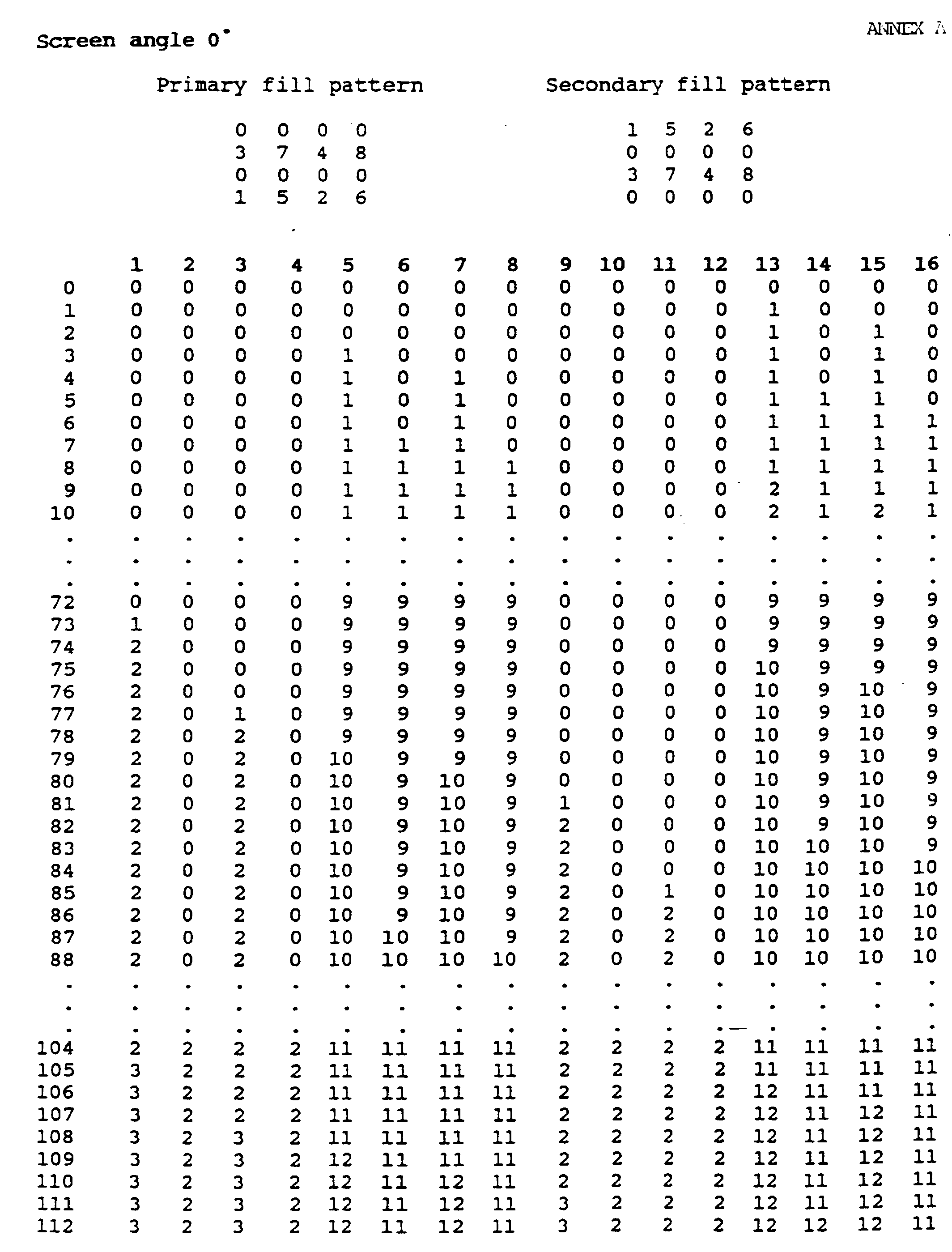
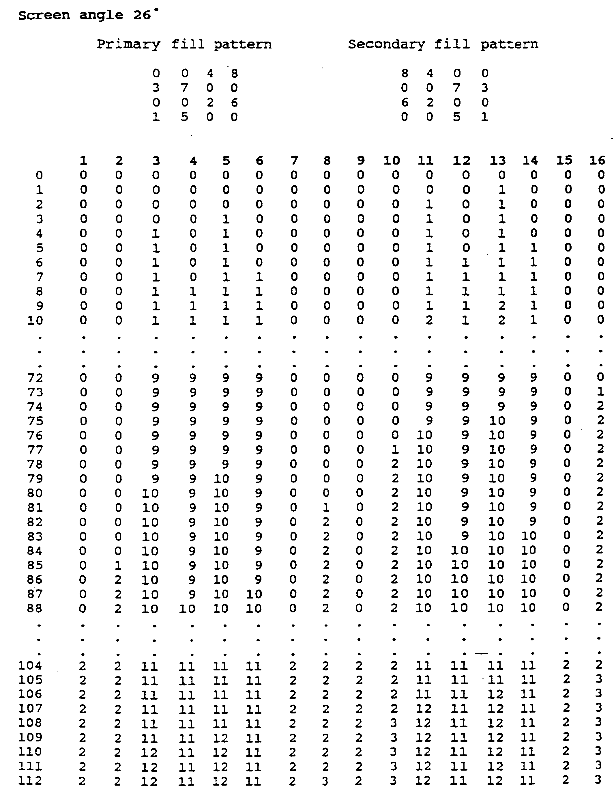
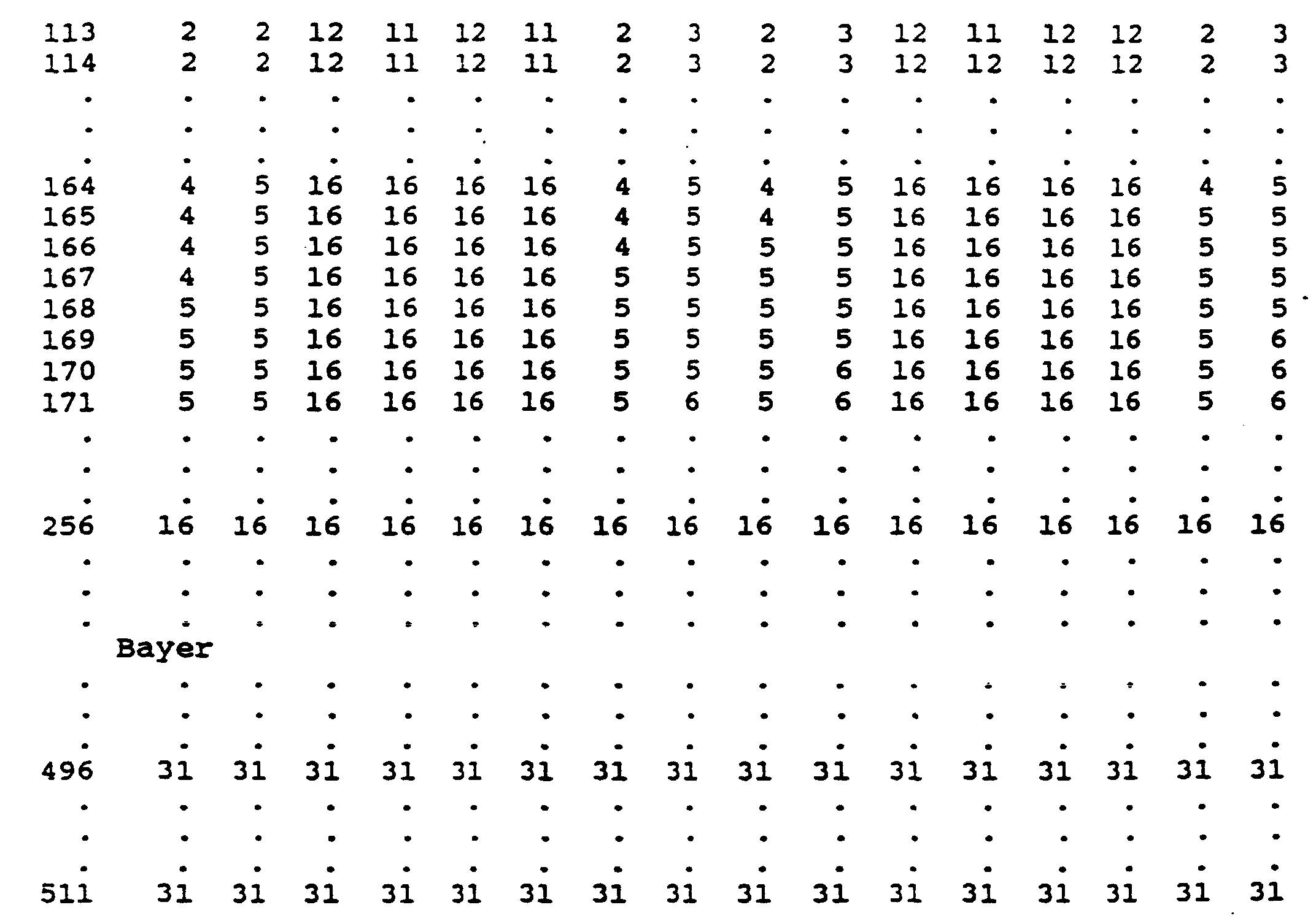
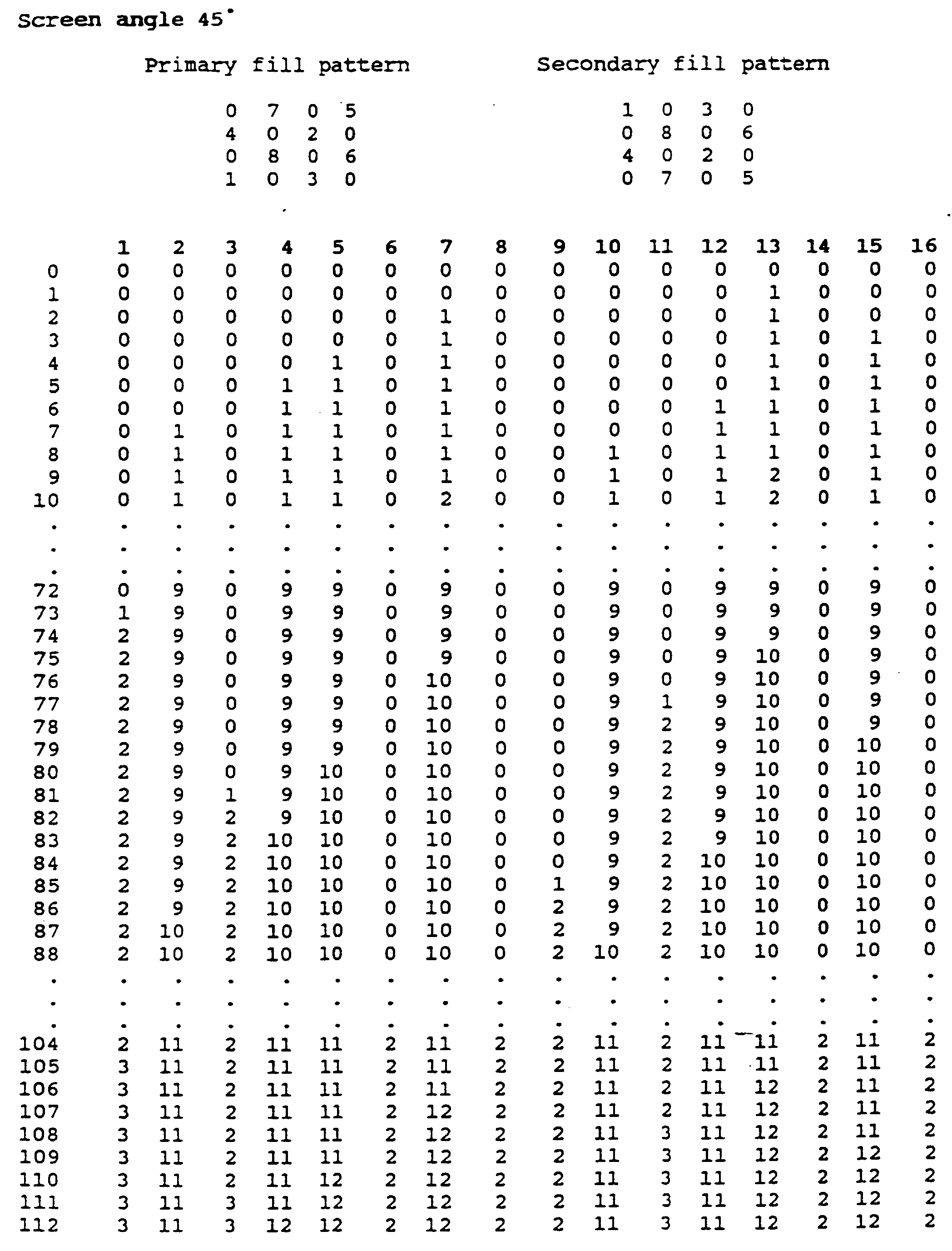
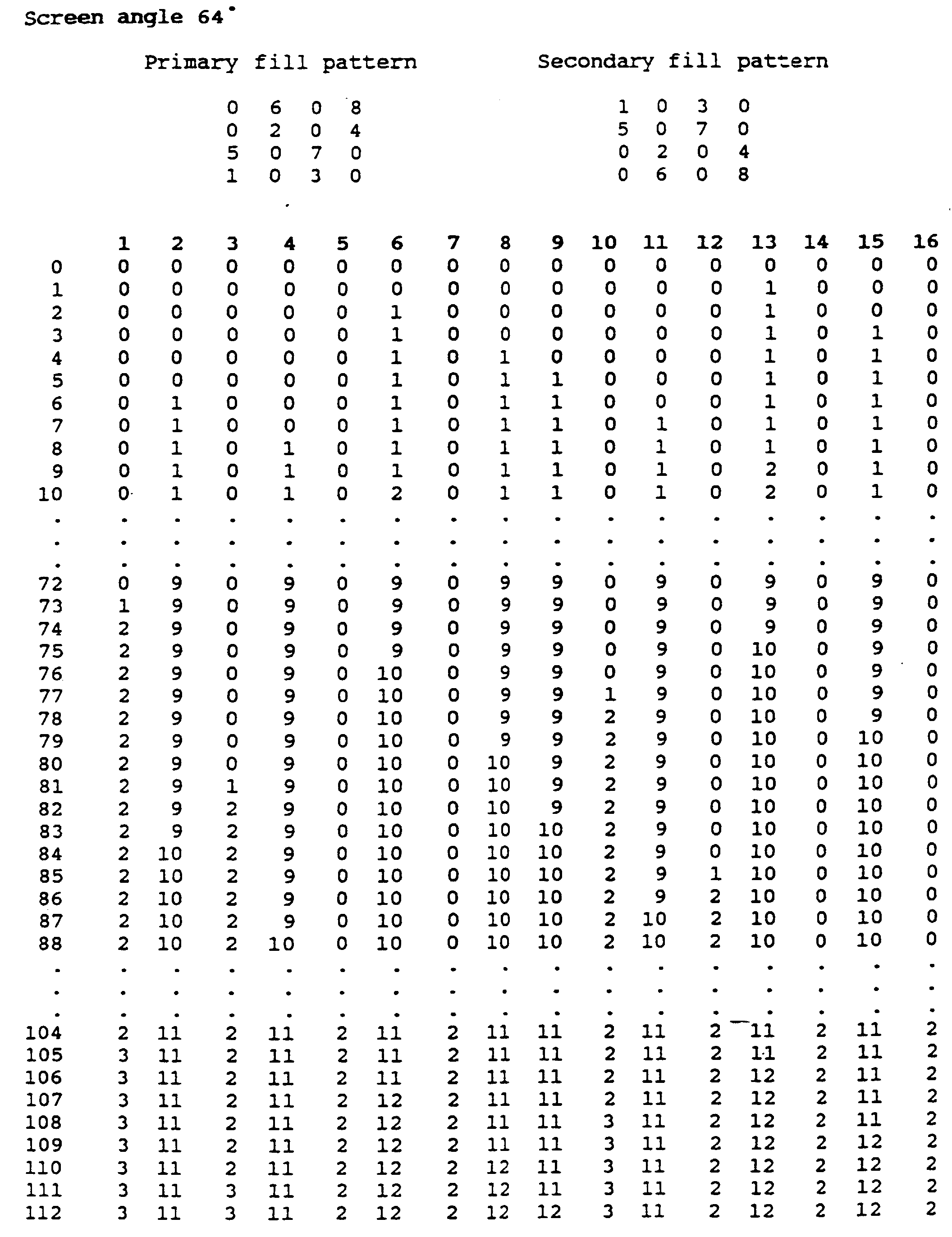
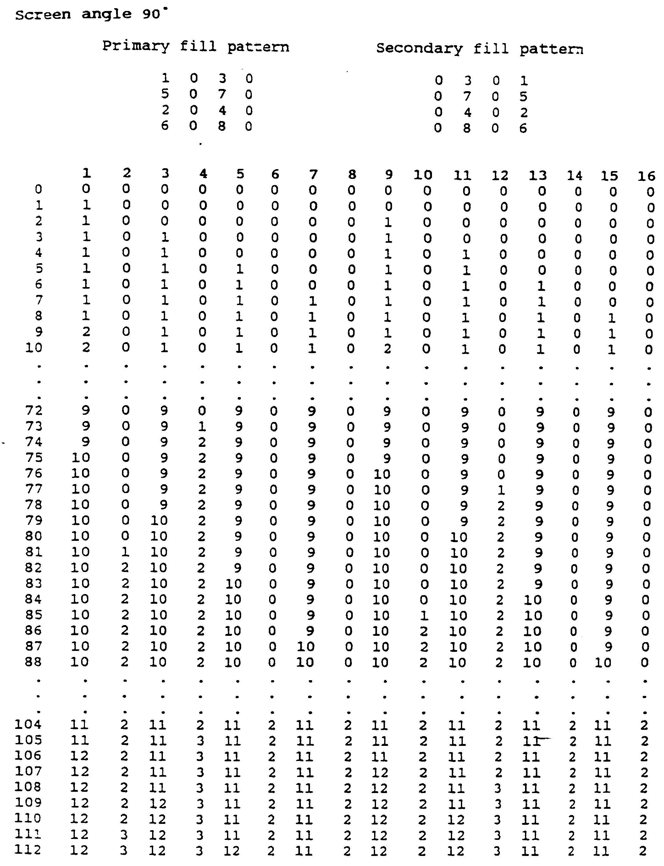
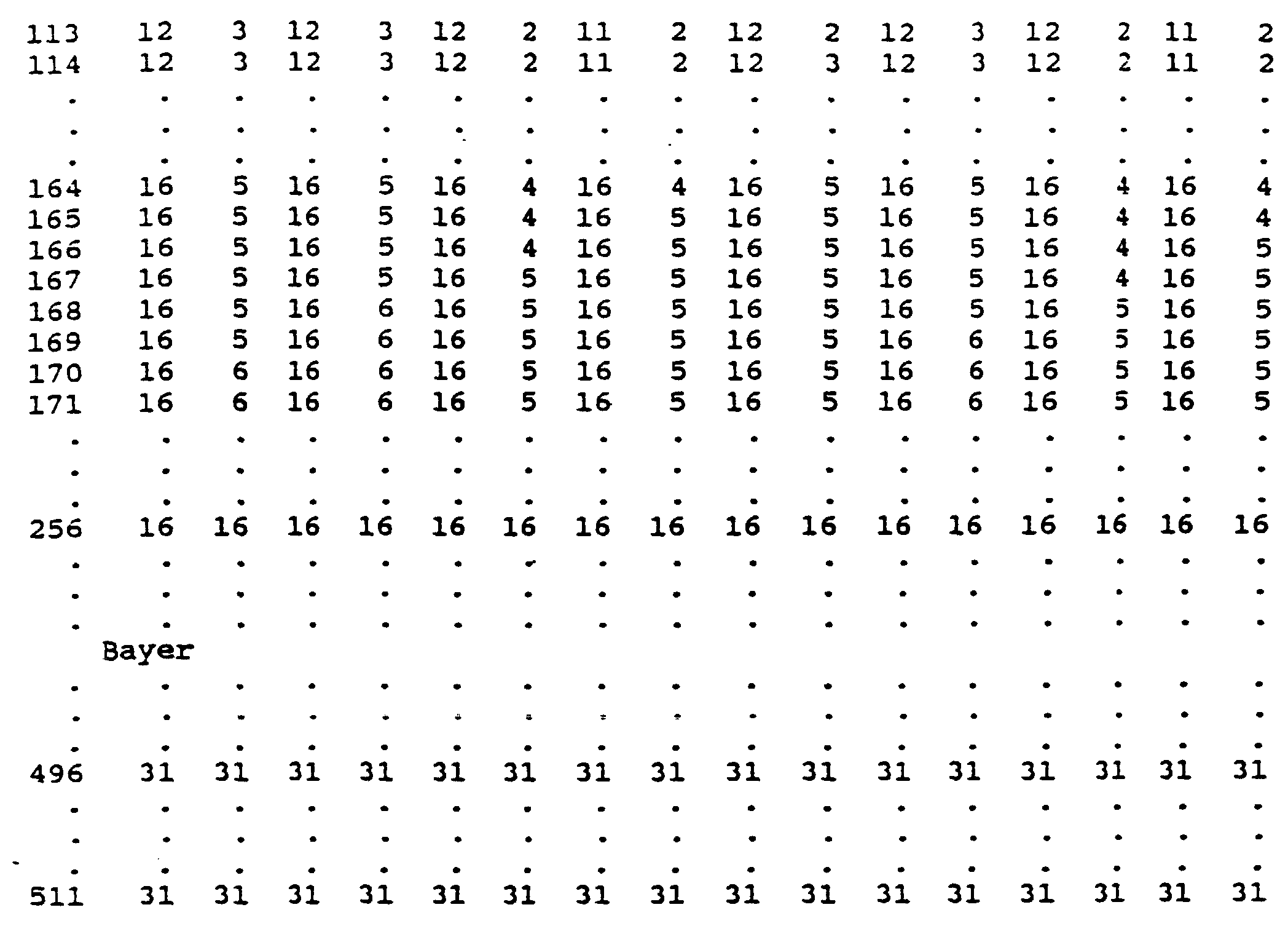
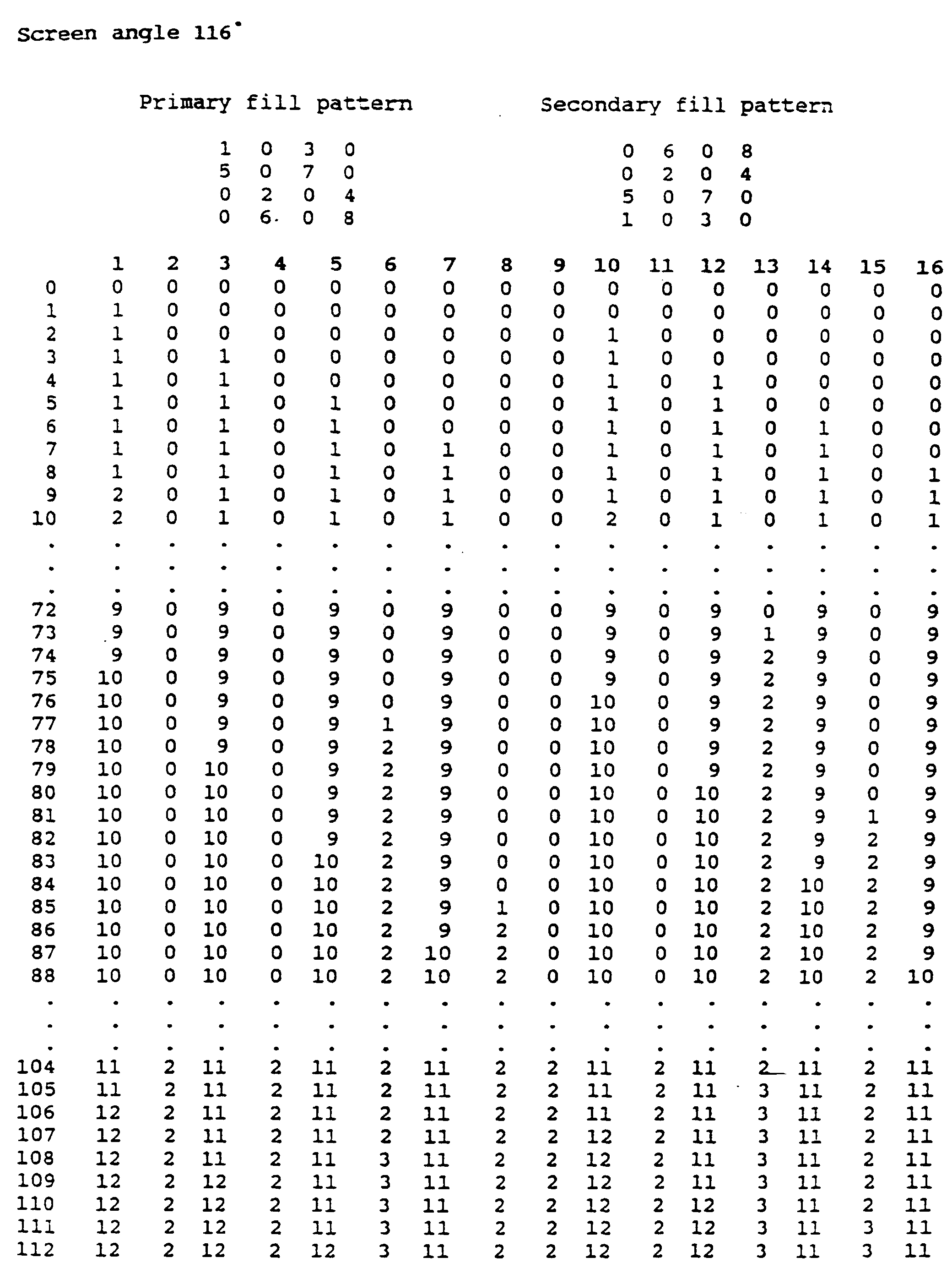
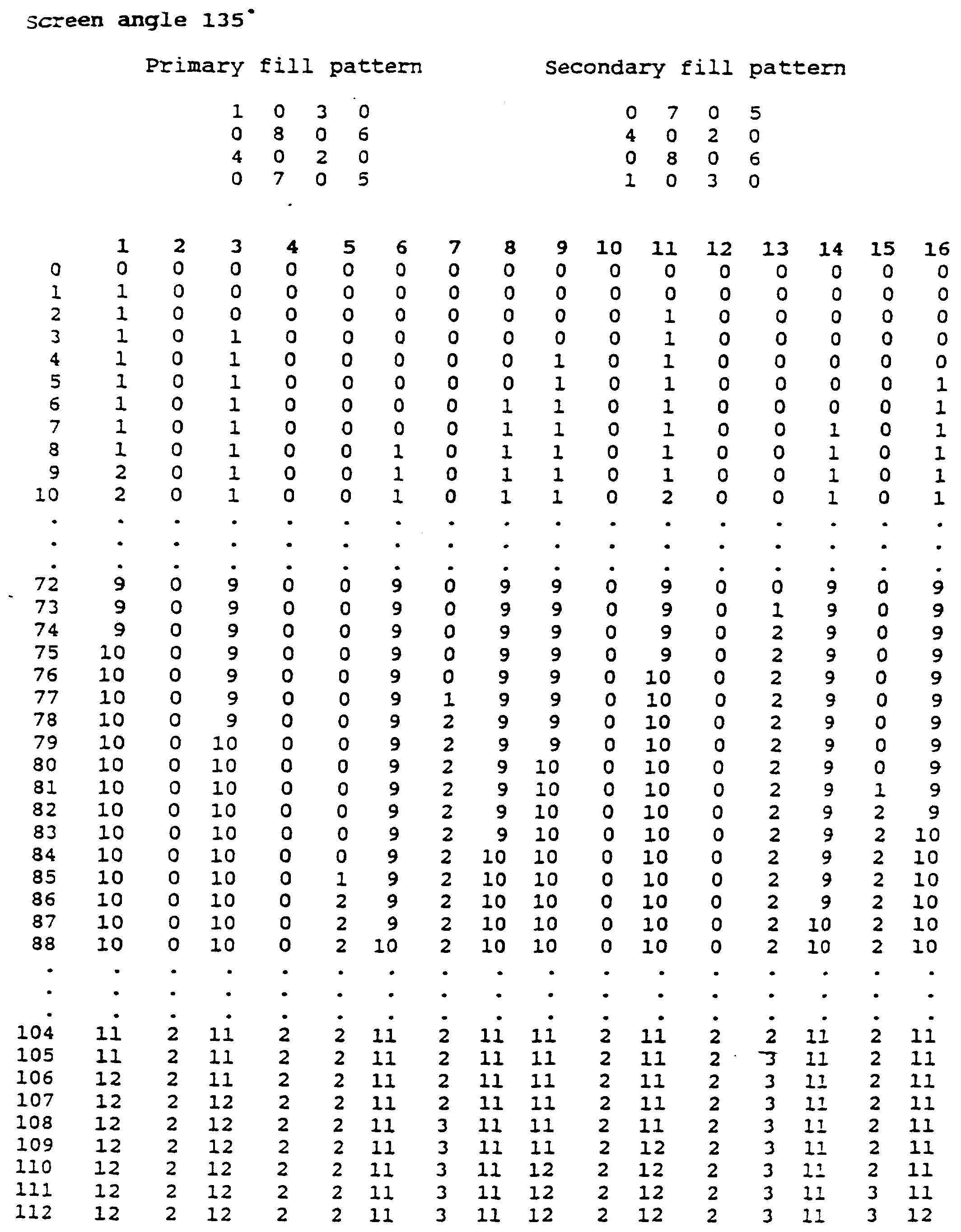
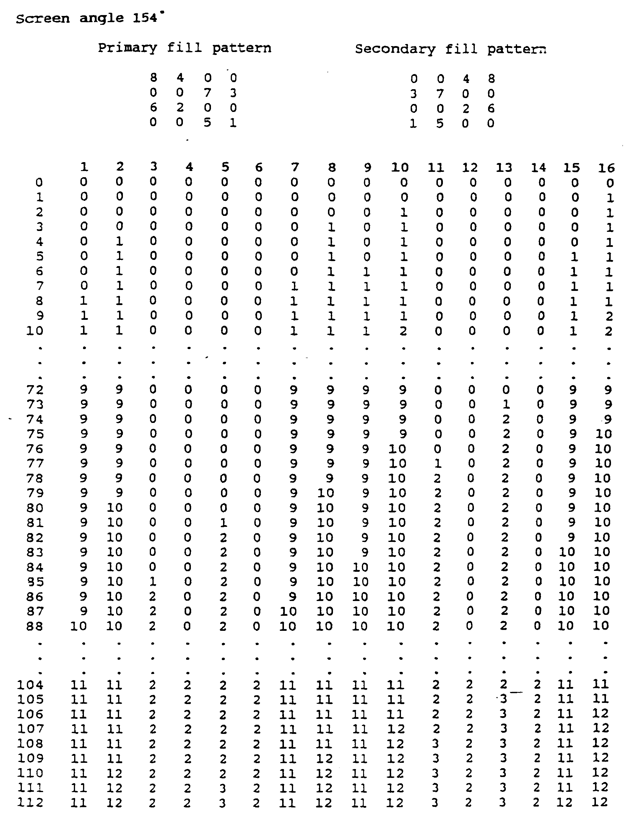
- Annex A is a numeric representation of a preferred macropixel filling method for each of the pseudo screen angles of Figs. 2A-2H.
- the vertical scale indicates the total number of droplets in the 4x4 matrix and the horizontal scale indicates the 4x4 pixel location as described hereinabove in the Background of the Invention.
- the values in the table represent the number of droplets at a given pixel location. The entire table is not provided; it being understood that the macropixel pattern preceding any empty sections of the table is continued until the next nonempty portion of the table.
- the present invention typically maintains, for a given input density, an amount of unprinted area within a macropixel which is generally uniform notwithstanding misregistration between different colors. Furthermore, it typically maintains the fractional areas of all colors and combinations thereof within each printing dot generally uniform over the image notwithstanding misregistration.
- Fig. 8 illustrates the image of Fig. 1A produced in accordance with a preferred embodiment of the present invention and shows the effectiveness of the present invention in preventing rainbowing.
Landscapes
- Engineering & Computer Science (AREA)
- Multimedia (AREA)
- Signal Processing (AREA)
- Color, Gradation (AREA)
- Ink Jet (AREA)
- Facsimile Image Signal Circuits (AREA)
- Dot-Matrix Printers And Others (AREA)
- Image Processing (AREA)
- Color Image Communication Systems (AREA)
Description
| 1 | 2 | 3 | 4 |
| 5 | 6 | 7 | 8 |
| 9 | 10 | 11 | 12 |
| 13 | 14 | 15 | 16 |
| 1 | 9 | 3 | 11 |
| 13 | 5 | 15 | 7 |
| 4 | 12 | 2 | 10 |
| 16 | 8 | 14 | 6 |
| 0 | 7 | 0 | 4 |
| 1 | 0 | 5 | 0 |
| 0 | 3 | 0 | 8 |
| 6 | 0 | 2 | 0 |
- 30
- 1 droplet of cyan
- 31
- 1 droplet of magenta
- 32
- 1 droplet cyan, 1 droplet magenta
- 33
- two droplets cyan, 1 droplet magenta
- 34
- 1 droplet cyan, two droplets magenta
- 35
- two droplets cyan
- 36
- two droplets magenta
- 37
- two droplets cyan, two droplets magenta
- 40
- 1 droplet
- 41
- 2 droplet
- 42
- 9 droplet
- 43
- 10 droplet
- 44
- 11 droplet






Claims (15)
- A digital printing apparatus for producing a color half-tone image from a digital data file comprising :
a macropixel filler for constructing a pattern of dots for each of a plurality of colors, characterised in that for data values less than a predetermined value, corresponding to a predefined input density, the macropixel filler operates according to a first macropixel filling algorithm and for data values equal to or above said predetermined value the macropixel filler operates according to a second macropixel filling algorithm having a plurality of dot positions different from said first macropixel filling algorithm for all operative data values. - A digital printing apparatus as claimed in claim 1, wherein said macropixel filler is operative for producing a plurality of multiple droplet dots in less than the total available pixel locations in a macropixel over at least part of a range of input densities.
- Apparatus according to claim 2, wherein within an intermediate range of input density values, increasing input density values are mapped by adding additional droplets to both uncolored and colored pixel locations in the macropixel in an alternating manner.
- A digital printing apparatus as claimed in claim 1, 2 or 3, wherein said macropixel filler maintains, for a given input density, an amount of unprinted area within a macropixel generally uniform notwithstanding misregistration between different colors.
- A digital printing apparatus as claimed in claim 2, 3 or 4, wherein said macro pixel filler maintains the fractional areas of all colors and combinations thereof within each dot generally uniform over the image notwithstanding misregistration between different colors.
- A digital printing apparatus as claimed in any one previous claim, wherein the apparatus comprising an ink jet printer and said macropixel filler constructing a pattern of dots for each of a plurality of colours, the configuration of the dots varying as a function of the input density of each of the plurality of colors.
- Apparatus as claimed in any one previous claim, wherein said dots are of variable size as a function of the number of droplets deposited at the pixel locations.
- A method for producing a color half-tone image from a digital data file comprising filling a pattern of dots for each of a plurality of colors, characterised by
for data values less than a predetermined value corresponding to a predefined input density, filling the macropixels of the image according to a first macropixel filling algorithm, and for data values greater than or equal to said value corresponding to a predefined input density, filling the macropixels of the image according to a second macropixel filling algorithm having a plurality of dot positions different from said first macropixel filling algorithm for all operative data values. - A method as claimed in claim 8, wherein said step of filling comprises producing a plurality of multiple droplet dots in less than the total available pixel locations in a macropixel in at least part of a range of input densities.
- A method as claimed in claim 9 and including the step of adding additional droplets as a function of increasing input density values to both uncolored and colored pixel locations in the macropixel in an alternating manner within an intermediate range of input density values.
- A method as claimed in claim 9 or 10, and comprising the step of maintaining, for a given input density, an amount of unprinted area within a macropixel generally uniform notwithstanding misregistration between different colors.
- A method as claimed in claim 9, 10 or 11, comprising the step of maintaining the fractional areas of all colors and combinations thereof within each dot generally uniform over the image notwithstanding misregistration between different colors.
- A method as claimed in any one of claims 8 to 12, wherein the printer is an ink jet printer and the configuration of the dots varies as a function of the input density of each of the plurality of colors.
- A method according to any one of claims 8 to 13, wherein said dots are of variable size as a function of the number of droplets deposited at the pixel locations.
- A printing medium bearing a colour half-tone image characterised in that the colour half-tone image comprises,a first plurality of macropixels with a configuration of dots changing incrementally with image density less than a predetermined density level, anda second plurality of macropixels for image densities greater than or equal to said predetermined density level having a plurality of dots in a configuration different from the configuration of said first plurality of macropixels.
Applications Claiming Priority (2)
| Application Number | Priority Date | Filing Date | Title |
|---|---|---|---|
| US973065 | 1992-11-06 | ||
| US07/973,065 US5416612A (en) | 1992-11-06 | 1992-11-06 | Apparatus and method for producing color half-tone images |
Publications (2)
| Publication Number | Publication Date |
|---|---|
| EP0596723A1 EP0596723A1 (en) | 1994-05-11 |
| EP0596723B1 true EP0596723B1 (en) | 1998-08-05 |
Family
ID=25520452
Family Applications (1)
| Application Number | Title | Priority Date | Filing Date |
|---|---|---|---|
| EP93308791A Expired - Lifetime EP0596723B1 (en) | 1992-11-06 | 1993-11-03 | Apparatus and method for producing color half-tone images |
Country Status (4)
| Country | Link |
|---|---|
| US (1) | US5416612A (en) |
| EP (1) | EP0596723B1 (en) |
| JP (1) | JPH06326858A (en) |
| DE (1) | DE69320144T2 (en) |
Families Citing this family (33)
| Publication number | Priority date | Publication date | Assignee | Title |
|---|---|---|---|---|
| US5818473A (en) * | 1993-07-14 | 1998-10-06 | Seiko Epson Corporation | Drive method for an electrostatic ink jet head for eliminating residual charge in the diaphragm |
| JPH07232434A (en) * | 1993-12-28 | 1995-09-05 | Canon Inc | Method and device for recording |
| US5602572A (en) * | 1994-08-25 | 1997-02-11 | Minnesota Mining And Manufacturing Company | Thinned halftone dot patterns for inkjet printing |
| EP0741041B1 (en) * | 1995-05-04 | 2000-01-12 | SCITEX DIGITAL PRINTING, Inc. | Selective droplet dispersion technique |
| US5671340A (en) * | 1995-09-28 | 1997-09-23 | Eastman Kodak Company | Method of non-overlapping additive color printing |
| US5631748A (en) * | 1995-11-16 | 1997-05-20 | Xerox Corporation | Color images having multiple separations with minimally overlapping halftone dots and reduced interpixel contrast |
| US6053596A (en) * | 1996-03-22 | 2000-04-25 | Ricoh Company, Ltd. | Ink-jet printing device and driving circuit used in the ink-jet printing device |
| US5799136A (en) * | 1996-05-28 | 1998-08-25 | Seiko Epson Corporation | On-line ink-duty reduction |
| US5920682A (en) * | 1996-09-20 | 1999-07-06 | Seiko Epson Corporation | Multiple layer cluster dither matrix for reducing artifacts in printed images |
| US5822502A (en) * | 1996-09-20 | 1998-10-13 | Seiko Epson Corporation | Cluster dither ink duty limit control |
| US6082849A (en) * | 1997-03-10 | 2000-07-04 | Hewlett-Packard Company | Random printmasks in a multilevel inkjet printer |
| US6509979B2 (en) | 1997-04-03 | 2003-01-21 | Milliken & Company | Printing method using inter-pixel blending on an absorbent substrate |
| JPH11112803A (en) * | 1997-09-30 | 1999-04-23 | Canon Inc | Printing system, printing apparatus, and printing control method |
| US6270204B1 (en) | 1998-03-13 | 2001-08-07 | Iris Graphics, Inc. | Ink pen assembly |
| NL1008762C2 (en) | 1998-03-31 | 1999-10-01 | Stork Digital Imaging Bv | Method of forming pixels on a substrate. |
| US6244183B1 (en) | 1998-06-19 | 2001-06-12 | Haney Graphics | Multiple printing process pin registration method and apparatus |
| US6038977A (en) * | 1998-06-19 | 2000-03-21 | Haney; Daniel E. | Multiple printing process registration method |
| JP3574036B2 (en) * | 1999-08-24 | 2004-10-06 | シャープ株式会社 | Inkjet image forming method |
| US6318832B1 (en) | 2000-03-24 | 2001-11-20 | Lexmark International, Inc. | High resolution printing |
| WO2002061194A1 (en) * | 2001-01-30 | 2002-08-08 | Milliken & Company | Color change method and product |
| US6464330B1 (en) | 2001-08-27 | 2002-10-15 | Eastman Kodak Company | Ink jet printer with improved dry time |
| US6488351B1 (en) | 2001-08-27 | 2002-12-03 | Eastman Kodak Company | Method and apparatus for increasing number of available printing gradations on an ink jet printer |
| US6776468B2 (en) | 2001-08-27 | 2004-08-17 | Eastman Kodak Company | Method and apparatus of optimizing discrete drop volumes for multidrop capable inkjet printers |
| US6588879B2 (en) | 2001-12-03 | 2003-07-08 | Supersample Corporation | Method for ink jet printing a digital image on a textile, the system and apparatus for practicing the method, and products produced by the system and apparatus using the method |
| US7072733B2 (en) * | 2002-01-22 | 2006-07-04 | Milliken & Company | Interactive system and method for design, customization and manufacture of decorative textile substrates |
| US20030179410A1 (en) * | 2002-03-21 | 2003-09-25 | Velde Koen Van De | Multilevel colour error-diffusion providing reduced sensitivity to printing process variability errors |
| AU2003296256A1 (en) * | 2003-09-22 | 2005-04-11 | Ten Cate Advanced Textiles B.V. | Method and device for digitally upgrading textile |
| US6866365B1 (en) | 2004-04-01 | 2005-03-15 | Eastman Kodak Company | Bi-directional color printer and method of printing |
| US20060170730A1 (en) * | 2004-12-15 | 2006-08-03 | Rogers Robert E | Print head system minimizing stitch error |
| US7715043B2 (en) | 2006-02-24 | 2010-05-11 | Eastman Kodak Company | Multilevel print masking method |
| US8272710B2 (en) * | 2008-07-16 | 2012-09-25 | Eastman Kodak Company | Bi-directional print masking |
| US9819913B2 (en) | 2015-08-26 | 2017-11-14 | Stmicroelectronics International N.V. | Image sensor device with macropixel processing and related devices and methods |
| EP3435650A1 (en) | 2017-07-26 | 2019-01-30 | HP Scitex Ltd | Ink-optimized halftone screen |
Family Cites Families (8)
| Publication number | Priority date | Publication date | Assignee | Title |
|---|---|---|---|---|
| US3977007A (en) * | 1975-06-02 | 1976-08-24 | Teletype Corporation | Gray tone generation |
| US4065773A (en) * | 1976-04-05 | 1977-12-27 | Teletype Corporation | Method and apparatus for generating gray tones in an ink jet printer |
| DE3037774C2 (en) * | 1980-10-06 | 1982-06-16 | Siemens AG, 1000 Berlin und 8000 München | Method and arrangement for displaying multicolored halftone images |
| DE3477118D1 (en) * | 1984-04-27 | 1989-04-13 | Siemens Ag | Ink-writing apparatus reproducing multicolour characters and/or patterns |
| JPS6183046A (en) * | 1984-09-29 | 1986-04-26 | Minolta Camera Co Ltd | Ink jet recording apparatus capable of expression gradation |
| US4953015A (en) * | 1987-12-14 | 1990-08-28 | Sharp Kabushiki Kaisha | Method for printing a color image which includes black ink |
| US5111302A (en) * | 1988-12-02 | 1992-05-05 | Hewlett-Packard Company | Method and system for enhancing the quality of both color and black and white images produced by ink jet and electrophotographic printers |
| US4967203A (en) * | 1989-09-29 | 1990-10-30 | Hewlett-Packard Company | Interlace printing process |
-
1992
- 1992-11-06 US US07/973,065 patent/US5416612A/en not_active Expired - Lifetime
-
1993
- 1993-11-03 DE DE69320144T patent/DE69320144T2/en not_active Expired - Lifetime
- 1993-11-03 EP EP93308791A patent/EP0596723B1/en not_active Expired - Lifetime
- 1993-11-08 JP JP5302272A patent/JPH06326858A/en active Pending
Also Published As
| Publication number | Publication date |
|---|---|
| DE69320144T2 (en) | 1999-04-22 |
| US5416612A (en) | 1995-05-16 |
| JPH06326858A (en) | 1994-11-25 |
| EP0596723A1 (en) | 1994-05-11 |
| DE69320144D1 (en) | 1998-09-10 |
Similar Documents
| Publication | Publication Date | Title |
|---|---|---|
| US5416612A (en) | Apparatus and method for producing color half-tone images | |
| DE3408499C2 (en) | ||
| US7513589B2 (en) | Multipass printing | |
| US5463471A (en) | Method and system of color halftone reproduction | |
| US5920682A (en) | Multiple layer cluster dither matrix for reducing artifacts in printed images | |
| US4953015A (en) | Method for printing a color image which includes black ink | |
| EP0533411A2 (en) | Color printing yielding a dense black image | |
| DE68927250T2 (en) | Image recorder | |
| EP0864429B1 (en) | Random printmasks in a multilevel inkjet printer | |
| EP0631428B1 (en) | Pixel error diffusion method | |
| US6962400B2 (en) | Sub-dot phase modulation for computer to plate inkjet system | |
| US20080158611A1 (en) | Generation of dither matrix | |
| EP0998126B1 (en) | Reduction of banding in incremental printing, through selection among colorimetric equivalents | |
| US7342685B2 (en) | Constraint correlation for computer to plate inkjet system | |
| US5585833A (en) | Tone control method for thermal transfer type color printer | |
| EP0600657B1 (en) | Method and apparatus for improving full color images using process black and printer black | |
| EP0944024B1 (en) | Reduction of periodic artifacts in incremental printing | |
| JPH07273992A (en) | How to process bitmap data | |
| US5841458A (en) | Halftoning method for multi-color laser printer | |
| EP0730367A1 (en) | Method and system for interlaced printing | |
| EP0653878B1 (en) | Halftone pattern geometry for printing high quality images | |
| EP1401190B1 (en) | Sub dot phase modulation for computer to plate inkjet system | |
| EP0730248A1 (en) | Method and system for interlaced printing | |
| US5832185A (en) | Alteration of dither matrix size for full color dithering | |
| EP0606312B1 (en) | Process and arrangement for producing screen angles in digital printing |
Legal Events
| Date | Code | Title | Description |
|---|---|---|---|
| PUAI | Public reference made under article 153(3) epc to a published international application that has entered the european phase |
Free format text: ORIGINAL CODE: 0009012 |
|
| AK | Designated contracting states |
Kind code of ref document: A1 Designated state(s): AT BE CH DE ES FR GB IT LI NL SE |
|
| RBV | Designated contracting states (corrected) |
Designated state(s): DE FR GB IT NL SE |
|
| 17P | Request for examination filed |
Effective date: 19940928 |
|
| 17Q | First examination report despatched |
Effective date: 19960801 |
|
| GRAG | Despatch of communication of intention to grant |
Free format text: ORIGINAL CODE: EPIDOS AGRA |
|
| GRAG | Despatch of communication of intention to grant |
Free format text: ORIGINAL CODE: EPIDOS AGRA |
|
| GRAH | Despatch of communication of intention to grant a patent |
Free format text: ORIGINAL CODE: EPIDOS IGRA |
|
| GRAH | Despatch of communication of intention to grant a patent |
Free format text: ORIGINAL CODE: EPIDOS IGRA |
|
| GRAA | (expected) grant |
Free format text: ORIGINAL CODE: 0009210 |
|
| AK | Designated contracting states |
Kind code of ref document: B1 Designated state(s): DE FR GB IT NL SE |
|
| PG25 | Lapsed in a contracting state [announced via postgrant information from national office to epo] |
Ref country code: IT Free format text: LAPSE BECAUSE OF FAILURE TO SUBMIT A TRANSLATION OF THE DESCRIPTION OR TO PAY THE FEE WITHIN THE PRE;WARNING: LAPSES OF ITALIAN PATENTS WITH EFFECTIVE DATE BEFORE 2007 MAY HAVE OCCURRED AT ANY TIME BEFORE 2007. THE CORRECT EFFECTIVE DATE MAY BE DIFFERENT FROM THE ONE RECORDED.SCRIBED TIME-LIMIT Effective date: 19980805 |
|
| REF | Corresponds to: |
Ref document number: 69320144 Country of ref document: DE Date of ref document: 19980910 |
|
| PG25 | Lapsed in a contracting state [announced via postgrant information from national office to epo] |
Ref country code: SE Free format text: LAPSE BECAUSE OF FAILURE TO SUBMIT A TRANSLATION OF THE DESCRIPTION OR TO PAY THE FEE WITHIN THE PRESCRIBED TIME-LIMIT Effective date: 19981105 |
|
| ET | Fr: translation filed | ||
| PLBE | No opposition filed within time limit |
Free format text: ORIGINAL CODE: 0009261 |
|
| 26N | No opposition filed | ||
| REG | Reference to a national code |
Ref country code: GB Ref legal event code: IF02 |
|
| PGFP | Annual fee paid to national office [announced via postgrant information from national office to epo] |
Ref country code: GB Payment date: 20061004 Year of fee payment: 14 |
|
| PGFP | Annual fee paid to national office [announced via postgrant information from national office to epo] |
Ref country code: NL Payment date: 20061006 Year of fee payment: 14 |
|
| PGFP | Annual fee paid to national office [announced via postgrant information from national office to epo] |
Ref country code: FR Payment date: 20061103 Year of fee payment: 14 |
|
| REG | Reference to a national code |
Ref country code: GB Ref legal event code: 732E |
|
| GBPC | Gb: european patent ceased through non-payment of renewal fee |
Effective date: 20071103 |
|
| NLV4 | Nl: lapsed or anulled due to non-payment of the annual fee |
Effective date: 20080601 |
|
| PG25 | Lapsed in a contracting state [announced via postgrant information from national office to epo] |
Ref country code: NL Free format text: LAPSE BECAUSE OF NON-PAYMENT OF DUE FEES Effective date: 20080601 |
|
| REG | Reference to a national code |
Ref country code: FR Ref legal event code: ST Effective date: 20080930 |
|
| PG25 | Lapsed in a contracting state [announced via postgrant information from national office to epo] |
Ref country code: GB Free format text: LAPSE BECAUSE OF NON-PAYMENT OF DUE FEES Effective date: 20071103 |
|
| PG25 | Lapsed in a contracting state [announced via postgrant information from national office to epo] |
Ref country code: FR Free format text: LAPSE BECAUSE OF NON-PAYMENT OF DUE FEES Effective date: 20071130 |
|
| PGFP | Annual fee paid to national office [announced via postgrant information from national office to epo] |
Ref country code: DE Payment date: 20121130 Year of fee payment: 20 |
|
| REG | Reference to a national code |
Ref country code: DE Ref legal event code: R071 Ref document number: 69320144 Country of ref document: DE |
|
| PG25 | Lapsed in a contracting state [announced via postgrant information from national office to epo] |
Ref country code: DE Free format text: LAPSE BECAUSE OF EXPIRATION OF PROTECTION Effective date: 20131105 |