EP0596285B1 - Reinforced steel shear - Google Patents
Reinforced steel shear Download PDFInfo
- Publication number
- EP0596285B1 EP0596285B1 EP93116558A EP93116558A EP0596285B1 EP 0596285 B1 EP0596285 B1 EP 0596285B1 EP 93116558 A EP93116558 A EP 93116558A EP 93116558 A EP93116558 A EP 93116558A EP 0596285 B1 EP0596285 B1 EP 0596285B1
- Authority
- EP
- European Patent Office
- Prior art keywords
- upper jaw
- shear
- jaw
- lower jaw
- cutting edge
- Prior art date
- Legal status (The legal status is an assumption and is not a legal conclusion. Google has not performed a legal analysis and makes no representation as to the accuracy of the status listed.)
- Expired - Lifetime
Links
- 229910000831 Steel Inorganic materials 0.000 title description 8
- 239000010959 steel Substances 0.000 title description 8
- 229910001294 Reinforcing steel Inorganic materials 0.000 claims description 4
- 238000010276 construction Methods 0.000 claims description 2
- 238000010008 shearing Methods 0.000 description 7
- 230000002787 reinforcement Effects 0.000 description 3
- XEEYBQQBJWHFJM-UHFFFAOYSA-N Iron Chemical compound [Fe] XEEYBQQBJWHFJM-UHFFFAOYSA-N 0.000 description 2
- 239000011150 reinforced concrete Substances 0.000 description 2
- 230000008878 coupling Effects 0.000 description 1
- 238000010168 coupling process Methods 0.000 description 1
- 238000005859 coupling reaction Methods 0.000 description 1
- 238000006073 displacement reaction Methods 0.000 description 1
- 238000009434 installation Methods 0.000 description 1
- 229910052742 iron Inorganic materials 0.000 description 1
- 230000013011 mating Effects 0.000 description 1
- 239000000126 substance Substances 0.000 description 1
Images

Classifications
-
- B—PERFORMING OPERATIONS; TRANSPORTING
- B23—MACHINE TOOLS; METAL-WORKING NOT OTHERWISE PROVIDED FOR
- B23D—PLANING; SLOTTING; SHEARING; BROACHING; SAWING; FILING; SCRAPING; LIKE OPERATIONS FOR WORKING METAL BY REMOVING MATERIAL, NOT OTHERWISE PROVIDED FOR
- B23D35/00—Tools for shearing machines or shearing devices; Holders or chucks for shearing tools
- B23D35/001—Tools for shearing machines or shearing devices; Holders or chucks for shearing tools cutting members
-
- B—PERFORMING OPERATIONS; TRANSPORTING
- B23—MACHINE TOOLS; METAL-WORKING NOT OTHERWISE PROVIDED FOR
- B23D—PLANING; SLOTTING; SHEARING; BROACHING; SAWING; FILING; SCRAPING; LIKE OPERATIONS FOR WORKING METAL BY REMOVING MATERIAL, NOT OTHERWISE PROVIDED FOR
- B23D17/00—Shearing machines or shearing devices cutting by blades pivoted on a single axis
Definitions
- the present invention relates to a heavy duty shear for use in the demolition of buildings and other applications.
- a reinforcement shear mounted at the free end of the arm of a power shovel is employed.
- a shear comprising a stationary lower jaw having a cutting edge and a movable upper jaw having an associated cutting edge and adapted to open and close with respect to said stationary lower jaw, said cutting edges being respectively straight edges (cf. Japanese Utility Model Application Kokai S-54-167871).
- This type of shear having straight cutting edges as mentioned above can shear iron sheet and the like neatly but cannot shear reinforcing steel or the like because such a shearing load tends to slip forward unless fixed somehow in position.
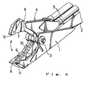
- a shear illustrated in Fig. 6 This shear comprises a lower jaw 1 rigidly mounted on the arm 2 of a power shovel and an upper jaw 4 connected to said lower jaw 1 through a pivot 3 so that the upper jaw may open and close with respect to the lower jaw.
- the steel reinforcement for instance, is trapped between said upper and lower jaws and the upper jaw 4 is then closed By means of an associated hydraulic cylinder 5 to shear the reinforcement.
- the upper and lower jaws are recessed away from each other in a longitudinally intermediate position to prevent forward displacement of the gripped load on shearing.
- the upper jaw 4 is formed as a single member and the lower jaw 1 as two parallel members so that the forward end of the upper jaw 4 may descend into the clearance between the two members of the lower jaw 1.
- These two parallel members of the lower jaw 1 are interconnected by a front end member 6.
- the mating edge portions of the upper and lower jaws 1,4 are respectively provided with plural cutting edges 7,8,9,10.
- wear plates 11,12 are rigidly secured to the upper and lower jaws, respectively, on the side opposite to said cutting edges 7,8,9,10 so that the upper jaw 4 will not be deflected sideways in shearing.
- the proposed shear has the problem that the cutting edge 7 of the upper jaw 4 and that 9 of the lower jaw 1 are parallel even in the maximum opening position of the jaws and do not open further so that the maximum degree of opening cannot be large.
- any shear designed to preclude a forward slip of the gripped load cannot have a large opening.
- the object of the present invention is to overcome the above disadvantages of the prior art.
- the present invention is directed to a reinforcing steel shear swingably mountable at the free end of a construction machine arm and including a stationary lower jaw having cutting edge means and a movable upper jaw having associated cutting edge means, with said upper jaw being recessed apart from said lower jaw in a longitudinally intermediate position, comprising a hydraulic cylinder disposed in a substantially vertical position and connected to said upper jaw at its rear end, said upper jaw being divided into a forward segment and a rear segment which are interconnected by bolt means selectively installed in one or another set of bolt holes provided in a plurality of rows whose imaginary downward extensions intersect each other.
- the steel shear of the invention weighs about 3800 kg and has a cutting edge length of about 800 mm.
- This steel sheer shown in Figs. 1 through 4, is characterized in that the maximum opening of its jaws can be selectively set to two degrees, viz. about 600 mm and about 390 mm.
- This steel shear has a lower jaw 1 extending integrally from a shear body 13 and an upper jaw 4 which is swingably connected to said lower jaw through a pivotal shaft 3 in such a manner that the upper jaw 4 may swing vertically to open and close with respect to said lower jaw 1.
- the upper jaw 4 and lower jaw 1 are recessed apart in an intermediate longitudinal position so that the gripped load will not slide longitudinally forward on gripping and shearing.
- the upper surface of the lower jaw 1 is formed with a land 1a configured in the shape of the numeral "7" and two cutting edges 9 and 10 are mounted on the shank portion of this 7-shaped land as shown in Figs. 1 and 2. Furthermore, the forward end of the lower jaw 1 is provided with a through-opening 14 for accepting the overlying forward end of the upper jaw 4.
- the bottom of said shear body 13 is provided with cylinder bosses 15 by which the free end of a piston rod 16 of a hydraulic cylinder 5a is rotatably supported.
- This hydraulic cylinder 5a is disposed in a substantially vertical position within the shear body 13 and connected to the rear end of said upper jaw 4.
- the upper jaw 4 is caused to swing upward or downward to open or close with respect to the lower jaw 1.
- a bracket 18 is rigidly secured to the rear wall of the shear body 13 through a swing bearing 17.
- This bracket 18 is provided with an arm pin 19 for coupling with the arm of a power shovel (not shown) and a pin 20 to which the force of a booming hydraulic cylinder (which is installed in parallel with said arm) is transmitted for rotating the bracket 18.
- the swing bearing 17 mentioned above has a built-in internal gear (not shown) which is in mesh with the pinion of a built-in hydraulic motor (not shown), whereby the steel shear may be swung through 360° with respect to the power shovel arm.
- the maximum opening between cutting edges 7 and 9 may be selectively set to whichever of two degrees.
- the upper jaw 4 is divided into a forward upper jaw segment 21 and a rear upper jaw segment 22 and a cutting edge is mounted on each of said forward and rear upper jaw segments 21,22.
- the upper jaw 4 is split into two parts along the junction between the cutting edges 7 and 8.
- the rear part of the forward upper jaw segment 21 constitutes a fork 21a, while the forward part of the rear upper jaw segment 22 is formed with a tongue or projection 22a configured to fit into said fork 21a.
- the fork 21a has a pair of bolt holes 23,23 formed in a vertical row, while the projection 22a is provided with two pairs of bolt holes 24,24 and 25,25 disposed in a first row 24a and a second row 25a, respectively. These pairs of bolt holes 23,23,24,24 and 25,25 are respectively disposed at the same pitch so that the fork 21a and projection 22a may be rigidly connected to each other by means of a couple of bolts 26.
- the first row 24a of bolt holes 24,24 is inclined forward with respect to the second row 25a of bolt holes 25,25 so that the downward imaginary extension of said first row 24a and that of said row 25a intersect with each other.
- the forward end of the upper jaw 4 may open with respect to the lower jaw 1 to the maximum degree of opening L 1 as shown in Fig. 3.
- the forward end of the upper jaw 4 may open with respect to the lower jaw 1 to the maximum degree of opening L 2 as shown in Fig. 4.
- the relationship of said maximum degrees of opening is L 1 > L 2 .
- the shear of the invention when it is set to the maximum degree of opening L 1 as shown in Fig. 3, it can be used to shear the reinforcing steel of a reinforced concrete building.
- the shear when it is set to the maximum opening L 2 as shown in Fig. 4, the shear can be used to grip and shear the steel member lain on the ground, for instance.
- the forward upper jaw segment 21 is connected to the rear upper jaw segment 22 in a stepped arrangement 27, instead of the fork-and-tongue arrangement described for the first embodiment.
- the arrangement of bolt holes is the same as in the first embodiment.
- the steel shear of the present invention can be used not only in the demolition of buildings but also in the demolition of chemical plant pipelines, automobiles and so on.
- the hydraulic cylinder for driving the upper jaw is disposed in a substantially vertical position, the shear as a whole can be provided in a compact form. Moreover, since this shear is swingable, shearing can be performed in the optimum position. Installation of a hydraulic cylinder in a vertical position would limit the maximum opening of the upper jaw. However, since the upper jaw is divided into two segments which can be connected by bolts in a choice of positions in the present invention, the shear of the invention provides for a sufficiently large opening of the jaws. Moreover, the jaw opening is adjustable to cope with varying sizes of shearing loads.
Landscapes
- Engineering & Computer Science (AREA)
- Mechanical Engineering (AREA)
- Working Measures On Existing Buildindgs (AREA)
Description
- The present invention relates to a heavy duty shear for use in the demolition of buildings and other applications.
- Generally, in the demolition of reinforced concrete buildings, a reinforcement shear mounted at the free end of the arm of a power shovel is employed. As an example of such shear, there is known a shear comprising a stationary lower jaw having a cutting edge and a movable upper jaw having an associated cutting edge and adapted to open and close with respect to said stationary lower jaw, said cutting edges being respectively straight edges (cf. Japanese Utility Model Application Kokai S-54-167871).
- This type of shear having straight cutting edges as mentioned above can shear iron sheet and the like neatly but cannot shear reinforcing steel or the like because such a shearing load tends to slip forward unless fixed somehow in position.
- To solve this problem, United States Patent 4,519,135 representing the closest prior art proposes a shear illustrated in Fig. 6. This shear comprises a
lower jaw 1 rigidly mounted on thearm 2 of a power shovel and anupper jaw 4 connected to saidlower jaw 1 through apivot 3 so that the upper jaw may open and close with respect to the lower jaw. In use of the shear, the steel reinforcement, for instance, is trapped between said upper and lower jaws and theupper jaw 4 is then closed By means of an associatedhydraulic cylinder 5 to shear the reinforcement. In this shear, the upper and lower jaws are recessed away from each other in a longitudinally intermediate position to prevent forward displacement of the gripped load on shearing. - In addition, the
upper jaw 4 is formed as a single member and thelower jaw 1 as two parallel members so that the forward end of theupper jaw 4 may descend into the clearance between the two members of thelower jaw 1. These two parallel members of thelower jaw 1 are interconnected by afront end member 6. The mating edge portions of the upper andlower jaws plural cutting edges wear plates cutting edges upper jaw 4 will not be deflected sideways in shearing. - However, the proposed shear has the problem that the
cutting edge 7 of theupper jaw 4 and that 9 of thelower jaw 1 are parallel even in the maximum opening position of the jaws and do not open further so that the maximum degree of opening cannot be large. In other words, generally any shear designed to preclude a forward slip of the gripped load cannot have a large opening. - The object of the present invention is to overcome the above disadvantages of the prior art.
- The present invention is directed to a reinforcing steel shear swingably mountable at the free end of a construction machine arm and including a stationary lower jaw having cutting edge means and a movable upper jaw having associated cutting edge means, with said upper jaw being recessed apart from said lower jaw in a longitudinally intermediate position, comprising a hydraulic cylinder disposed in a substantially vertical position and connected to said upper jaw at its rear end, said upper jaw being divided into a forward segment and a rear segment which are interconnected by bolt means selectively installed in one or another set of bolt holes provided in a plurality of rows whose imaginary downward extensions intersect each other.
- The present invention is now described in further detail with reference to the accompanying drawings which illustrate the preferred embodiments.
-
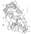
- Fig. 1 is a perspective view showing a first embodiment of the present invention;
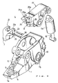
- Fig. 2 is a disassembled perspective view of the embodiment of Fig. 2;
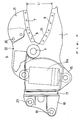
- Fig. 3 is a side elevation view of the same embodiment with its jaws set to a larger maximum opening.
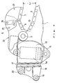
- Fig. 4 is a similar side elevation view of the same embodiment with its jaws set to a smaller maximum opening;
- Fig. 5 is a perspective view showing a second embodiment of the invention; and
- Fig. 6 is a perspective view showing the prior art shear.
- The steel shear of the invention weighs about 3800 kg and has a cutting edge length of about 800 mm. This steel sheer, shown in Figs. 1 through 4, is characterized in that the maximum opening of its jaws can be selectively set to two degrees, viz. about 600 mm and about 390 mm.
- This steel shear has a
lower jaw 1 extending integrally from ashear body 13 and anupper jaw 4 which is swingably connected to said lower jaw through apivotal shaft 3 in such a manner that theupper jaw 4 may swing vertically to open and close with respect to saidlower jaw 1. When a shearing load is trapped between theupper jaw 4 andlower jaw 1 in the above arrangement and theupper jaw 1 is closed by means of an associatedhydraulic cylinder 5a, the load trapped between the jaws is firmly gripped and shorn. - The
upper jaw 4 andlower jaw 1 are recessed apart in an intermediate longitudinal position so that the gripped load will not slide longitudinally forward on gripping and shearing. - The upper surface of the
lower jaw 1 is formed with aland 1a configured in the shape of the numeral "7" and twocutting edges lower jaw 1 is provided with a through-opening 14 for accepting the overlying forward end of theupper jaw 4. - The bottom of said
shear body 13 is provided withcylinder bosses 15 by which the free end of apiston rod 16 of ahydraulic cylinder 5a is rotatably supported. Thishydraulic cylinder 5a is disposed in a substantially vertical position within theshear body 13 and connected to the rear end of saidupper jaw 4. Thus, as thehydraulic cylinder 5a is operated, theupper jaw 4 is caused to swing upward or downward to open or close with respect to thelower jaw 1. - A
bracket 18 is rigidly secured to the rear wall of theshear body 13 through a swing bearing 17. Thisbracket 18 is provided with anarm pin 19 for coupling with the arm of a power shovel (not shown) and apin 20 to which the force of a booming hydraulic cylinder (which is installed in parallel with said arm) is transmitted for rotating thebracket 18. - The swing bearing 17 mentioned above has a built-in internal gear (not shown) which is in mesh with the pinion of a built-in hydraulic motor (not shown), whereby the steel shear may be swung through 360° with respect to the power shovel arm.
- In this embodiment of the invention, the maximum opening between
cutting edges upper jaw 4 is divided into a forwardupper jaw segment 21 and a rearupper jaw segment 22 and a cutting edge is mounted on each of said forward and rearupper jaw segments upper jaw 4 is split into two parts along the junction between thecutting edges - The rear part of the forward
upper jaw segment 21 constitutes afork 21a, while the forward part of the rearupper jaw segment 22 is formed with a tongue orprojection 22a configured to fit intosaid fork 21a. - The
fork 21a has a pair ofbolt holes projection 22a is provided with two pairs ofbolt holes second row 25a, respectively. These pairs ofbolt holes fork 21a andprojection 22a may be rigidly connected to each other by means of a couple ofbolts 26. - As illustrated, the first row 24a of
bolt holes second row 25a ofbolt holes row 25a intersect with each other. In this arrangement, as thebolts holes second row 25a are lined up with thebolt holes 23 of thefork 21a and threaded tight, the forward end of theupper jaw 4 may open with respect to thelower jaw 1 to the maximum degree of opening L1 as shown in Fig. 3. - On the other hand, as the
bolts holes bolt holes fork 21a and threaded tight, the forward end of theupper jaw 4 may open with respect to thelower jaw 1 to the maximum degree of opening L2 as shown in Fig. 4. The relationship of said maximum degrees of opening is L1 > L2. - Thus, when the shear of the invention is set to the maximum degree of opening L1 as shown in Fig. 3, it can be used to shear the reinforcing steel of a reinforced concrete building. On the other hand, when it is set to the maximum opening L2 as shown in Fig. 4, the shear can be used to grip and shear the steel member lain on the ground, for instance.
- It should be understood that while said
projection 22a was described above as having bolt holes in tworows 24a,25a, it may be provided with bolt holes in 3 or 4 rows. - A second embodiment of the present invention is now described with reference to Fig. 5. The parts corresponding to those of the first embodiment are not described and only the difference from the first embodiment is described below.
- As shown in Fig. 5, the forward
upper jaw segment 21 is connected to the rearupper jaw segment 22 in astepped arrangement 27, instead of the fork-and-tongue arrangement described for the first embodiment. The arrangement of bolt holes is the same as in the first embodiment. By this arrangement, too, the object of the invention can be effectively accomplished. - The steel shear of the present invention can be used not only in the demolition of buildings but also in the demolition of chemical plant pipelines, automobiles and so on.
- Since, in the present invention, the hydraulic cylinder for driving the upper jaw is disposed in a substantially vertical position, the shear as a whole can be provided in a compact form. Moreover, since this shear is swingable, shearing can be performed in the optimum position. Installation of a hydraulic cylinder in a vertical position would limit the maximum opening of the upper jaw. However, since the upper jaw is divided into two segments which can be connected by bolts in a choice of positions in the present invention, the shear of the invention provides for a sufficiently large opening of the jaws. Moreover, the jaw opening is adjustable to cope with varying sizes of shearing loads.
Claims (1)
- A reinforcing steel shear swingably mountable at the free end of a construction machine arm and including a stationary lower jaw (1) having cutting edge means (9,10) and a movable upper jaw (4) having associated cutting edge means (7,8), with said upper jaw being recessed apart from said lower jaw in a longitudinally intermediate position, comprising a hydraulic cylinder (5a) disposed in a substantially vertical position and connected to said upper jaw (4) at its rear end, said upper jaw (4) being divided into a forward segment (21) and a rear segment (22) which are interconnected by bolt means (26) selectively installed in one or another set of bolt holes (23,24,25) provided in a plurality of rows (24a,25a) whose imaginary downward extensions intersect each other.
Applications Claiming Priority (2)
| Application Number | Priority Date | Filing Date | Title |
|---|---|---|---|
| JP1992078087U JPH075161Y2 (en) | 1992-10-14 | 1992-10-14 | Steel cutting machine |
| JP78087/92 | 1992-10-14 |
Publications (2)
| Publication Number | Publication Date |
|---|---|
| EP0596285A1 EP0596285A1 (en) | 1994-05-11 |
| EP0596285B1 true EP0596285B1 (en) | 1997-07-16 |
Family
ID=13652070
Family Applications (1)
| Application Number | Title | Priority Date | Filing Date |
|---|---|---|---|
| EP93116558A Expired - Lifetime EP0596285B1 (en) | 1992-10-14 | 1993-10-13 | Reinforced steel shear |
Country Status (4)
| Country | Link |
|---|---|
| US (1) | US5339525A (en) |
| EP (1) | EP0596285B1 (en) |
| JP (1) | JPH075161Y2 (en) |
| DE (1) | DE69312219T2 (en) |
Families Citing this family (27)
| Publication number | Priority date | Publication date | Assignee | Title |
|---|---|---|---|---|
| JP3058247B2 (en) * | 1995-08-24 | 2000-07-04 | 大淀ヂ−ゼル株式会社 | Sickle type shearing machine |
| US5894666A (en) * | 1997-03-17 | 1999-04-20 | Npk Research, Inc. | Cutting and piercing tips for a metal cutting shear |
| US6926217B1 (en) | 1998-11-25 | 2005-08-09 | Genesis Attachments, Llc | Heavy-duty demolition apparatus with replaceable tip and rotatable cross blade |
| US6061911A (en) * | 1998-11-25 | 2000-05-16 | Genesis Equipment And Manufacturing Co. | Heavy-duty demolition apparatus with blade stabilizing device |
| US6119970A (en) * | 1998-11-25 | 2000-09-19 | Genesis Equipment & Manufacturing, Inc. | Heavy-duty demolition apparatus with replaceable crushing and shearing tip |
| JP3425138B2 (en) * | 2001-06-29 | 2003-07-07 | 株式会社坂戸工作所 | Industrial waste cutting device and its cutting method |
| JP3468758B2 (en) * | 2001-06-29 | 2003-11-17 | 株式会社坂戸工作所 | Industrial waste cutting device and its cutting method |
| US6839969B2 (en) | 2002-11-18 | 2005-01-11 | Genesis Equipment And Manufacturing, Inc. | Replaceable demolition shear piercing tip |
| US8146256B2 (en) * | 2003-10-31 | 2012-04-03 | Stanley Black & Decker, Inc. | Metal demolition shears with indexable, integrated wear plate/piercing tip |
| US7216575B2 (en) * | 2004-03-29 | 2007-05-15 | Genesis Attachments, Llc | Heavy-duty demolition apparatus with blade stabilizing puck |
| US7044037B2 (en) * | 2004-04-21 | 2006-05-16 | John R. Ramun | Tip for demolition and construction equipment |
| US7284718B2 (en) * | 2005-06-29 | 2007-10-23 | Genesis Attachments, Llc | Excavator demolition attachment with interchangeable jaw assemblies |
| US20070130776A1 (en) * | 2005-12-12 | 2007-06-14 | Patrick Grant | Shear with replaceable shearing tip |
| US20070145171A1 (en) * | 2005-12-23 | 2007-06-28 | The Stanley Works | Rebar cutting shears |
| AU2007300454A1 (en) * | 2006-09-27 | 2008-04-03 | Caterpillar Inc. | Reversible bolt-on piercing tip |
| JP5233840B2 (en) * | 2009-05-20 | 2013-07-10 | コベルコ建機株式会社 | Work machine gripping device and work machine equipped with the same |
| US9132490B2 (en) | 2012-06-11 | 2015-09-15 | John R. Ramun | Interlocking tip for demolition and construction equipment |
| NZ713052A (en) * | 2013-04-09 | 2018-06-29 | Genesis Attachments Llc | Demolition shear and demolition shear piercing tip insert and nose configuration |
| US10286461B2 (en) | 2014-04-25 | 2019-05-14 | Exodus Machines Incorporated | Adjustable shimable indexable shear tip |
| US10092967B2 (en) | 2014-04-25 | 2018-10-09 | Exodus Machines, Inc. | Three-sided shimable indexable shear tip boot |
| US10071431B2 (en) | 2014-04-25 | 2018-09-11 | Exodus Machines Incorporated | Four-sided shimable indexable shear tip boot |
| US9713848B2 (en) * | 2014-04-25 | 2017-07-25 | Exodus Machines, Inc. | Demolition shear tip boot |
| US20150308076A1 (en) * | 2014-04-25 | 2015-10-29 | Exodus Machines, Inc. | Demolition adjustable shimable shear tip |
| EP3121340B1 (en) * | 2015-07-20 | 2020-05-20 | Caterpillar Work Tools B. V. | Replaceable tip for a demolition tool |
| DE102017211870A1 (en) | 2017-07-11 | 2019-01-17 | Gebrüder Egli Maschinen Ag | Hydraulically operated pliers |
| JP6353619B1 (en) | 2018-02-27 | 2018-07-04 | 可明 高倉 | Large aircraft dismantling shears and large aircraft dismantling work vehicles |
| JP7216693B2 (en) * | 2020-10-30 | 2023-02-01 | ジェネシス アタッチメンツ,エルエルシー | Scissors for demolition and the structure of the insertion body and the tip of the piercing tip of the shears for demolition |
Family Cites Families (5)
| Publication number | Priority date | Publication date | Assignee | Title |
|---|---|---|---|---|
| US4198747A (en) * | 1978-11-22 | 1980-04-22 | Labounty Roy E | Hydraulic shear |
| JPH0710451B2 (en) * | 1986-11-25 | 1995-02-08 | 三五重機株式会社 | Steel sheet cutter |
| US4776093A (en) * | 1987-04-16 | 1988-10-11 | Aaa Steel And Enterprises Corporation | Metal demolition shears |
| JPH079970Y2 (en) * | 1991-05-20 | 1995-03-08 | 大淀小松株式会社 | Steel cutting machine |
| US5187868A (en) * | 1992-06-16 | 1993-02-23 | Hall Charlie R | Metal demolition shear |
-
1992
- 1992-10-14 JP JP1992078087U patent/JPH075161Y2/en not_active Expired - Lifetime
-
1993
- 1993-05-17 US US08/061,520 patent/US5339525A/en not_active Expired - Fee Related
- 1993-10-13 DE DE69312219T patent/DE69312219T2/en not_active Expired - Fee Related
- 1993-10-13 EP EP93116558A patent/EP0596285B1/en not_active Expired - Lifetime
Also Published As
| Publication number | Publication date |
|---|---|
| DE69312219D1 (en) | 1997-08-21 |
| US5339525A (en) | 1994-08-23 |
| DE69312219T2 (en) | 1998-02-26 |
| JPH0635524U (en) | 1994-05-13 |
| EP0596285A1 (en) | 1994-05-11 |
| JPH075161Y2 (en) | 1995-02-08 |
Similar Documents
| Publication | Publication Date | Title |
|---|---|---|
| EP0596285B1 (en) | Reinforced steel shear | |
| US5146683A (en) | Reinforcement cutter | |
| US5179794A (en) | Semi-automatic coupling apparatus | |
| US8245964B2 (en) | Dual moving jaws for demolition equipment | |
| EP0582746A1 (en) | Concrete breaker | |
| KR0136104B1 (en) | Articulated crane type machine with quick disconnect means | |
| AU693692B2 (en) | Shear processor for steel structures | |
| US5471747A (en) | Steel material shearing machine | |
| JPH0248708B2 (en) | ||
| US20060131454A1 (en) | Single jaw set multiple tool attachment system | |
| US7004712B2 (en) | Tool for exchangeably fastening an implement to an excavator boom | |
| EP0137693B1 (en) | Steel frame shearing apparatus | |
| US10414633B1 (en) | Grappling assembly for use with utility equipment | |
| US20090145274A1 (en) | Demolition shears | |
| EP1844199A1 (en) | Quick coupling device for a work tool | |
| US5291657A (en) | Shearing machine for steel material | |
| US5375329A (en) | Heavy duty shear | |
| US12534869B2 (en) | Construction machine | |
| CN213805531U (en) | Double-lock quick-change connector | |
| CN214933881U (en) | Reinforced claw adopting hydraulic rotary motor | |
| EP1240818A1 (en) | Cutting clamp for silage | |
| JPH0426592Y2 (en) | ||
| CA2089020A1 (en) | Scoop for a mobile implement | |
| KR200145736Y1 (en) | Grab for excavator attachment | |
| US12227917B2 (en) | Yoke assembly for excavator thumb |
Legal Events
| Date | Code | Title | Description |
|---|---|---|---|
| PUAI | Public reference made under article 153(3) epc to a published international application that has entered the european phase |
Free format text: ORIGINAL CODE: 0009012 |
|
| AK | Designated contracting states |
Kind code of ref document: A1 Designated state(s): DE FR GB IT NL |
|
| 17P | Request for examination filed |
Effective date: 19940524 |
|
| GRAG | Despatch of communication of intention to grant |
Free format text: ORIGINAL CODE: EPIDOS AGRA |
|
| 17Q | First examination report despatched |
Effective date: 19961112 |
|
| GRAH | Despatch of communication of intention to grant a patent |
Free format text: ORIGINAL CODE: EPIDOS IGRA |
|
| GRAH | Despatch of communication of intention to grant a patent |
Free format text: ORIGINAL CODE: EPIDOS IGRA |
|
| GRAA | (expected) grant |
Free format text: ORIGINAL CODE: 0009210 |
|
| AK | Designated contracting states |
Kind code of ref document: B1 Designated state(s): DE FR GB IT NL |
|
| PG25 | Lapsed in a contracting state [announced via postgrant information from national office to epo] |
Ref country code: FR Free format text: THE PATENT HAS BEEN ANNULLED BY A DECISION OF A NATIONAL AUTHORITY Effective date: 19970716 |
|
| REF | Corresponds to: |
Ref document number: 69312219 Country of ref document: DE Date of ref document: 19970821 |
|
| PG25 | Lapsed in a contracting state [announced via postgrant information from national office to epo] |
Ref country code: GB Free format text: LAPSE BECAUSE OF NON-PAYMENT OF DUE FEES Effective date: 19971016 |
|
| ET | Fr: translation filed | ||
| PG25 | Lapsed in a contracting state [announced via postgrant information from national office to epo] |
Ref country code: NL Free format text: LAPSE BECAUSE OF NON-PAYMENT OF DUE FEES Effective date: 19980501 |
|
| PLBE | No opposition filed within time limit |
Free format text: ORIGINAL CODE: 0009261 |
|
| STAA | Information on the status of an ep patent application or granted ep patent |
Free format text: STATUS: NO OPPOSITION FILED WITHIN TIME LIMIT |
|
| GBPC | Gb: european patent ceased through non-payment of renewal fee |
Effective date: 19971016 |
|
| NLV4 | Nl: lapsed or anulled due to non-payment of the annual fee |
Effective date: 19980501 |
|
| PG25 | Lapsed in a contracting state [announced via postgrant information from national office to epo] |
Ref country code: DE Free format text: LAPSE BECAUSE OF NON-PAYMENT OF DUE FEES Effective date: 19980701 |
|
| 26N | No opposition filed | ||
| REG | Reference to a national code |
Ref country code: FR Ref legal event code: ST |
|
| PG25 | Lapsed in a contracting state [announced via postgrant information from national office to epo] |
Ref country code: IT Free format text: LAPSE BECAUSE OF NON-PAYMENT OF DUE FEES Effective date: 20051013 |