EP0596167B1 - Variable ratio steering system for a motor vehicle - Google Patents
Variable ratio steering system for a motor vehicle Download PDFInfo
- Publication number
- EP0596167B1 EP0596167B1 EP92310135A EP92310135A EP0596167B1 EP 0596167 B1 EP0596167 B1 EP 0596167B1 EP 92310135 A EP92310135 A EP 92310135A EP 92310135 A EP92310135 A EP 92310135A EP 0596167 B1 EP0596167 B1 EP 0596167B1
- Authority
- EP
- European Patent Office
- Prior art keywords
- steer
- ratio
- signal
- steering
- velocity
- Prior art date
- Legal status (The legal status is an assumption and is not a legal conclusion. Google has not performed a legal analysis and makes no representation as to the accuracy of the status listed.)
- Expired - Lifetime
Links
Images



Classifications
-
- B—PERFORMING OPERATIONS; TRANSPORTING
- B62—LAND VEHICLES FOR TRAVELLING OTHERWISE THAN ON RAILS
- B62D—MOTOR VEHICLES; TRAILERS
- B62D5/00—Power-assisted or power-driven steering
- B62D5/04—Power-assisted or power-driven steering electrical, e.g. using an electric servo-motor connected to, or forming part of, the steering gear
- B62D5/0418—Electric motor acting on road wheel carriers
-
- B—PERFORMING OPERATIONS; TRANSPORTING
- B62—LAND VEHICLES FOR TRAVELLING OTHERWISE THAN ON RAILS
- B62D—MOTOR VEHICLES; TRAILERS
- B62D6/00—Arrangements for automatically controlling steering depending on driving conditions sensed and responded to, e.g. control circuits
- B62D6/002—Arrangements for automatically controlling steering depending on driving conditions sensed and responded to, e.g. control circuits computing target steering angles for front or rear wheels
-
- B—PERFORMING OPERATIONS; TRANSPORTING
- B62—LAND VEHICLES FOR TRAVELLING OTHERWISE THAN ON RAILS
- B62D—MOTOR VEHICLES; TRAILERS
- B62D6/00—Arrangements for automatically controlling steering depending on driving conditions sensed and responded to, e.g. control circuits
- B62D6/02—Arrangements for automatically controlling steering depending on driving conditions sensed and responded to, e.g. control circuits responsive only to vehicle speed
Definitions
- the invention refers to a variable steering ratio feedback control circuit for a material handling vehicle according to the preamble of claim 1.
- US-A-5 128 598 teaches a unique steer/drive control system for steering a material handling vehicle by the use of directly coupled traction and steering motors.
- the steering motor is fabricated as a hollow shaft dc motor, whose inner ring represents the rotor, and whose outer ring represents the stator.
- the stator is connnected to a frame of the vehicle carrying the steering and drive wheel.
- the rotor is integrally connected to the traction motor that drives the steering and drive wheel.
- a hand operated steering mechanism rotationally guides the vehicle.
- a steering angle sensor determines the difference between actual and desired heading of the steering and drive wheel.
- the steer/drive system utilizes the sensed difference, and generates a signal for controlling the heading of the steering and drive wheel.
- the invention is related to a system for changing the steering ratio of a steerable vehicle as a function of its speed, and more particularly to a microprocessor-based, electronic system that changes the lock-to-lock turns of the steering wheel or column, as the speed of a motorized vehicle increases.
- the present invention relates to a steering system for a motorized vehicle with particular emphasis on an electronic steering control for a material handling vehicle, such as fork lift truck.
- One of the best ways to influence the steering sensitivity is to change the steering ratio (i.e., the number of turns from lock-to-lock of the steering wheel or column).
- An electronic steering control system has greater flexibility than a mechanical control system, and is lower in cost.
- a mechanical control may require replacing or adjusting mechanical gearing, while an electronic system using a microprocessor-based control can be easily modified by changing programming parameters.
- Electronic steering control is particularly useful for material handling vehicles, such as fork lift trucks. Such vehicles generally have integrally functioning drive and steering motors. Where the drive and steering functions are united in a common control system, a microprocessor control is an extremely flexible means of providing adjustments and control modifications.
- the present invention differs from the above patent in that the modification to the steering control is based solely on the vehicular speed, which speed is used to modify the steering ratio (i.e., turns of the steering wheel from lock-to-lock), rather than the torque upon the steering wheel.
- an electronic feedback circuit under microprocessor control for varying the steering ratio of a motorized material handling vehicle in response to the vehicular speed.
- the lock-to-lock turn of the steering wheel or column is electronically adjusted in order to modify the steering response (i.e., steering angle) of the steer/drive wheel with respect to an increase in speed of the vehicle.
- the microprocessor controlled system comprises a vehicle velocity sensor that sends a signal of vehicular speed to a steer ratio filter.
- the steer ratio filter supplies an incremental change in the steering ratio for controlling the steer/drive wheel in response to the change sensed in the vehicular velocity.
- Such a change may be a straight-line function, in which case the steer ratio will change directly in proportion to an increase in the vehicular speed.
- the incremental change signal from the steer ratio filter is summed with a steer position reference signal provided from the steer/drive wheel of the vehicle.
- the summed signal is then fed to a position filter that provides a steer/drive wheel position signal.
- a position controller operatively connected to the gear reduction of the steer/drive wheel provides a feedback position signal of the gear reduction position, which is summed with the signal from the position filter.
- the new position signal is then fed to a motor velocity filter that provides a steer motor velocity signal to control the steering angle of the steer/drive motor.
- the motor velocity signal is summed with a motor velocity feedback signal provided by a velocity controller operatively connected to the steer motor.
- the summed motor velocity signals are then amplified and fed to the steer motor to change its steer ratio response as a function of the motor vehicle speed. In other words, a greater turn of the steering wheel will be required to effect an angle change in the steer/drive wheel as the speed of the material handling vehicle increases.
- the present invention features a new variable ratio steering system for the control of a motor vehicle, such as a material handling vehicle.
- a motor vehicle such as a material handling vehicle.
- a conventional lift truck steering and drive system is shown generally at reference numeral 20.
- the steering and drive system 20 features a spaced-apart steer motor 21 and traction motor 12.
- the material handling truck has a single, combination steering and drive wheel 17 that is driven by the traction motor 12 via an internal drive shaft (not shown).
- the internal drive shaft engages the steering and drive unit 16, which comprises a transmission that adapts the speed of the wheel 17 to that of the traction motor 12.
- the traction motor 12 and steering and drive unit 16 are attached and integrally mounted on the material handling truck frame 15.
- a pinion gear 23 driven by the steer motor 21 through a gear reducer 22 drives a master gear 25 attached to the traction motor 12 via a drive chain 27.
- a steer motor speed sensor 29 is mounted upon the steer motor 21, which can be either an electric or a hydraulic motor. Steer motor speed sensor 29 detects the speed of steer motor 21.
- a steer position sensor 10 and a travel speed sensor 11 are mounted upon the traction motor 12, as shown. Travel speed sensor 11 detects the speed of traction motor 12 on which it is mounted, while steer position sensor 10 detects drive unit steering position.
- the power control circuit includes a transistorized, H-bridge armature voltage amplifier circuit 40 connected across the armature 13 of the steering motor 21.
- the H-bridge armature voltage amplifier circuit 40 determines the direction of dc motor rotation, and applies voltage to the armature. This power control circuit is under the influence of a microprocessor, not shown.
- a circuit for varying the steering ratio "R” as a function of the vehicle speed “V” is shown generally at reference numeral 100.
- the circuit 100 obtains a vehicle velocity reading from a velocity sensor (not shown), whose vehicle velocity signal 101 is fed to a steer ratio filter 102.
- the steer ratio filter 102 provides an incremental R signal 103 of changed steer ratio that is summed with a steer/drive wheel position reference signal 104 obtained from a steer/drive wheel sensor (not shown).
- system can also be adapted to operate as a velocity controller, rather than as a position controller, where the control system responds to a rate change of the input signal.
- position signals are described exclusively hereinafter.
- the summed position signal 105 is fed to steer position filter 106.
- the steer position filter 106 provides a signal 107 in response to the new position calculated for the steer/drive wheel 17 (FIGURE 2).
- Signal 107 is then summed with a feedback signal 108, generated by drive unit position decoder 110, to which is applied the signal 119 from position feedback sensor 10 (FIGURE 2).
- the resultant position signal 109 is then fed to a drive unit controller 111, as shown, which generates a signal 112 that is summed with the feedback signal 113 generated by steer motor position decoder 114, to which is applied the signal 118 from steer sensor 29 (FIGURE 2).
- the resultant position signal 115 is then fed to a steer motor controller 116, which generates a signal 117 that is amplified and which controls the rotation of steer motor 21 via the driving circuit illustrated in FIGURE 3.
- R c for V ⁇ a
- R d - c b - a .
- R d for V > b
- the steering ratio "R” varies in accordance with a straight-line function, between a minimum threshold speed "a”, and a maximum threshold speed "b". These formulas are derived from the graph shown in FIGURE 5. For vehicular speeds less than “a”, the steering ratio will remain “c”; and for speeds greater than “b”, the steering ratio will remain “d”, as illustrated. Variables "a” through “d” and “V” may vary depending on the application.
Landscapes
- Engineering & Computer Science (AREA)
- Chemical & Material Sciences (AREA)
- Combustion & Propulsion (AREA)
- Transportation (AREA)
- Mechanical Engineering (AREA)
- Physics & Mathematics (AREA)
- Mathematical Physics (AREA)
- Steering Control In Accordance With Driving Conditions (AREA)
Description
- The invention refers to a variable steering ratio feedback control circuit for a material handling vehicle according to the preamble of
claim 1. - US-A-5 128 598 teaches a unique steer/drive control system for steering a material handling vehicle by the use of directly coupled traction and steering motors. The steering motor is fabricated as a hollow shaft dc motor, whose inner ring represents the rotor, and whose outer ring represents the stator. The stator is connnected to a frame of the vehicle carrying the steering and drive wheel. The rotor is integrally connected to the traction motor that drives the steering and drive wheel. A hand operated steering mechanism rotationally guides the vehicle. A steering angle sensor determines the difference between actual and desired heading of the steering and drive wheel. The steer/drive system utilizes the sensed difference, and generates a signal for controlling the heading of the steering and drive wheel.
- The invention is related to a system for changing the steering ratio of a steerable vehicle as a function of its speed, and more particularly to a microprocessor-based, electronic system that changes the lock-to-lock turns of the steering wheel or column, as the speed of a motorized vehicle increases.
- The present invention relates to a steering system for a motorized vehicle with particular emphasis on an electronic steering control for a material handling vehicle, such as fork lift truck.
- It is an object of the invention to increase the sensitivity of the steering of a motorized vehicle at low vehicular speeds in order to provide better maneuverability and parking control. At higher speeds the steering sensitivity should be decreased, since large displacements can result from small corrections. One of the best ways to influence the steering sensitivity is to change the steering ratio (i.e., the number of turns from lock-to-lock of the steering wheel or column).
- It is a further object to modify the steering sensitivity utilizing electronic rather than mechanical controls. An electronic steering control system has greater flexibility than a mechanical control system, and is lower in cost. For example, a mechanical control may require replacing or adjusting mechanical gearing, while an electronic system using a microprocessor-based control can be easily modified by changing programming parameters.
- Electronic steering control is particularly useful for material handling vehicles, such as fork lift trucks. Such vehicles generally have integrally functioning drive and steering motors. Where the drive and steering functions are united in a common control system, a microprocessor control is an extremely flexible means of providing adjustments and control modifications.
- According to the present invention, the objects are achieved by the control circuit defined in
independent claims - In United States Patent No. 4,940,102, issued to Morishita on July 10, 1990, for "Motor-Driven Power Steering System," a DC motor provides an auxiliary steering force to a steering system based upon a steering torque signal and a vehicle speed signal. The rotational force necessary to control the steering of the vehicle is modified by a clutch mechanism that turns the DC motor on and off in response to the received signals.
- The present invention differs from the above patent in that the modification to the steering control is based solely on the vehicular speed, which speed is used to modify the steering ratio (i.e., turns of the steering wheel from lock-to-lock), rather than the torque upon the steering wheel.
- In United States Patent No. 4,873,475, issued to Togo et al on October 10, 1989, for "Electrically Powered Power Steering System for Industrial Vehicle or the Like," an electronic control is illustrated for preventing a kickback felt through the steering wheel when the steering motor is de-energized. The de-energization of the motor produces a condition wherein there is no countering force upon the steering shaft to oppose the twisted tires of the vehicle, which then tend to relieve any residual forces in the rubber. The patent teaches a control for gradual reduction in the steering torque to prevent the sudden kickback force.
- In accordance with the present invention, there is provided an electronic feedback circuit under microprocessor control for varying the steering ratio of a motorized material handling vehicle in response to the vehicular speed. The lock-to-lock turn of the steering wheel or column is electronically adjusted in order to modify the steering response (i.e., steering angle) of the steer/drive wheel with respect to an increase in speed of the vehicle. The microprocessor controlled system comprises a vehicle velocity sensor that sends a signal of vehicular speed to a steer ratio filter. The steer ratio filter supplies an incremental change in the steering ratio for controlling the steer/drive wheel in response to the change sensed in the vehicular velocity. Such a change may be a straight-line function, in which case the steer ratio will change directly in proportion to an increase in the vehicular speed.
- The incremental change signal from the steer ratio filter is summed with a steer position reference signal provided from the steer/drive wheel of the vehicle. The summed signal is then fed to a position filter that provides a steer/drive wheel position signal. A position controller operatively connected to the gear reduction of the steer/drive wheel provides a feedback position signal of the gear reduction position, which is summed with the signal from the position filter. The new position signal is then fed to a motor velocity filter that provides a steer motor velocity signal to control the steering angle of the steer/drive motor. The motor velocity signal is summed with a motor velocity feedback signal provided by a velocity controller operatively connected to the steer motor. The summed motor velocity signals are then amplified and fed to the steer motor to change its steer ratio response as a function of the motor vehicle speed. In other words, a greater turn of the steering wheel will be required to effect an angle change in the steer/drive wheel as the speed of the material handling vehicle increases.
- In US-A-5 128 598 it is taught that the steering motor and drive motor for the steer/drive wheel can be combined or directly coupled together, to form a common steer/drive DC motor. In such a system, the aforementioned control circuitry does not require a motor velocity feedback signal, since the gear reducer is eliminated. Hence, the motor velocity controller and its associated feedback loop are eliminated for a system utilizing a coupled steer/drive DC motor.
- A complete understanding of the present invention may be obtained by reference to the accompanying drawings, when taken in conjunction with the detailed description thereof and in which:
- FIGURE 1 is a perspective view of a material handling vehicle incorporating the variable ratio steering system of the present invention;
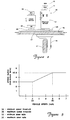
- FIGURE 2 is a schematic view, shown in sectional cross-cut, of a gear reducer, pinion gear, chain driven, steering and drive motor system for a material handling vehicle;
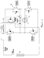
- FIGURE 3 is a diagrammatic view of the power control circuit for the variable ratio system of this invention;
- FIGURE 4a is a block diagram of a feedback control circuit for the variable ratio steering system of the invention;
- FIGURE 4b is a block diagram of a feedback control circuit for an integrally coupled steering and drive motor embodiment of the invention; and
- FIGURE 5 is a graphical representation of steer ratio as a function of vehicle speed.
- For purposes of brevity, like elements will bear the same designations throughout the figures.
- Generally speaking, the present invention features a new variable ratio steering system for the control of a motor vehicle, such as a material handling vehicle. As the speed of a material handling vehicle increases from a minimum speed threshold "a" to a maximum speed threshold "b", the steer ratio "R" of the steering control of the vehicle will be made to vary in accordance with the following straight-line function:

- V =
- velocity of the material handling vehicle
- c =
- a minimum steer ratio (turns lock-to-lock)
- d =
- a maximum steer ratio (turns lock-to lock)
- Referring now also to FIGURE 2, a conventional lift truck steering and drive system is shown generally at
reference numeral 20. The steering anddrive system 20 features a spaced-apartsteer motor 21 andtraction motor 12. - The material handling truck has a single, combination steering and drive
wheel 17 that is driven by thetraction motor 12 via an internal drive shaft (not shown). The internal drive shaft engages the steering and driveunit 16, which comprises a transmission that adapts the speed of thewheel 17 to that of thetraction motor 12. Thetraction motor 12 and steering and driveunit 16 are attached and integrally mounted on the material handlingtruck frame 15. - A
pinion gear 23 driven by thesteer motor 21 through agear reducer 22 drives amaster gear 25 attached to thetraction motor 12 via adrive chain 27. A steermotor speed sensor 29 is mounted upon thesteer motor 21, which can be either an electric or a hydraulic motor. Steermotor speed sensor 29 detects the speed ofsteer motor 21. - A
steer position sensor 10 and atravel speed sensor 11 are mounted upon thetraction motor 12, as shown.Travel speed sensor 11 detects the speed oftraction motor 12 on which it is mounted, whilesteer position sensor 10 detects drive unit steering position. - As an alternate embodiment of the steering/drive system, co-pending patent application serial no. 07/627,106, filed December 13, 1990 for "Material Handling Vehicle Steering System," hereby incorporated by reference, describes a steer motor that directly couples with, and rotationally drives the traction motor. This eliminates the
conventional pinion gear 23, thegear reducer 22, themaster gear 25 and thedrive chain 27, as well as the steermotor speed sensor 29, which is incorporated into thesteer position sensor 10 of thetraction motor 12. The function of the steermotor speed sensor 29 can thus be incorporated in thesteer position sensor 10. - With the elimination of the drive chain, gear reducer and pinion gear components, the aforementioned system eliminates the problem of harmonic oscillation attendant with drive chain backlash. This improved steering system can likewise be further improved by incorporation of the present invention, as will be further explained herein with reference to FIGURE 4b.
- Referring now also to FIGURE 3, the power control circuit includes a transistorized, H-bridge armature
voltage amplifier circuit 40 connected across thearmature 13 of thesteering motor 21. The H-bridge armaturevoltage amplifier circuit 40 determines the direction of dc motor rotation, and applies voltage to the armature. This power control circuit is under the influence of a microprocessor, not shown. - Referring to FIGURE 4a, a circuit for varying the steering ratio "R" as a function of the vehicle speed "V" is shown generally at
reference numeral 100. Thecircuit 100 obtains a vehicle velocity reading from a velocity sensor (not shown), whosevehicle velocity signal 101 is fed to asteer ratio filter 102. Thesteer ratio filter 102 provides an incremental R signal 103 of changed steer ratio that is summed with a steer/drive wheelposition reference signal 104 obtained from a steer/drive wheel sensor (not shown). - It should be understood that the system can also be adapted to operate as a velocity controller, rather than as a position controller, where the control system responds to a rate change of the input signal. For purposes of this description, however, position signals are described exclusively hereinafter.
- Once the summing operation occurs, the summed
position signal 105 is fed to steerposition filter 106. Thesteer position filter 106 provides asignal 107 in response to the new position calculated for the steer/drive wheel 17 (FIGURE 2).Signal 107 is then summed with afeedback signal 108, generated by driveunit position decoder 110, to which is applied thesignal 119 from position feedback sensor 10 (FIGURE 2). The resultant position signal 109 is then fed to adrive unit controller 111, as shown, which generates asignal 112 that is summed with thefeedback signal 113 generated by steermotor position decoder 114, to which is applied thesignal 118 from steer sensor 29 (FIGURE 2). The resultant position signal 115 is then fed to asteer motor controller 116, which generates asignal 117 that is amplified and which controls the rotation ofsteer motor 21 via the driving circuit illustrated in FIGURE 3. - In the embodiment of the directly driven steer/drive system illustrated and described in related application, Serial No. 07/627,106, the need for a
feedback signal 113, steermotor position decoder 114, and steermotor controller 116 is eliminated with the absence of thesteer gear reducer 16, as aforementioned, giving rise to thecircuit 100a, shown in FIGURE 4b. - The steering ratio "R" will vary as follows:

- V =
- velocity of the material handling vehicle
- a =
- minimum threshold speed
- b =
- maximum threshold speed
- c =
- minimum steer ratio (turns lock-to-lock)
- d =
- maximum steer ratio (turns lock-to-lock).
- In other words, the steering ratio "R" varies in accordance with a straight-line function, between a minimum threshold speed "a", and a maximum threshold speed "b". These formulas are derived from the graph shown in FIGURE 5. For vehicular speeds less than "a", the steering ratio will remain "c"; and for speeds greater than "b", the steering ratio will remain "d", as illustrated. Variables "a" through "d" and "V" may vary depending on the application.
- While the above invention has been designed with respect to a linear correction of the steering ratio with respect to the speed of the vehicle, a non-linear correction could have been easily provided, if it had been desired to do so.
Claims (11)
- A variable steering ratio feedback control circuit (100) for a material handling vehicle (1), comprising a steer motor (21) for steering a material handling vehicle (1) via a steer/drive wheel (17),
characterized by
a steer ratio filter (102) for generating a steer ratio signal (103) in response to a change in velocity of said vehicle (1),
first summing means operatively connected to said steer ratio filter (102) for summing a steering position reference signal (104) with said steer ratio signal (103) generated by said steer ratio filter (102) to provide a first summed signal (105),
a position filter (106) for receiving said first summed signal (105) and in response thereto, generating a steering position signal (107),
first feedback control means operatively connected to said steer motor (21) for providing a feedback position signal (108) with respect to said steer motor (21), second summing means operatively connected to said position filter (106) and said first feedback control means for summing said steering position signal (107) with said feedback position signal (108) to provide a second summed signal (109), and
a velocity filter operatively connected to said second summing means for generating a motor velocity signal to said steer motor (21) for steering said material handling vehicle (1) in response to said second summed signal (109). - The variable steering ratio feedback control circuit for a material handling vehicle in accordance with claim 1, further comprising:
second feedback control means disposed between said first feedback control means and said velocity filter for generating a second feedback control signal (113); and
third summing means operatively connected between said velocity filter and said second feedback control means for summing said second feedback control signal (113) with said motor velocity signal. - The variable steering ratio feedback control circuit for a material handling vehicle in accordance with claim 1, wherein said steer ratio filter (102) provides an incremental change in the steer ratio signal (103) in response to a change in velocity of said material handling vehicle (1).
- The variable steering ratio feedback control circuit for a material handling vehicle in accordance with claim 1, wherein said steer ratio filter (102) provides a change in the steer ratio signal (103) as a linear function of the velocity of said material handling vehicle (1).
- The variable steering ratio feedback control circuit for a material handling vehicle in accordance with claim 4, wherein said steer ratio filter (102) provides a change in the steer ratio signal (103) as a linear function of the velocity of said material handling vehicle (1) wherein a steering ratio "R" will vary in accordance with a straight-line function, between a minimum threshold speed "a", and a maximum threshold speed "b", given by the formula:
 V = velocity of the material handling vehiclec = a minimum steer ratio (turns lock-to-lock)d = a maximum steer ratio (turns lock-to-lock)
 - The variable steering ratio feedback control circuit for a material handling vehicle in accordance with claim 5, wherein said steering ratio "R" is substantially equal to a first constant when said velocity "V" is less than said minimum threshold speed "a" and said steering ratio "R" is substantially equal to a second constant when said velocity "V" is greater than said maximum threshold speed "b".
- A variable steering ratio feedback control circuit (100) for a material handling vehicle (1), comprising a steer motor (21) for steering a material handling vehicle (1) via a steer/drive wheel (17),
characterized by
a steer ratio filter (102) for generating a steer ratio signal (103) in response to a change in velocity of said vehicle (1),
first summing means operatively connected to said steer ratio filter (102) for summing a steering position reference signal (104) with said steer ratio signal (103) generated by said steer ratio filter (102) to provide a first summed signal (105),
a position filter (106) for receiving said first summed signal (105) and in response thereto, generating a steering position signal (107),
first feedback control means operatively connected to said steer motor (21) for providing a feedback position signal (108) with respect to said steer motor (21), second summing means operatively connected to said position filter (106) and said first feedback control means for summing said steering position signal (107) with said feedback position signal (108) to provide a second summed signal (109),
a velocity filter operatively connected to said second summing means for generating a motor velocity signal to said steer motor (21) for steering said material handling vehicle (1) in response to said second summed signal (109),
second feedback control means disposed between said first feedback control means and said velocity filter for generating a second feedback control signal (113), and third summing means operatively connected between said velocity filter and said second
feedback control means for summing said second feedback control signal (113) with said motor velocity signal. - The variable steering ratio feedback control circuit for a material handling vehicle in accordance with claim 7, wherein said steer ratio filter (102) provides an incremental change in the steer ratio signal (103) in response to a change in velocity of said material handling vehicle (1).
- The variable steering ratio feedback control circuit for a material handling vehicle in accordance with claim 7, wherein said steer ratio filter (102) provides a change in the steer ratio signal (103) as a linear function of the velocity of said material handling vehicle (1).
- The variable steering ratio feedback control circuit for a material handling vehicle in accordance with claim 9, wherein said steer ratio filter (102) provides a change in the steer ratio signal (103) as a linear function of the velocity of said material handling vehicle (1) wherein a steering ratio "R" will vary in accordance with a straight-line function, between a minimum threshold speed "a", and a maximum threshold speed "b", given by the formula:
 V = velocity of the material handling vehiclec = a minimum steer ratio (turns lock-to-lock)d = a maximum steer ratio (turns lock-to lock)
 - The variable steering ratio feedback control circuit for a material handling vehicle in accordance with claim 10, wherein said steering ratio "R" is substantially equal to a first constant when said velocity "V" is less than said minimum threshold speed "a" and said steering ratio "R" is substantially equal to a second constant when said velocity "V" is greater than said maximum threshold speed "b".
Priority Applications (4)
| Application Number | Priority Date | Filing Date | Title |
|---|---|---|---|
| US07/734,710 US5181173A (en) | 1991-07-23 | 1991-07-23 | Variable ratio steering system for a motor vehicle |
| DE1992607910 DE69207910T2 (en) | 1992-11-05 | 1992-11-05 | Variable steering ratio system for a motor vehicle |
| EP92310135A EP0596167B1 (en) | 1991-07-23 | 1992-11-05 | Variable ratio steering system for a motor vehicle |
| CA002082607A CA2082607C (en) | 1991-07-23 | 1992-11-10 | Variable ratio steering system for a motor vehicle |
Applications Claiming Priority (3)
| Application Number | Priority Date | Filing Date | Title |
|---|---|---|---|
| US07/734,710 US5181173A (en) | 1991-07-23 | 1991-07-23 | Variable ratio steering system for a motor vehicle |
| EP92310135A EP0596167B1 (en) | 1991-07-23 | 1992-11-05 | Variable ratio steering system for a motor vehicle |
| CA002082607A CA2082607C (en) | 1991-07-23 | 1992-11-10 | Variable ratio steering system for a motor vehicle |
Publications (2)
| Publication Number | Publication Date |
|---|---|
| EP0596167A1 EP0596167A1 (en) | 1994-05-11 |
| EP0596167B1 true EP0596167B1 (en) | 1996-01-24 |
Family
ID=27169242
Family Applications (1)
| Application Number | Title | Priority Date | Filing Date |
|---|---|---|---|
| EP92310135A Expired - Lifetime EP0596167B1 (en) | 1991-07-23 | 1992-11-05 | Variable ratio steering system for a motor vehicle |
Country Status (3)
| Country | Link |
|---|---|
| US (1) | US5181173A (en) |
| EP (1) | EP0596167B1 (en) |
| CA (1) | CA2082607C (en) |
Families Citing this family (38)
| Publication number | Priority date | Publication date | Assignee | Title |
|---|---|---|---|---|
| SE9404119L (en) | 1994-11-28 | 1996-05-29 | Bt Ind Ab | Variable steering for trucks |
| DE19632251B4 (en) | 1996-08-09 | 2004-08-26 | Volkswagen Ag | Device and method for steering a motor vehicle |
| DE19634728C1 (en) * | 1996-08-28 | 1998-04-02 | Daimler Benz Ag | Vehicle steering |
| DE19645646C1 (en) * | 1996-11-06 | 1998-02-12 | Daimler Benz Ag | Steering angle control device e.g. for automobile |
| JP4026887B2 (en) * | 1997-07-24 | 2007-12-26 | 本田技研工業株式会社 | Electric power steering device |
| DE19940007A1 (en) * | 1999-08-24 | 2001-03-08 | Bosch Gmbh Robert | Method and device for supporting the parking of a motor vehicle |
| US6389343B1 (en) | 2000-09-29 | 2002-05-14 | Caterpillar Inc. | Steering resistance device |
| JP3884909B2 (en) * | 2000-12-06 | 2007-02-21 | 株式会社日立製作所 | Electric vehicle and its control device |
| US6542801B2 (en) * | 2000-12-26 | 2003-04-01 | Nippon Yusoki Co., Ltd. | Power steering system |
| CA2396349C (en) | 2001-08-02 | 2006-01-24 | Kabushiki Kaisha Toyota Jidoshokki | Steering wheel position compensating apparatus in steering apparatus |
| DE10200612A1 (en) * | 2002-01-10 | 2003-07-24 | Skf Ab | Mechanism for steering a vehicle has sensors to measure angl of rotation assigned to maximum steering lock points and to send signals to an adjusting motor. |
| US7083025B2 (en) * | 2002-06-03 | 2006-08-01 | Delphi Technologies, Inc. | Method for implementing vehicle stability enhancement reference models for active steer systems |
| US7407034B2 (en) | 2002-09-13 | 2008-08-05 | Volvo Construction Equipment Ab | Method, device and computer program product for controlling the steering of a vehicle |
| SE525774C2 (en) * | 2002-09-13 | 2005-04-26 | Volvo Construction Equipmeny H | Procedure, device and computer software product for controlling a vehicle |
| EP1447306A3 (en) * | 2003-02-06 | 2004-12-01 | BT Industries | Servo steering for tiller truck |
| DE10351162B4 (en) * | 2003-11-03 | 2006-05-11 | Jungheinrich Ag | Counterbalance truck with a device for electro-hydraulic or electric steering |
| JP4400270B2 (en) * | 2004-03-19 | 2010-01-20 | 日産自動車株式会社 | Steering angle ratio control device for vehicle |
| DE202004007061U1 (en) * | 2004-05-04 | 2005-09-22 | Liebherr-Werk Nenzing Gmbh, Nenzing | Teleladers, especially reachstackers |
| US7017689B2 (en) * | 2004-05-06 | 2006-03-28 | Crown Equipment Corporation | Electrical steering assist for material handling vehicles |
| US7073622B2 (en) * | 2004-06-15 | 2006-07-11 | Ford Global Technologies, Llc | On and off road steering ratios |
| ITVI20040265A1 (en) * | 2004-11-12 | 2005-02-12 | Amer Spa | CLEANING MACHINE AND STEERING DEVICE INSERTED IN THAT CLEANING MACHINE |
| US8448741B2 (en) * | 2006-08-16 | 2013-05-28 | Deere & Company | Electro-hydraulic steering feedback and adjustment |
| JP5095235B2 (en) * | 2007-02-16 | 2012-12-12 | 本田技研工業株式会社 | Steering device |
| MX2008014783A (en) * | 2008-02-05 | 2009-08-27 | Krueger Int Inc | Chair shell with integral hollow contoured support. |
| US8467937B2 (en) * | 2010-03-22 | 2013-06-18 | The Raymond Corporation | Self-centering, torque-sensing joint assembly for a pallet truck power steering system |
| US8504241B2 (en) * | 2010-03-22 | 2013-08-06 | The Raymond Corporation | Self-centering, torque-sensing joint assembly for a pallet truck power steering system |
| US9150243B2 (en) * | 2010-11-23 | 2015-10-06 | Steering Solutions Ip Holding Corporation | Harmonic pinion torque correction |
| JP5854265B2 (en) * | 2011-11-08 | 2016-02-09 | 株式会社ジェイテクト | Steering mechanism control device |
| DE112014001300T5 (en) | 2013-03-14 | 2016-01-07 | Crown Equipment Corporation | Electric steering assistance for a transport vehicle or industrial truck |
| EP3115332B1 (en) * | 2015-07-08 | 2018-09-12 | OM Carrelli Elevatori S.p.A. | Method for controlling an industrial truck |
| FR3046773B1 (en) * | 2016-01-19 | 2019-03-29 | Psa Automobiles Sa. | METHOD FOR CONTROLLING THE DIRECTION OF A VEHICLE |
| KR20190028949A (en) * | 2017-09-11 | 2019-03-20 | 주식회사 만도 | Rear Wheel Steering System and Controlling Method Thereof |
| DE102018115329A1 (en) * | 2018-06-26 | 2020-01-02 | Thyssenkrupp Ag | Steer-by-wire steering system with characteristic curves for a steering ratio adapted to the steering situation |
| DE102019109466A1 (en) * | 2019-04-10 | 2020-10-15 | Linde Material Handling Gmbh | Industrial truck |
| GB2618546B (en) * | 2022-05-09 | 2024-09-04 | Jaguar Land Rover Ltd | Control system and method for vehicle steering |
| CA3209767A1 (en) | 2022-09-28 | 2024-03-28 | Toyota Material Handling, Inc. | Synchronized steering control systems for forklifts |
| US12509337B2 (en) | 2023-04-13 | 2025-12-30 | Crown Equipment Corporation | Steering shaft assembly for a materials handling vehicle |
| US12391308B2 (en) * | 2023-08-23 | 2025-08-19 | Toyota Jidosha Kabushiki Kaisha | False positive request detection |
Family Cites Families (10)
| Publication number | Priority date | Publication date | Assignee | Title |
|---|---|---|---|---|
| DE2950670A1 (en) * | 1979-12-15 | 1981-06-19 | Bosch Gmbh Robert | BATTERY-POWERED ELECTRIC VEHICLE |
| JPS59130780A (en) * | 1983-01-17 | 1984-07-27 | Aisin Seiki Co Ltd | Motor-driven power steering device |
| US4572316A (en) * | 1984-03-15 | 1986-02-25 | Mazda Motor Corporation | Four-wheel steering system for vehicle |
| US4557343A (en) * | 1984-08-08 | 1985-12-10 | Towmotor Corporation | Power steering control apparatus and method |
| JPS63275482A (en) * | 1987-05-01 | 1988-11-14 | Mazda Motor Corp | Four-wheel steering device of vehicle |
| US4893689A (en) * | 1987-07-02 | 1990-01-16 | Laurich Trost Victor | Method and apparatus for steering a motor vehicle |
| JP2685205B2 (en) * | 1988-03-14 | 1997-12-03 | マツダ株式会社 | Vehicle rear wheel steering system |
| JP2679803B2 (en) * | 1988-04-08 | 1997-11-19 | マツダ株式会社 | Vehicle rear wheel steering system |
| JPH0288362A (en) * | 1988-09-26 | 1990-03-28 | Mitsubishi Electric Corp | Power steering device |
| US5128598A (en) * | 1990-12-13 | 1992-07-07 | Raymond Corporation | Material handling vehicle steering system |
-
1991
- 1991-07-23 US US07/734,710 patent/US5181173A/en not_active Expired - Lifetime
-
1992
- 1992-11-05 EP EP92310135A patent/EP0596167B1/en not_active Expired - Lifetime
- 1992-11-10 CA CA002082607A patent/CA2082607C/en not_active Expired - Fee Related
Also Published As
| Publication number | Publication date |
|---|---|
| CA2082607C (en) | 1995-04-25 |
| CA2082607A1 (en) | 1994-05-11 |
| US5181173A (en) | 1993-01-19 |
| EP0596167A1 (en) | 1994-05-11 |
Similar Documents
| Publication | Publication Date | Title |
|---|---|---|
| US5181173A (en) | Variable ratio steering system for a motor vehicle | |
| EP0490673B1 (en) | Material handling vehicle steering system | |
| EP0787642A2 (en) | Method and apparatus for compensating torque steer | |
| US4828066A (en) | Control apparatus for electrically driven power steering system for a fork lift truck | |
| JP4275752B2 (en) | Steering device for automobile | |
| US5487437A (en) | Coupled differential turning control system for electric vehicle traction motors | |
| EP1741616B1 (en) | Motor-driven power steering device | |
| US20030146038A1 (en) | Steer-by-wire steering system with rotation limiter | |
| US12240551B2 (en) | Steering method and steering system for an industrial truck | |
| US6250421B1 (en) | Power-assisted steering system and method with compensation of pull induced by tire pressure loss | |
| JPH07251748A (en) | Control device, especially steering device for automobile | |
| US5238079A (en) | Steering system for vehicles | |
| EP1359083A2 (en) | Vehicle steering apparatus | |
| US5265021A (en) | Motor vehicle steering system having reversible direction control | |
| CA2213729A1 (en) | Steering control system for tracked vehicle | |
| EP0810142A3 (en) | Motor-driven power steering system for motor vehicle | |
| EP0522555A1 (en) | Rear-wheel steering apparatus for wheeled vehicle | |
| US6072293A (en) | Steering control system for vehicle | |
| US4934472A (en) | Power assisted steering system for a motor vehicle and control means therefor | |
| EP1415894A2 (en) | Vehicle steering apparatus | |
| EP0376557A2 (en) | Steering system for the rear wheels of a vehicle | |
| US5096011A (en) | Steering gear and system for automotive vehicle | |
| JP2860422B2 (en) | Electric power steering device | |
| JP2894396B2 (en) | Vehicles with power steering system linked to driving force distribution | |
| EP1238889B1 (en) | Variable ratio steering device |
Legal Events
| Date | Code | Title | Description |
|---|---|---|---|
| PUAI | Public reference made under article 153(3) epc to a published international application that has entered the european phase |
Free format text: ORIGINAL CODE: 0009012 |
|
| AK | Designated contracting states |
Kind code of ref document: A1 Designated state(s): DE FR GB IT SE |
|
| 17P | Request for examination filed |
Effective date: 19940414 |
|
| 17Q | First examination report despatched |
Effective date: 19950110 |
|
| GRAA | (expected) grant |
Free format text: ORIGINAL CODE: 0009210 |
|
| AK | Designated contracting states |
Kind code of ref document: B1 Designated state(s): DE FR GB IT SE |
|
| REF | Corresponds to: |
Ref document number: 69207910 Country of ref document: DE Date of ref document: 19960307 |
|
| ET | Fr: translation filed | ||
| ITF | It: translation for a ep patent filed | ||
| PLBE | No opposition filed within time limit |
Free format text: ORIGINAL CODE: 0009261 |
|
| 26N | No opposition filed | ||
| REG | Reference to a national code |
Ref country code: GB Ref legal event code: IF02 |
|
| PGFP | Annual fee paid to national office [announced via postgrant information from national office to epo] |
Ref country code: DE Payment date: 20041028 Year of fee payment: 13 |
|
| PGFP | Annual fee paid to national office [announced via postgrant information from national office to epo] |
Ref country code: GB Payment date: 20041104 Year of fee payment: 13 |
|
| PGFP | Annual fee paid to national office [announced via postgrant information from national office to epo] |
Ref country code: SE Payment date: 20041105 Year of fee payment: 13 |
|
| PGFP | Annual fee paid to national office [announced via postgrant information from national office to epo] |
Ref country code: FR Payment date: 20041109 Year of fee payment: 13 |
|
| PG25 | Lapsed in a contracting state [announced via postgrant information from national office to epo] |
Ref country code: IT Free format text: LAPSE BECAUSE OF NON-PAYMENT OF DUE FEES;WARNING: LAPSES OF ITALIAN PATENTS WITH EFFECTIVE DATE BEFORE 2007 MAY HAVE OCCURRED AT ANY TIME BEFORE 2007. THE CORRECT EFFECTIVE DATE MAY BE DIFFERENT FROM THE ONE RECORDED. Effective date: 20051105 Ref country code: GB Free format text: LAPSE BECAUSE OF NON-PAYMENT OF DUE FEES Effective date: 20051105 |
|
| PG25 | Lapsed in a contracting state [announced via postgrant information from national office to epo] |
Ref country code: SE Free format text: LAPSE BECAUSE OF NON-PAYMENT OF DUE FEES Effective date: 20051106 |
|
| PG25 | Lapsed in a contracting state [announced via postgrant information from national office to epo] |
Ref country code: DE Free format text: LAPSE BECAUSE OF NON-PAYMENT OF DUE FEES Effective date: 20060601 |
|
| EUG | Se: european patent has lapsed | ||
| GBPC | Gb: european patent ceased through non-payment of renewal fee |
Effective date: 20051105 |
|
| PG25 | Lapsed in a contracting state [announced via postgrant information from national office to epo] |
Ref country code: FR Free format text: LAPSE BECAUSE OF NON-PAYMENT OF DUE FEES Effective date: 20060731 |
|
| REG | Reference to a national code |
Ref country code: FR Ref legal event code: ST Effective date: 20060731 |