EP0596097B1 - Control system for the rectilinear vertical reciprocating movement of the needle-holder beam in a needling machine - Google Patents
Control system for the rectilinear vertical reciprocating movement of the needle-holder beam in a needling machine Download PDFInfo
- Publication number
- EP0596097B1 EP0596097B1 EP93913467A EP93913467A EP0596097B1 EP 0596097 B1 EP0596097 B1 EP 0596097B1 EP 93913467 A EP93913467 A EP 93913467A EP 93913467 A EP93913467 A EP 93913467A EP 0596097 B1 EP0596097 B1 EP 0596097B1
- Authority
- EP
- European Patent Office
- Prior art keywords
- connecting rod
- auxiliary connecting
- needle
- hinged
- profile
- Prior art date
- Legal status (The legal status is an assumption and is not a legal conclusion. Google has not performed a legal analysis and makes no representation as to the accuracy of the status listed.)
- Expired - Lifetime
Links
- 230000033001 locomotion Effects 0.000 title claims abstract description 17
- 230000007246 mechanism Effects 0.000 claims abstract description 21
- 238000005096 rolling process Methods 0.000 claims abstract description 8
- 239000000314 lubricant Substances 0.000 claims description 4
- 239000000428 dust Substances 0.000 claims description 2
- 230000008878 coupling Effects 0.000 abstract description 3
- 238000010168 coupling process Methods 0.000 abstract description 3
- 238000005859 coupling reaction Methods 0.000 abstract description 3
- 239000004519 grease Substances 0.000 description 4
- 239000000463 material Substances 0.000 description 3
- 238000005452 bending Methods 0.000 description 2
- 238000005461 lubrication Methods 0.000 description 2
- 230000001681 protective effect Effects 0.000 description 2
- 230000009471 action Effects 0.000 description 1
- 230000005540 biological transmission Effects 0.000 description 1
- 238000010276 construction Methods 0.000 description 1
- 238000004519 manufacturing process Methods 0.000 description 1
- 238000000034 method Methods 0.000 description 1
- 230000004048 modification Effects 0.000 description 1
- 238000012986 modification Methods 0.000 description 1
- 239000004745 nonwoven fabric Substances 0.000 description 1
- 230000010355 oscillation Effects 0.000 description 1
- 230000008569 process Effects 0.000 description 1
- 230000009467 reduction Effects 0.000 description 1
Images



Classifications
-
- D—TEXTILES; PAPER
- D04—BRAIDING; LACE-MAKING; KNITTING; TRIMMINGS; NON-WOVEN FABRICS
- D04H—MAKING TEXTILE FABRICS, e.g. FROM FIBRES OR FILAMENTARY MATERIAL; FABRICS MADE BY SUCH PROCESSES OR APPARATUS, e.g. FELTS, NON-WOVEN FABRICS; COTTON-WOOL; WADDING ; NON-WOVEN FABRICS FROM STAPLE FIBRES, FILAMENTS OR YARNS, BONDED WITH AT LEAST ONE WEB-LIKE MATERIAL DURING THEIR CONSOLIDATION
- D04H18/00—Needling machines
- D04H18/02—Needling machines with needles
-
- D—TEXTILES; PAPER
- D04—BRAIDING; LACE-MAKING; KNITTING; TRIMMINGS; NON-WOVEN FABRICS
- D04H—MAKING TEXTILE FABRICS, e.g. FROM FIBRES OR FILAMENTARY MATERIAL; FABRICS MADE BY SUCH PROCESSES OR APPARATUS, e.g. FELTS, NON-WOVEN FABRICS; COTTON-WOOL; WADDING ; NON-WOVEN FABRICS FROM STAPLE FIBRES, FILAMENTS OR YARNS, BONDED WITH AT LEAST ONE WEB-LIKE MATERIAL DURING THEIR CONSOLIDATION
- D04H18/00—Needling machines
-
- F—MECHANICAL ENGINEERING; LIGHTING; HEATING; WEAPONS; BLASTING
- F16—ENGINEERING ELEMENTS AND UNITS; GENERAL MEASURES FOR PRODUCING AND MAINTAINING EFFECTIVE FUNCTIONING OF MACHINES OR INSTALLATIONS; THERMAL INSULATION IN GENERAL
- F16C—SHAFTS; FLEXIBLE SHAFTS; ELEMENTS OR CRANKSHAFT MECHANISMS; ROTARY BODIES OTHER THAN GEARING ELEMENTS; BEARINGS
- F16C11/00—Pivots; Pivotal connections
- F16C11/04—Pivotal connections
-
- Y—GENERAL TAGGING OF NEW TECHNOLOGICAL DEVELOPMENTS; GENERAL TAGGING OF CROSS-SECTIONAL TECHNOLOGIES SPANNING OVER SEVERAL SECTIONS OF THE IPC; TECHNICAL SUBJECTS COVERED BY FORMER USPC CROSS-REFERENCE ART COLLECTIONS [XRACs] AND DIGESTS
- Y10—TECHNICAL SUBJECTS COVERED BY FORMER USPC
- Y10T—TECHNICAL SUBJECTS COVERED BY FORMER US CLASSIFICATION
- Y10T74/00—Machine element or mechanism
- Y10T74/18—Mechanical movements
- Y10T74/18056—Rotary to or from reciprocating or oscillating
- Y10T74/1816—Crank, lever, toggle, and slide
-
- Y—GENERAL TAGGING OF NEW TECHNOLOGICAL DEVELOPMENTS; GENERAL TAGGING OF CROSS-SECTIONAL TECHNOLOGIES SPANNING OVER SEVERAL SECTIONS OF THE IPC; TECHNICAL SUBJECTS COVERED BY FORMER USPC CROSS-REFERENCE ART COLLECTIONS [XRACs] AND DIGESTS
- Y10—TECHNICAL SUBJECTS COVERED BY FORMER USPC
- Y10T—TECHNICAL SUBJECTS COVERED BY FORMER US CLASSIFICATION
- Y10T74/00—Machine element or mechanism
- Y10T74/18—Mechanical movements
- Y10T74/18056—Rotary to or from reciprocating or oscillating
- Y10T74/18208—Crank, pitman, and slide
Definitions
- the present invention relates to a control system for the rectilinear vertical reciprocating movement of a needle-holder beam in a needling machine of the type as specified in the preamble of the first claim.
- the movement of the beam must occur in a vertical direction, as the needles it supports must enter the material to be processed with a vertical movement or with as minimum an inclination as possible.
- FR-A-2 393 095 discloses a control system for the needle-holder beam of a needling machine with the features included in the first part of claim 1.
- an auxiliary connecting rod is provided on either side of the beam which has its outer end provided with a tooth profile co-operating with a conjugate tooth profile provided on the machine structure.
- a mixed rolling and sliding movement occurs between the conjugated tooth profiles, which again results in the above problems.
- each of the conjugate mobile and fixed profiles produce a rolling coupling therebetween, so that, during operation, each sliding block slides between two extreme axial positions and simultaneously each profile of auxiliary connecting rod rolls on the related conjugate profile to remain constantly in contact therewith along contact lines that are on the horizontal planes passing through the axle of the main connecting rod small end.
- the profile at the end of each auxiliary connecting rod is a circular profile having a bending radius determined by the distance between the centre of the connecting rod small end and the center of the hinging pin of the auxiliary connecting rod to the sliding block, while the conjugate profile of the structure is a flat profile.
- the needling machine includes two substantially identical and specular mechanisms, joined to the support (or yoke) 1 of the needle-holder beam 2.
- the vertical reciprocating movement is transmitted to the support 1 by means of a crank mechanism.
- the crank mechanism includes two vertical counter-rotating main connecting rods 3, 3', driven by the cranks 4, 4'.
- Each rod 3,3' has a small end 5, 5' which is connected to the support 1 by means of a rotation pivot 6, 6'.
- auxiliary connecting rods 7, 7' orthogonal to the main connecting rods 3, 3', are each installed at the opposite sides of the support 1.
- One end of each of the rods 7, 7' is hinged by means of the rotation pivots 6, 6' to the main connecting rods 3, 3'.
- the other end of each auxiliary connecting rod 7, 7' is joined to the machine structure 8 by means of a horizontally sliding block 9, 9' and a circular profile 10, 10', that co-operates with a fixed flat profile 11, 11' of the structure.
- the sliding block 9 is mounted on an axial appendix 12 of the auxialiary connecting rod 7 by a rotation pivot 13.
- Rotation pivot 13 crosses appendix 12 and is parallel to the rotation pivot 6 of the main connecting rod 3.
- Sliding block 9 is formed in two parts that are mounted around the protruding ends of the pivot 13 by bearings and locked together by a clamp 14.
- circular profile 10 has a body 15 fixed to the end of the auxiliary connecting rod 7 by horizontal screws 16.
- the circular profile 10 has a bending radius equal to the distance between the axle of rotation pivot 13 of auxialiary connecting rod 7 and the axle of the rotation pivot 6 of the main connecting rod 3.
- a fixed flat profile 11 communicates with mobile circular profile 10.
- Profile 11 has a flat surface perpendicular to the axle of the connecting rod 3 of the body 17, which is fixed to an arm 18 of the structure by horizontal screws 19 and 20.
- the body 17 has a cavity 22, in which the sliding block 9 can slide between two guide walls, the upper guide wall 23 and the lower guide wall 24.
- the sliding block 9 slides in the cavity 22 between two extreme axial positions.
- Mobile circular profile 10 rolls on the fixed flat profile 11, and simultaneously, the auxiliary connecting rod 7 is angularly oscillated in a vertical plane, pivoting around the rotation pivot 13.
- the contact between the profiles 10, 11 occurs along contact lines which are always located in the parallel horizontal planes passing through the contact lines being in different vertical positions on the fixed surface 11, and through the axle also being in different vertical positions, of the rotation pivot 6 of the main connecting rod 3.
- the sliding block 9 when the sliding block 9 reaches the extreme internal position, the main connecting rod 3 and the auxiliary connecting rod 7 are in their central or intermediate positions, and when the sliding block 9 is in its extreme external position, the connecting rods are in top dead center or bottom dead center positions.
- LC, LS, LI indicate the outlines of the three parallel planes on which the contact lines between the conjugate profiles 10, 11 are located, respectively, the central position, top dead center position and bottom dead center position of connecting rods 3 and 7.
- the rolling coupling of conjugated profiles 10, 11 forms a main feature of the invention, due to the constant distance between the contact points of the profiles and the center of the small end 5 of the main connecting rod 3.
- the small end 5 of the main connecting rod must necessarily move along a vertical line assuring the perfect vertical motion of the reciprocating movement of the support 1 and needle-holder beam 2.
- Figure 5 shows that the pivot 6 is joined to the small end 5 of the main connecting rod 3 (shown turned by 90°) by a locking clamp 25, and to the support 1 of the needle-holder beam 2. Pivot 6 is further joined to the end of the auxiliary connecting rod 7 through the related bearings 26 and 27.
- connecting rod 7 is joined to the pivot 6 by fork end 28.
- the bearings are locked on the pivot 6 by means of screws 33 and 34.
- the two ends of the pivot 6 are closed by two protective covers 29 that are fixed to the fork 28 by screws 30.
- the covers are provided with lubricators or unions 31 for the introduction of lubrication grease into the inside of the covers 29.
- Bodies 15 and 17 of the conjugated profiles 10, 11 are made of materials having a high mechanical strength to prevent reduction in wear.
- the friction between conjugated profiles 10, 11, which are in rolling contact, is of the rolling type, while the friction between the sliding block 9 and guide surfaces 23 and 24 is of the sliding type.
- the sliding friction has a minimum value, with the sliding between the parts occuring along a short path, in the order of only 1-2 millimeters.
- the connection to the auxiliary connecting rod 7 is made by screws 16 and 19 which, while serving as detachable fastening means, also function as adjustment means for adjusting the position of the bodies.
- Screws 20 and 21 allow the fastening of parts and further the necessary adjustment operations.
- a cylindrical protection binding 32 is provided.
- binding 32 comprises a bellows fixed to the outside of bodies 15, 17.
- the bellows allow the small end 5 of the main connecting rod 3 to traverse, caused by the rolling action of the circular profile 10 on the flat profile 11. Further, the bellows guarantees protection against dust.
- the control device of the present invention eliminates all drawbacks suffered by known systems. In fact, it allows adjustments to be made very simply by the screws. Moreover, the rotation speed of the mechanism can be high, as the surfaces in contact are reduced to a minimum and the angular oscillations of auxiliary connecting rods 7 are only of a few degrees, in the order of 4-5°.
- the invention is shown with reference to a crank mechanism having two counter-rotating connecting rods.
- a crank mechanism having one main connecting rod can be used.
- the auxiliary connecting rods 7 shall be two ones instead of one connecting rod 7, for each side of the support 1. If so, an auxiliary connecting rod 7 of each pair shall be hinged to the small end 5 of the main connecting rod 3, while the other auxiliary connecting rod 7 shall be simply hinged to the support 1.
- Both connecting rods shall be coupled by the second ends to the structure in the manner described above.
Landscapes
- Engineering & Computer Science (AREA)
- Textile Engineering (AREA)
- General Engineering & Computer Science (AREA)
- Mechanical Engineering (AREA)
- Nonwoven Fabrics (AREA)
- Transmission Devices (AREA)
- Sewing Machines And Sewing (AREA)
- Vehicle Body Suspensions (AREA)
Abstract
Description
- The present invention relates to a control system for the rectilinear vertical reciprocating movement of a needle-holder beam in a needling machine of the type as specified in the preamble of the first claim.
- It is known that, during operation of needling machines for manufacturing non-woven fabrics, the needle-holder beam must be driven in a vertical reciprocating manner, with the movement of the beam being transmitted by a crank mechanism, usually formed by two counter-rotating connecting rods.
- Because of evident technical reasons, the movement of the beam must occur in a vertical direction, as the needles it supports must enter the material to be processed with a vertical movement or with as minimum an inclination as possible.
- Various systems are used to control the vertical movement of the needle-holder beam.
- For example, guides installed on a side of the needle-holder beam support, or systems having adjustable slide gibs have been used. However, in both cases, due to the wide sliding surface, a danger of seizing exists, and, further, when slide gibs are used, it is very difficult to adjust the related clearances. Further, it is possible to have a loss of lubricant, resulting in damage to the product submitted to process.
- Guide sliding blocks in an oil bath or mechanisms derived from Watt's parallelogram have also been proposed.
- However, as in the case of sliding blocks, the danger of loss of oil, resulting in damage to the product, still exists, and, in the case of Watt's parallelogram, the capability of reaching very high running speeds is minimal, and, in any case, the mechanism is complex and cumbersome from the viewpoint of construction and development.
- FR-A-2 393 095 discloses a control system for the needle-holder beam of a needling machine with the features included in the first part of claim 1. For maintaining the vertical movement of the beam, an auxiliary connecting rod is provided on either side of the beam which has its outer end provided with a tooth profile co-operating with a conjugate tooth profile provided on the machine structure. During operation of the machine, a mixed rolling and sliding movement occurs between the conjugated tooth profiles, which again results in the above problems.
- It is an object of the present invention to provide a control system for the needle-holder beam of a needling machine that avoids the drawbacks of the known systems and ensures a perfect vertical movement of the beam.
- This object is met by the control system defined in claim 1.
- Each of the conjugate mobile and fixed profiles produce a rolling coupling therebetween, so that, during operation, each sliding block slides between two extreme axial positions and simultaneously each profile of auxiliary connecting rod rolls on the related conjugate profile to remain constantly in contact therewith along contact lines that are on the horizontal planes passing through the axle of the main connecting rod small end. According to one simple embodiment, the profile at the end of each auxiliary connecting rod is a circular profile having a bending radius determined by the distance between the centre of the connecting rod small end and the center of the hinging pin of the auxiliary connecting rod to the sliding block, while the conjugate profile of the structure is a flat profile.
- Other features and advantages of the present invention will become apparent from the following description of the invention which refers to the accompanying drawings.
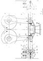
- Figure 1 is a front view of the general structure of the needling machine of the present invention. The machine is provided with a transmission crank mechanism including two main counter-rotating connecting rods and two auxiliary connecting rods to control the vertical movement of the needle-holder beam, the parts of the machine being shown in their intermediate or central position of operation;
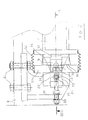
- Figure 2 is an enlarged view of the left end of the auxiliary connecting rod of the machine of Figure 1, the view of the right end being identical;
- Figure 3 is a cross-sectional view along the line III-III of the connecting rod end of Figure 2, the view of the other end being identical;
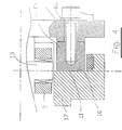
- Figure 4 is an enlarged view of a detail of the view of Figure 3;
- Figure 5 is a cross-sectional view along line V-V of the small end of left main connecting rod, turned by 90°, of Figure 1, the view of small end of the right main connecting rod being identical, and finally;
- Figure 6 illustrates one side (left side) of the machine of Figure 1 with the parts at different positions of top and bottom dead center, the other side of the machine being identical.
- As shown in Figure 1, the needling machine includes two substantially identical and specular mechanisms, joined to the support (or yoke) 1 of the needle-holder beam 2.
- Corresponding parts of the two mechanisms shall be indicated with the same reference symbols, but with an apostrophe (') for the parts of one of the mechanisms.
- With reference to Figure 1, the vertical reciprocating movement is transmitted to the support 1 by means of a crank mechanism.
- The crank mechanism includes two vertical counter-rotating main connecting
rods 3, 3', driven by thecranks 4, 4'. Eachrod 3,3' has asmall end 5, 5' which is connected to the support 1 by means of arotation pivot 6, 6'. - According to the invention, two auxiliary connecting
rods 7, 7', orthogonal to the main connectingrods 3, 3', are each installed at the opposite sides of the support 1. One end of each of therods 7, 7' is hinged by means of therotation pivots 6, 6' to the main connectingrods 3, 3'. The other end of each auxiliary connectingrod 7, 7' is joined to themachine structure 8 by means of a horizontally slidingblock 9, 9' and acircular profile 10, 10', that co-operates with a fixedflat profile 11, 11' of the structure. - The following description shall be made with reference to only one of the mechanisms, but it is obvious that both mechanisms operate in the same manner.
- With particular reference to Figures 2, 3 and 4, the
sliding block 9 is mounted on anaxial appendix 12 of the auxialiary connectingrod 7 by arotation pivot 13.Rotation pivot 13 crossesappendix 12 and is parallel to therotation pivot 6 of the main connectingrod 3. - Sliding
block 9 is formed in two parts that are mounted around the protruding ends of thepivot 13 by bearings and locked together by aclamp 14. - In one embodiment,
circular profile 10 has abody 15 fixed to the end of the auxiliary connectingrod 7 byhorizontal screws 16. Thecircular profile 10 has a bending radius equal to the distance between the axle ofrotation pivot 13 of auxialiary connectingrod 7 and the axle of therotation pivot 6 of the main connectingrod 3. A fixedflat profile 11 communicates with mobilecircular profile 10.Profile 11 has a flat surface perpendicular to the axle of the connectingrod 3 of thebody 17, which is fixed to anarm 18 of the structure byhorizontal screws - Other
vertical screws 21 fix thearm 18 to themachine structure 8. Thebody 17 has acavity 22, in which thesliding block 9 can slide between two guide walls, theupper guide wall 23 and thelower guide wall 24. - During operation of the crank mechanism, the sliding
block 9 slides in thecavity 22 between two extreme axial positions. - Mobile
circular profile 10 rolls on the fixedflat profile 11, and simultaneously, the auxiliary connectingrod 7 is angularly oscillated in a vertical plane, pivoting around therotation pivot 13. The contact between theprofiles fixed surface 11, and through the axle also being in different vertical positions, of therotation pivot 6 of the main connectingrod 3. - In detail, when the
sliding block 9 reaches the extreme internal position, the main connectingrod 3 and the auxiliary connectingrod 7 are in their central or intermediate positions, and when thesliding block 9 is in its extreme external position, the connecting rods are in top dead center or bottom dead center positions. - The top or bottom dead center positions reached by the connecting
rods sliding block 9 is in the extreme external position are shown in the Figure 6. In Figure 6, A indicates the top dead center position and B indicates the bottom dead center position. - Further, in Figure 6, LC, LS, LI indicate the outlines of the three parallel planes on which the contact lines between the
conjugate profiles rods - The rolling coupling of conjugated
profiles small end 5 of the main connectingrod 3. Thesmall end 5 of the main connecting rod must necessarily move along a vertical line assuring the perfect vertical motion of the reciprocating movement of the support 1 and needle-holder beam 2. - Naturally, perfect vertical operation can be obtained by other constructive arrangements suggested by the invention, particularly by the use of a
sole rotation pivot 6 for the connection of the ends of connectingrods - In fact, Figure 5 shows that the
pivot 6 is joined to thesmall end 5 of the main connecting rod 3 (shown turned by 90°) by alocking clamp 25, and to the support 1 of the needle-holder beam 2.Pivot 6 is further joined to the end of the auxiliary connectingrod 7 through therelated bearings - In detail, the connecting
rod 7 is joined to thepivot 6 byfork end 28. The bearings are locked on thepivot 6 by means ofscrews - The two ends of the
pivot 6 are closed by twoprotective covers 29 that are fixed to thefork 28 byscrews 30. The covers are provided with lubricators orunions 31 for the introduction of lubrication grease into the inside of thecovers 29. -
Bodies profiles conjugated profiles sliding block 9 andguide surfaces - In order to allow quick and easy replacement of
bodies rod 7 is made byscrews - Screws 20 and 21 allow the fastening of parts and further the necessary adjustment operations.
- To keep the end of the auxiliary connecting
rod 7 and the grease introduced therein within the inside of thebody 17, so as to lubricate theprofiles sliding block 9, and to avoid any escape of grease which could possibly damage the material being processed, acylindrical protection binding 32 is provided. - As shown in Figure 2, binding 32 comprises a bellows fixed to the outside of
bodies - The bellows allow the
small end 5 of the main connectingrod 3 to traverse, caused by the rolling action of thecircular profile 10 on theflat profile 11. Further, the bellows guarantees protection against dust. - The control device of the present invention eliminates all drawbacks suffered by known systems. In fact, it allows adjustments to be made very simply by the screws. Moreover, the rotation speed of the mechanism can be high, as the surfaces in contact are reduced to a minimum and the angular oscillations of auxiliary connecting
rods 7 are only of a few degrees, in the order of 4-5°. - Further, loss of lubricant does not occur because the grease is kept within by
protective bellows 32. - Finally, due to optimal lubrication that is achieved in this manner, jamming between the various parts of the device is avoided.
- The invention is shown with reference to a crank mechanism having two counter-rotating connecting rods. However, a crank mechanism having one main connecting rod can be used. In this case, the
auxiliary connecting rods 7 shall be two ones instead of one connectingrod 7, for each side of the support 1. If so, anauxiliary connecting rod 7 of each pair shall be hinged to thesmall end 5 of the main connectingrod 3, while the otherauxiliary connecting rod 7 shall be simply hinged to the support 1. - Both connecting rods shall be coupled by the second ends to the structure in the manner described above.
- Although the present invention has been described in relation to particular embodiments thereof, many other variations and modifications and other uses will become apparent to those skilled in the art.
Claims (13)
- A control system for the rectilinear vertical reciprocating movement of a needle-holder beam (2) in a needling machine in which the movement of the beam is transmitted from a motor through a crank mechanism with a main connecting rod (3) having its small end (5) hinged to a support (1) of the needle-holder beam (2), including at least two auxiliary connecting rods (7) one connected to either side of the needle-holder beam (2), each auxiliary connecting rod (7) having its first end hinged to the small end (5) of the main connecting rod (3) and its second end providing a movable profile (10) which co-operates with a conjugate fixed profile (11) of the machine structure for allowing the auxiliary connecting rod (7) to oscillate angularly in a vertical plane during operation of the crank mechanism, with the pair of conjugated profiles (10, 11) being in rolling engagement and constantly in contact with each other, with a sliding movement occurring between the end of the auxiliary connecting rod (7) and said machine structure,
characterised in that a sliding block (9) is hinged to said second end of the auxiliary connecting rod (7), the sliding block being horizontally movable to maintain the line of contact between said pair of conjugated profiles (10, 11) always in a horizontal plane which includes the hinge axis between the main and auxiliary connecting rods (3, 7). - The system of claim 1, wherein the sliding block (9) is hinged to an axial appendix (12) at said second end of the auxiliary connecting rod (7) by a rotation pivot (13) which extends parallel to a rotation pivot (6) hinging the auxiliary connecting rod (7) to the main connecting rod (3).
- The system of claim 2, wherein the sliding block (9) is connected to said axial appendix (12) by a clamp (14).
- The system of any preceding claim, wherein the movable profile (10) provided at said second end of the auxiliary connecting rod (7) is a circular profile with a radius equal to the distance between the hinge axis of the small end (5) of the main connecting rod (3) and the axis of the rotation pivot (13) at said second end of the auxiliary connecting rod (7), and wherein said fixed profile (11) is flat.
- The system of claim 4, wherein said circular profile is provided on a segment (15) fixed to said second end of the auxiliary connecting rod (7) by adjusting screws (16) and said flat profile is provided on a body (17) fixed to said machine structure by adjusting screws (19, 20), said body (17) forming a cavity (22) with guide walls (23, 24) for guiding said sliding block (9).
- The system of claim 5, wherein said body (17) is connected to a supporting arm (18) which in turn is connected to the machine structure by adjusting screws (21).
- The system of any preceding claim, wherein the elements (15, 17) provided with said conjugate profiles (10, 11) are interconnected by external bellows (32) for protection against dust and loss of lubricant.
- The system of any preceding claim, wherein the small end of the main connecting rod (3), said first end of the auxiliary connecting rod (7) and the support (1) of the needle-holder beam (2) are rotatably interconnected by a common rotation pivot (6).
- The system of claim 8, wherein said first end of the auxiliary connecting rod (7) engages said rotation pivot (6) by a terminal fork (28).
- The system of claim 8 or 9, wherein the small end of the main connecting rod (3) is connected to said rotation pivot (6) by a clamp (25).
- The system of any of claims 8 to 10, wherein the ends of said rotation pivot (6) are protected by covers (29) having means for introducing a lubricant.
- The system of any preceding claim, wherein said crank mechanism includes two counter-rotating main connecting rods (3), one hinged to either side of the support (1) of the needle-holder beam (28).
- The system of any of claims 1 to 11, wherein said crank mechanism includes a main connecting rod (3) hinged to an intermediate point of the support (1) of the needle-holder beam (2) and two pairs of interconnected auxiliary connecting rods, one pair connected to either side of said support (1), with only one auxiliary connecting rod of each pair being hinged to the rotation pivot (6) of the main connecting rod (3) and the other being hinged to said support (1).
Applications Claiming Priority (3)
| Application Number | Priority Date | Filing Date | Title |
|---|---|---|---|
| ITMI921201 | 1992-05-19 | ||
| ITMI921201A IT1255727B (en) | 1992-05-19 | 1992-05-19 | ALTERNATIVE VERTICAL RECTILINEAL MOVEMENT CONTROL SYSTEM OF THE NEEDLE BEAM OF A NEEDLE MACHINE |
| PCT/IT1993/000051 WO1993023597A1 (en) | 1992-05-19 | 1993-05-17 | Control system for the rectilinear vertical reciprocating movement of the needle-holder beam in a needling machine |
Publications (2)
| Publication Number | Publication Date |
|---|---|
| EP0596097A1 EP0596097A1 (en) | 1994-05-11 |
| EP0596097B1 true EP0596097B1 (en) | 1997-01-22 |
Family
ID=11363322
Family Applications (1)
| Application Number | Title | Priority Date | Filing Date |
|---|---|---|---|
| EP93913467A Expired - Lifetime EP0596097B1 (en) | 1992-05-19 | 1993-05-17 | Control system for the rectilinear vertical reciprocating movement of the needle-holder beam in a needling machine |
Country Status (6)
| Country | Link |
|---|---|
| US (1) | US5390556A (en) |
| EP (1) | EP0596097B1 (en) |
| AT (1) | ATE148184T1 (en) |
| DE (1) | DE69307657T2 (en) |
| IT (1) | IT1255727B (en) |
| WO (1) | WO1993023597A1 (en) |
Cited By (2)
| Publication number | Priority date | Publication date | Assignee | Title |
|---|---|---|---|---|
| DE102007031728A1 (en) | 2007-07-06 | 2009-01-08 | Oerlikon Textile Gmbh & Co. Kg | needle loom |
| EP2460920A1 (en) | 2010-12-01 | 2012-06-06 | Texnology S.R.L | Needling device |
Families Citing this family (14)
| Publication number | Priority date | Publication date | Assignee | Title |
|---|---|---|---|---|
| AT400152B (en) * | 1994-04-28 | 1995-10-25 | Fehrer Textilmasch | DEVICE FOR NEEDING A FLEECE |
| AT400583B (en) * | 1994-06-27 | 1996-01-25 | Fehrer Textilmasch | DEVICE FOR NEEDING A FLEECE |
| AT400584B (en) * | 1994-06-27 | 1996-01-25 | Fehrer Ernst | DEVICE FOR NEEDING A FLEECE |
| GB2290564B (en) * | 1994-06-27 | 1998-01-28 | Fehrer Textilmasch | Apparatus for needling a nonwoven web |
| US5732453A (en) * | 1995-09-15 | 1998-03-31 | Oskar Dilo Maschinenfabrik Kg | Needle bar driving apparatus of a needle loom |
| DE19730532A1 (en) * | 1997-07-16 | 1999-01-21 | Dilo Kg Maschf Oskar | Needle machine |
| DE19822725B4 (en) * | 1998-05-20 | 2006-09-28 | Oskar Dilo Maschinenfabrik Kg | Apparatus for consolidating a fibrous nonwoven web |
| AT411271B (en) | 2001-04-19 | 2003-11-25 | Fehrer Textilmasch | DEVICE FOR NEEDING A FLEECE |
| AT411272B (en) * | 2001-10-23 | 2003-11-25 | Fehrer Textilmasch | DEVICE FOR NEEDING A FLEECE |
| DE10328187B3 (en) * | 2003-06-24 | 2005-05-25 | Cnh Baumaschinen Gmbh | Storage between components on construction machinery |
| KR100877346B1 (en) | 2007-06-13 | 2009-01-07 | 한국생산기술연구원 | Needle punching machine |
| US8156618B2 (en) * | 2007-08-04 | 2012-04-17 | Tilman Reutter | Device for needling a fibrous web |
| DE102007041040B4 (en) | 2007-08-29 | 2009-07-09 | ERKO Trützschler GmbH | Needle machine with needle bar guide |
| CN102345211A (en) * | 2011-09-26 | 2012-02-08 | 常熟市鑫泰机械设备有限公司 | Stroke guide mechanism of needling machine |
Family Cites Families (13)
| Publication number | Priority date | Publication date | Assignee | Title |
|---|---|---|---|---|
| US739427A (en) * | 1902-07-05 | 1903-09-22 | Bliss E W Co | Drawing-press. |
| DE438855C (en) * | 1924-11-07 | 1926-12-28 | E H Hugo Junkers Dr Ing | Oscillating roller bearings |
| US1783403A (en) * | 1929-01-24 | 1930-12-02 | Waterbury Farrel Foundry Co | Connection |
| US2688296A (en) * | 1950-07-22 | 1954-09-07 | Danly Mach Specialties Inc | Triple action reciprocating crown press |
| US2896457A (en) * | 1956-07-18 | 1959-07-28 | Fed Machine & Welder Company | Variable stroke press |
| US3112657A (en) * | 1957-11-01 | 1963-12-03 | William F Huck | Reciprocation balancing mechanism |
| FR1560026A (en) * | 1968-03-28 | 1969-03-14 | ||
| AT326380B (en) * | 1972-10-06 | 1975-12-10 | Fehrer Ernst Gmbh | NEEDLE DEVICE FOR TRACKS, IN PARTICULAR FIBER FIBER FIBER OR FELT |
| US3923313A (en) * | 1975-05-22 | 1975-12-02 | Case Co J I | Self-adjusting grease-sealed articular joint |
| DE7717626U1 (en) * | 1977-06-03 | 1977-09-29 | Oskar Dilo Maschinenfabrik, Kg, 6930 Eberbach | NEEDLE FELTING MACHINE WITH A GUIDE DEVICE FOR THE NEEDLE BAR |
| US4629350A (en) * | 1984-12-14 | 1986-12-16 | Lark Equipment Company | Tolerance compensating joint |
| US4800767A (en) * | 1987-06-08 | 1989-01-31 | Builders Equipment Company | Acceleration control device for a hydraulic drive unit |
| US4777706A (en) * | 1987-09-14 | 1988-10-18 | Morrison Berkshire, Inc. | Apparatus for manufacturing endless needled paper machine felts |
-
1992
- 1992-05-19 IT ITMI921201A patent/IT1255727B/en active IP Right Grant
-
1993
- 1993-05-17 DE DE69307657T patent/DE69307657T2/en not_active Expired - Fee Related
- 1993-05-17 WO PCT/IT1993/000051 patent/WO1993023597A1/en not_active Ceased
- 1993-05-17 EP EP93913467A patent/EP0596097B1/en not_active Expired - Lifetime
- 1993-05-17 AT AT93913467T patent/ATE148184T1/en not_active IP Right Cessation
-
1994
- 1994-01-18 US US08/182,094 patent/US5390556A/en not_active Expired - Fee Related
Cited By (4)
| Publication number | Priority date | Publication date | Assignee | Title |
|---|---|---|---|---|
| DE102007031728A1 (en) | 2007-07-06 | 2009-01-08 | Oerlikon Textile Gmbh & Co. Kg | needle loom |
| WO2009007308A1 (en) * | 2007-07-06 | 2009-01-15 | Oerlikon Textile Gmbh & Co. Kg | Needling machine |
| DE102007031728B4 (en) * | 2007-07-06 | 2016-01-14 | Oerlikon Textile Gmbh & Co. Kg | needle loom |
| EP2460920A1 (en) | 2010-12-01 | 2012-06-06 | Texnology S.R.L | Needling device |
Also Published As
| Publication number | Publication date |
|---|---|
| EP0596097A1 (en) | 1994-05-11 |
| IT1255727B (en) | 1995-11-15 |
| ATE148184T1 (en) | 1997-02-15 |
| ITMI921201A1 (en) | 1993-11-19 |
| US5390556A (en) | 1995-02-21 |
| ITMI921201A0 (en) | 1992-05-19 |
| WO1993023597A1 (en) | 1993-11-25 |
| DE69307657D1 (en) | 1997-03-06 |
| DE69307657T2 (en) | 1997-09-11 |
Similar Documents
| Publication | Publication Date | Title |
|---|---|---|
| US5390556A (en) | Control system for the rectilinear vertical reciprocating movement in a needling machine | |
| EP0928646B1 (en) | Bending device | |
| US4996866A (en) | Orientable bending assembly | |
| CA2228623C (en) | Device for swinging a roll for a moving web | |
| KR20170051342A (en) | Shedding mechanism comprising a level adjustment device and weaving machine including said mechanism | |
| US3878883A (en) | Symmetrical synchronized belt-steering and tensioning system and apparatus for twin-belt continuous metal casting machines | |
| JP2749536B2 (en) | Girderless clamping system for injection molding machines | |
| US3949805A (en) | Symmetrical belt tensioning system and apparatus for twin-belt continuous casting machines | |
| CA1039040A (en) | Compactor shoe adjustment for compressive shrinking machines | |
| US6474528B2 (en) | Device for swiveling a rotary frame | |
| US4829842A (en) | Spur gearing for the driving of a roller shell | |
| EP1145791A1 (en) | Rotary drum type flying shear | |
| US4485693A (en) | Eccentric-operated vibrating apparatus | |
| US4332994A (en) | Apparatus for resistance welding of can bodies | |
| US4480678A (en) | Apparatus for controlling and guiding oscillations of a continuous casting mold | |
| US4989488A (en) | Drive mechanism for an oscillating tool, especially a saw blade | |
| US3963068A (en) | Symmetrical synchronized belt-steering system and apparatus for twin-belt continuous metal casting machines | |
| US6463962B2 (en) | Device for guiding the knife-supporting beams in a jacquard machine | |
| KR20060049731A (en) | Looper driving device of sewing machine | |
| KR100263394B1 (en) | Swing Self Positioning Support for Pipe Bending Machine | |
| GB2133809A (en) | Drawing apparatus for drawing slivers | |
| CN222386198U (en) | Web clamping device for H-shaped steel assembling machine | |
| EP0815966B1 (en) | Device for the crossed displacement of rolling rolls | |
| US9623461B2 (en) | Straightening machine | |
| CN111560702B (en) | Guide bar hanger and warp knitting machine having the same |
Legal Events
| Date | Code | Title | Description |
|---|---|---|---|
| PUAI | Public reference made under article 153(3) epc to a published international application that has entered the european phase |
Free format text: ORIGINAL CODE: 0009012 |
|
| 17P | Request for examination filed |
Effective date: 19940110 |
|
| AK | Designated contracting states |
Kind code of ref document: A1 Designated state(s): AT BE DE ES FR |
|
| 17Q | First examination report despatched |
Effective date: 19950201 |
|
| GRAG | Despatch of communication of intention to grant |
Free format text: ORIGINAL CODE: EPIDOS AGRA |
|
| GRAH | Despatch of communication of intention to grant a patent |
Free format text: ORIGINAL CODE: EPIDOS IGRA |
|
| GRAH | Despatch of communication of intention to grant a patent |
Free format text: ORIGINAL CODE: EPIDOS IGRA |
|
| GRAA | (expected) grant |
Free format text: ORIGINAL CODE: 0009210 |
|
| AK | Designated contracting states |
Kind code of ref document: B1 Designated state(s): AT BE DE ES FR |
|
| PG25 | Lapsed in a contracting state [announced via postgrant information from national office to epo] |
Ref country code: ES Free format text: THE PATENT HAS BEEN ANNULLED BY A DECISION OF A NATIONAL AUTHORITY Effective date: 19970122 Ref country code: BE Effective date: 19970122 |
|
| REF | Corresponds to: |
Ref document number: 148184 Country of ref document: AT Date of ref document: 19970215 Kind code of ref document: T |
|
| REF | Corresponds to: |
Ref document number: 69307657 Country of ref document: DE Date of ref document: 19970306 |
|
| RAP2 | Party data changed (patent owner data changed or rights of a patent transferred) |
Owner name: NENCINI, ANTONIO Owner name: NENCINI, MASSIMO |
|
| ET | Fr: translation filed | ||
| PGFP | Annual fee paid to national office [announced via postgrant information from national office to epo] |
Ref country code: FR Payment date: 19970603 Year of fee payment: 5 |
|
| PLBE | No opposition filed within time limit |
Free format text: ORIGINAL CODE: 0009261 |
|
| STAA | Information on the status of an ep patent application or granted ep patent |
Free format text: STATUS: NO OPPOSITION FILED WITHIN TIME LIMIT |
|
| 26N | No opposition filed | ||
| PG25 | Lapsed in a contracting state [announced via postgrant information from national office to epo] |
Ref country code: FR Free format text: LAPSE BECAUSE OF NON-PAYMENT OF DUE FEES Effective date: 19980531 |
|
| REG | Reference to a national code |
Ref country code: FR Ref legal event code: ST |
|
| PGFP | Annual fee paid to national office [announced via postgrant information from national office to epo] |
Ref country code: AT Payment date: 20010531 Year of fee payment: 9 |
|
| PGFP | Annual fee paid to national office [announced via postgrant information from national office to epo] |
Ref country code: DE Payment date: 20010723 Year of fee payment: 9 |
|
| PG25 | Lapsed in a contracting state [announced via postgrant information from national office to epo] |
Ref country code: AT Free format text: LAPSE BECAUSE OF NON-PAYMENT OF DUE FEES Effective date: 20020517 |
|
| PG25 | Lapsed in a contracting state [announced via postgrant information from national office to epo] |
Ref country code: DE Free format text: LAPSE BECAUSE OF NON-PAYMENT OF DUE FEES Effective date: 20021203 |