EP0596062B1 - Anti-icing system - Google Patents
Anti-icing system Download PDFInfo
- Publication number
- EP0596062B1 EP0596062B1 EP93909511A EP93909511A EP0596062B1 EP 0596062 B1 EP0596062 B1 EP 0596062B1 EP 93909511 A EP93909511 A EP 93909511A EP 93909511 A EP93909511 A EP 93909511A EP 0596062 B1 EP0596062 B1 EP 0596062B1
- Authority
- EP
- European Patent Office
- Prior art keywords
- fluid
- cavity
- exhaust
- nacelle
- flow
- Prior art date
- Legal status (The legal status is an assumption and is not a legal conclusion. Google has not performed a legal analysis and makes no representation as to the accuracy of the status listed.)
- Expired - Lifetime
Links
- 239000012530 fluid Substances 0.000 claims abstract description 120
- 238000007664 blowing Methods 0.000 claims description 17
- 238000010438 heat treatment Methods 0.000 claims description 12
- 238000000926 separation method Methods 0.000 claims description 8
- 238000011144 upstream manufacturing Methods 0.000 claims description 7
- 238000002347 injection Methods 0.000 claims description 4
- 239000007924 injection Substances 0.000 claims description 4
- 238000000034 method Methods 0.000 claims 4
- 238000010276 construction Methods 0.000 abstract 1
- 239000007789 gas Substances 0.000 description 24
- 238000013021 overheating Methods 0.000 description 7
- 230000006835 compression Effects 0.000 description 6
- 238000007906 compression Methods 0.000 description 6
- 238000002485 combustion reaction Methods 0.000 description 5
- 230000003068 static effect Effects 0.000 description 5
- 230000001419 dependent effect Effects 0.000 description 4
- 238000004891 communication Methods 0.000 description 3
- 230000007423 decrease Effects 0.000 description 3
- 238000012354 overpressurization Methods 0.000 description 3
- 238000012360 testing method Methods 0.000 description 3
- 239000002131 composite material Substances 0.000 description 2
- 230000000694 effects Effects 0.000 description 2
- 230000035515 penetration Effects 0.000 description 2
- 230000007704 transition Effects 0.000 description 2
- 238000007792 addition Methods 0.000 description 1
- 239000000853 adhesive Substances 0.000 description 1
- 230000001070 adhesive effect Effects 0.000 description 1
- 230000002411 adverse Effects 0.000 description 1
- 238000001816 cooling Methods 0.000 description 1
- 230000001186 cumulative effect Effects 0.000 description 1
- 238000013461 design Methods 0.000 description 1
- 239000000446 fuel Substances 0.000 description 1
- 230000003993 interaction Effects 0.000 description 1
- 238000002844 melting Methods 0.000 description 1
- 230000008018 melting Effects 0.000 description 1
- 239000007769 metal material Substances 0.000 description 1
- 239000000203 mixture Substances 0.000 description 1
- 230000000149 penetrating effect Effects 0.000 description 1
- 238000012827 research and development Methods 0.000 description 1
- 238000004904 shortening Methods 0.000 description 1
- 239000000243 solution Substances 0.000 description 1
- 238000013022 venting Methods 0.000 description 1
Images


Classifications
-
- F—MECHANICAL ENGINEERING; LIGHTING; HEATING; WEAPONS; BLASTING
- F02—COMBUSTION ENGINES; HOT-GAS OR COMBUSTION-PRODUCT ENGINE PLANTS
- F02C—GAS-TURBINE PLANTS; AIR INTAKES FOR JET-PROPULSION PLANTS; CONTROLLING FUEL SUPPLY IN AIR-BREATHING JET-PROPULSION PLANTS
- F02C7/00—Features, components parts, details or accessories, not provided for in, or of interest apart form groups F02C1/00 - F02C6/00; Air intakes for jet-propulsion plants
- F02C7/04—Air intakes for gas-turbine plants or jet-propulsion plants
- F02C7/047—Heating to prevent icing
-
- B—PERFORMING OPERATIONS; TRANSPORTING
- B64—AIRCRAFT; AVIATION; COSMONAUTICS
- B64D—EQUIPMENT FOR FITTING IN OR TO AIRCRAFT; FLIGHT SUITS; PARACHUTES; ARRANGEMENT OR MOUNTING OF POWER PLANTS OR PROPULSION TRANSMISSIONS IN AIRCRAFT
- B64D15/00—De-icing or preventing icing on exterior surfaces of aircraft
- B64D15/02—De-icing or preventing icing on exterior surfaces of aircraft by ducted hot gas or liquid
- B64D15/04—Hot gas application
-
- B—PERFORMING OPERATIONS; TRANSPORTING
- B64—AIRCRAFT; AVIATION; COSMONAUTICS
- B64D—EQUIPMENT FOR FITTING IN OR TO AIRCRAFT; FLIGHT SUITS; PARACHUTES; ARRANGEMENT OR MOUNTING OF POWER PLANTS OR PROPULSION TRANSMISSIONS IN AIRCRAFT
- B64D33/00—Arrangement in aircraft of power plant parts or auxiliaries not otherwise provided for
- B64D33/02—Arrangement in aircraft of power plant parts or auxiliaries not otherwise provided for of combustion air intakes
- B64D2033/0233—Arrangement in aircraft of power plant parts or auxiliaries not otherwise provided for of combustion air intakes comprising de-icing means
-
- Y—GENERAL TAGGING OF NEW TECHNOLOGICAL DEVELOPMENTS; GENERAL TAGGING OF CROSS-SECTIONAL TECHNOLOGIES SPANNING OVER SEVERAL SECTIONS OF THE IPC; TECHNICAL SUBJECTS COVERED BY FORMER USPC CROSS-REFERENCE ART COLLECTIONS [XRACs] AND DIGESTS
- Y02—TECHNOLOGIES OR APPLICATIONS FOR MITIGATION OR ADAPTATION AGAINST CLIMATE CHANGE
- Y02T—CLIMATE CHANGE MITIGATION TECHNOLOGIES RELATED TO TRANSPORTATION
- Y02T50/00—Aeronautics or air transport
- Y02T50/60—Efficient propulsion technologies, e.g. for aircraft
Definitions
- the present invention relates to an anti-icing system in a gas turbine powerplant and, more particularly, to exhaust means for anti-ice fluid flowing through a nacelle cavity.
- a typical aircraft powerplant such as an axial flow gas turbine engine, includes a nacelle which extends about the engine.
- the nacelle is the radially outermost structure of the powerplant.
- the nacelle extends forward of the gas turbine engine to define an inlet for working fluid to enter the gas turbine engine.
- the gas turbine engine includes a flowpath in communication with the fluid inlet of the nacelle.
- the flowpath extends sequentially through a compressor section, a combustion section and a turbine section.
- the compression section and turbine section include many components susceptible to impact damage, such as rotating blades which extend across the flowpath and interact with the working fluid.
- Safety is a primary concern in the design of powerplants to be used in aircraft applications.
- One hazard to be avoided is the build-up of ice on the engine and the structure surrounding the engine.
- the build-up of ice presents many problems. First, ice may add considerable weight to the engine and to the aircraft. Second, the build-up of ice near the inlet of the nacelle may adversely affect the flow of working fluid into and through the engine.
- the anti-ice system disclosed in U.S. Patent No. 4,688,745 is effective at reducing the build-up of ice on the inlet of the nacelle.
- the exhaust fluid removed through the exhaust holes is typically flowed into a chamber within the nacelle.
- the exhaust fluid exits the nacelle through a vent and flows into the external medium flowing about the nacelle. Flowing the exhaust gases through the nacelle structure may lead to overheating of the nacelle in the vicinity of the chamber.
- the fluid exiting the vent tends to be held against the outer barrel skin by the external medium flowing past the outer skin (the free stream). This may lead to overheating of the nacelle surface downstream of the vent. Overheating of the nacelle is especially significant if the nacelle is made from lightweight composite materials. These composite materials are typically bonded together with an adhesive having a lower melting temperature than traditional metallic materials.
- the rate of temperature decay downstream of the vent is dependent upon the size of the vent and a blowing parameter. Large values for the area of the vent result in a low rate of decay of temperature downstream of the vent. Small values of the blowing parameter, defined as the ratio of exhaust exit velocity to free stream velocity, also result in a low rate of decay of temperature downstream of the vent. The effects of vent size and blowing parameter on the rate of decay of temperature are cumulative.
- the vent also introduces aerodynamic penalties in the form of increased drag of the nacelle when the anti-ice system is shut off.
- the drag caused by the vent is dependent upon the size of the vent and the axial location of the vent. The larger the exit area of the vent or the closer the vent is to the leading edge of the nacelle, the greater the drag attributable to the vent.
- a solution to the overheating of the nacelle caused by the exhaust flow through the nacelle is to duct the exhaust flow from the cavity to the vent
- Ducting the exhaust fluid through the nacelle structure reduces the likelihood of overheating of the nacelle in the vicinity of the chamber, but also increases the size and weight of the nacelle structure. Attempts to decrease the bulk of the ducts by moving the exhaust vent forward, and thereby shortening the length of the duct, increase the aerodynamic drag of the vent. In addition, the duct does not prevent overheating of the nacelle surface downstream of the vent.
- EP-A-0205283 discloses an anti-ice system which channels spent hot air from within the nacelle through an exhaust duct to an exhaust aperture in the surface of the nacelle, and further provides a heat shield in the skin downstream of the exhaust aperture.
- FR-59222 also discloses ejecting spent hot air from within the nacelle.
- the invention is predicated in part upon recognition by the Applicants of the availability within the cavity of a dynamic pressure head to increase the velocity of the exhaust fluid exiting the cavity.
- Prior art exhaust means rely upon the static pressure differential between the cavity and the environment external to the cavity to produce the exhaust flow. This resulted in low exit velocities for the exhaust fluid and, consequently, large exhaust vents to provide an adequate, volumetric flow rate of exhaust fluid out of the cavity.
- the combination of small blowing parameter and large vent size resulted in overheating of the nacelle external surface.
- Using the dynamic pressure head available from the circumferentially flowing body of fluid increases the exit velocity and decreases the size of the exhaust vent required.
- an anti-icing system in a powerplant having a longitudinal axis, a source of heating fluid, and a nacelle defining a fluid inlet and a radially outer boundary for the powerplant, the nacelle having an annular cavity disposed about the inlet, the anti-icing system including means to flow heating fluid from the source to the cavity; means to inject heating fluid into the cavity, the injection means being adapted to generate a body of fluid flowing within the cavity with a circumferentially directed component of velocity; and means to exhaust fluid from the cavity into a medium external of the nacelle, characterised in that: the exhaust means comprises vanes within the cavity which are adapted to turn a portion of the fluid flowing within the cavity to a direction substantially normal to the direction of flow of the medium external of the nacelle and to eject the fluid from the cavity into the external medium at a flow velocity sufficient to penetrate the external medium.
- the exhaust means includes a plurality of aerodynamic vanes disposed within the cavity and on the radially outer portion of the nacelle, a plurality of vent slots disposed between adjacent vanes, an upstream fairing, and a downstream fairing, wherein the plurality of vanes are adapted to turn a portion of the circumferentially flowing body of fluid such that the turned portion of the fluid passes through the slots and out of the cavity.
- Each of the vanes extend in a direction normal to the principal direction of flow within the cavity.
- Each of the slots is disposed adjacent to, parallel with, and upstream of relative to the principal direction of flow within the cavity, one of the vanes.
- a principal feature of the present invention is the plurality of aerodynamically, bluntly shaped vanes disposed within the cavity. Another feature is the plurality of exhaust slots. A further feature is the fairings located upstream and downstream of the vanes and slots.
- a primary advantage of the present invention is the rate of decay of temperature downstream of the exhaust vent as a result of the exhaust fluid ejection angle, the blowing parameter of the exhaust means, and the size of the exhaust slots.
- the exhaust fluid is ejected through the plurality of small exhaust slots at an ejection angle substantially normal to the free stream flow direction and with sufficient velocity to penetrate the external medium flowing over the exhaust means.
- the penetration of the free stream creates a separation between the hot exhaust fluid and the nacelle and prevents reattachment of the exhaust fluid to the surface of the nacelle.
- Another advantage is the level of efficiency of the exhaust means as a result of the utilization of the dynamic pressure head within the cavity to produce the exhaust flow.
- the aerodynamic vanes interact with the fluid in the cavity to redirect a portion of it through the slots, rather than relying upon static pressure only to urge the fluid out of the cavity.
- a further advantage is the reduced aerodynamic drag of the vent, relative to prior art vents, as a result of the reduced size of the vent.
- the reduced vent size is a result of the increased velocity of the exhaust fluid ejected from the cavity.
- Another advantage is the tolerance of the exhaust means for non-circumferential flows within the cavity, such as helical flows, as a result of the bluntly shaped vanes.
- a further advantage is the minimal flow losses within the cavity as a result of the fairings which provide smooth changes in flow area and prevent flow separation from occurring. Minimizing flow losses within the cavity maximizes the pressure differential available to eject the exhaust fluid from the cavity.
- the invention is shown and described as means to exhaust fluid from a cavity having a circumferentially flowing body of fluid, the invention is equally applicable for cavities having other types of flow, such as a spiraling or helical flow about a circumferential axis through the annular cavity.
- FIG. 1 is a cross-sectional view of a gas turbine engine and a nacelle in accordance with the present invention.
- FIG. 2 is a cross-sectional view taken along line 2-2 of FIG. 1 to show a cross-sectional view of a plurality of exhaust vanes.
- FIG. 2 is a perspective view, partially cut away, of the exhaust means.
- FIG. 4 is a view taken along line 4-4 of FIG. 1, and shows the plurality of exhaust slots.
- FIG. 5 is a cross-sectional view of an exhaust vane.
- FIG. 6 is a plot of temperature decay as a function of a non-dimensionalized distance downstream of a vent.
- a gas turbine powerplant 12 is illustrated in FIG. 1.
- the powerplant 12 is disposed about a longitudinal axis 14 and includes an axial flow gas turbine engine 16 and a nacelle 18.
- the gas turbine engine 16 includes an axially extending flowpath 22, a compression section 24, a diffuser case 25, a combustion section 26, and a turbine section 28.
- Incoming fluid passes through the nacelle 18 and into the compression section 24 of the gas turbine engine 16.
- Working fluid is compressed within the compression section 24 which results in an increase in momentum of the working fluid and an increase in temperature of the working fluid.
- From the compression section 24 the working fluid flows through the diffuser case 25 and into the combustion section 26 where fuel is mixed with the working fluid and the mixture is combusted.
- the products of combustion are then expanded through the turbine section 28 and then flowed out of the gas turbine engine 16.
- the nacelle 18 extends forward of the gas turbine engine 16 and defines an inlet 32 for incoming fluid.
- the nacelle 18 includes an inner barrel 34, an outer barrel 36, a bulkhead 38, and an inlet shell 42.
- the inner barrel 34 defines a radially outer flow surface 44 for a portion of the flowpath of the gas turbine engine 16.
- the outer barrel 36 defines an outer flow surface 46 for the external medium flowing about the gas turbine engine 16.
- a radial separation between the inner barrel 34 and the outer barrel 36 defines an annular chamber 48 therebetween.
- the inlet shell 42 is the leading edge for the nacelle.
- the inlet shell 42 and the bulkhead 38 bound an annular shell cavity 52.
- the powerplant 12 includes an anti-ice system 54.
- the anti-ice system 54 includes a conduit 56, a nozzle 58, and exhaust means 62.
- the conduit 56 extends between the diffuser case 25 of the gas turbine engine 16 and the shell cavity 52.
- the conduit 56 may include a variety of valves and flow regulators to control the flow of fluid through the conduit.
- the diffuser case 25 is a source of high temperature, high pressure fluid.
- the nozzle 58 is attached to an outlet end 64 of the conduit 56 and extends within the shell cavity 52.
- the exhaust means 62 provides fluid communication between the shell cavity 52 and the external medium flowing about the powerplant 12.
- the exhaust means 62 is disposed on the radially outer portion and axially downstream end of the inlet shell 42.
- the exhaust means 62 may be located at various circumferential positions around the inlet 32, stability of the pressure field of the medium external to the exhaust means 62 may require consideration. As is well known, in aircraft applications a position 180° from top dead center is a region of stable pressure. Therefore, for aircraft applications it is suggested that the circumferential location of the exhaust means 62 be 180° from top dead center.
- the exhaust means 62 is located circumferentially adjacent to and upstream of relative to the flow within the shell cavity 52, the nozzle 58. This location removes fluid which has transferred heat as it travelled around the circumference of the shell cavity 52. In effect, the exhaust means 62 removes relatively cool exhaust fluid from the shell cavity 52.
- the exhaust means 62 includes a plurality of vanes 66, a plurality of exhaust slots 68, an upstream fairing, 69, a downstream fairing 70, and an axially adjacent wall 72.
- the plurality of exhaust vanes 66 extend radially inward from the inlet shell 42 and into the shell cavity 52.
- the plurality of vanes 66 also extend axially.
- Each vane 66 is aerodynamically shaped to engage the body of fluid flowing circumferentially within the shell cavity. As shown in FIG. 5, the vanes have a rounded leading edge 74 which adapts the vanes to engage with fluid flowing at off angles relative to the circumferential direction.
- the roundness of the vane leading edge 74 is defined by the ratio of leading edge 74 diameter d, measured as shown in FIG.
- the ratio d/t be between 0.4 and 0.6.
- the shape of the vanes 66 is also dependent upon the ratio of maximum thickness t to vane length l. It is suggested that the ratio t/l be between 0.3 and 0.5. While the vanes 66 have been described with respect to various ratios of length l, thickness t, and leading edge diameter d, it will be appreciated by those skilled in the art that the values of these ratios vary with application and the suggested ranges of values may be transgressed without departing from the scope of the invention.
- Each of the exhaust vanes 66 is circumferentially adjacent to and downstream of, relative to the direction of flow of the body of fluid within the shell cavity 52, one of the plurality of exhaust slots 68.
- the plurality of exhaust slots 68 extend radially through the inlet shell 42 and provide means of communication between the shell cavity 52 and the external medium.
- the exhaust slots 68 are circumferentially adjacent each other and extend in an axial direction as shown in FIG. 4.
- the upstream fairing 69 provides a smooth transition from the flow surface of the inlet shell 42 to the vanes 66.
- the downstream fairing 70 provides a smooth transition from the vanes 66 back to the flow surface of the inlet shell 42.
- the fairings 69, 70 eliminate abrupt changes in cross-sectional area within the shell cavity 52. In accordance with conventional fluid mechanics, the fairings 69, 70 produce smooth flow lines over the exhaust means 62 and uniformly distribute the exhaust flow through the exhaust slots 68. Without the fairings 69, 70, an unequal distribution of the flow through the slots would occur. Unequal distribution implies a flow separation, with corresponding flow losses and inefficiencies, within the shell cavity 52.
- FIGs. 1-4 show exhaust means having five (5) vanes and six (6) slots.
- the quantity and size of the vanes and slots is dependent upon the flow characteristics of the shell cavity and the flow rate of the source of high temperature, high pressure fluid.
- the quantity and size of the vanes and slots must be sufficient to prevent over-pressurization of the shell cavity when subjected to the maximum output of the source of hot fluid.
- the quantity and size of the vanes and slots must permit sufficient pressurization of the shell cavity to produce adequate flow velocity through the slots and penetration of the external flow.
- Temperature considerations dictate having multiple small slots to increase the rate of temperature decay of the fluid exiting each slot. A plurality of small slots produce a higher rate of temperature decay than a single large opening.
- compressor discharge fluid is removed from the diffuser case 25.
- the combustion section 26 is a source of high pressure, high temperature fluid (relative to the external medium) which may be used as heating fluid in the anti-ice system.
- the fluid is then flowed through the conduit 56, is ejected through the nozzle 58 and into the shell cavity 52.
- the conduit 56 provides means to flow the high temperature, high pressure fluid into the shell cavity 52.
- the fluid is ejected from the nozzle 58 in a direction tangential to the circumferential direction.
- the nozzle 58 provides means to inject fluid into the shell cavity 52 to generate a flowing body of fluid.
- the high pressure fluid exits the nozzle 58 with sufficient velocity to entrain the body of fluid within the shell cavity 52 and produce a body of fluid having a principal component of velocity directed in the circumferential direction.
- Exhaust means 62 is necessary to prevent over-pressurization of the shell cavity 52.
- the exhaust means 62 removes fluid from the radially outermost and axially downstream section of the shell cavity 52.
- the exhaust vanes 66 turn a portion of the flow such that the exhaust fluid is ejected from the cavity with an ejection angle ⁇ defined by the angle formed by the direction of the exhaust flow and the external surface of the nacelle, equal to 90°. Redirecting the flow to a direction substantially normal to the direction of flow of the external medium maximizes the rate of decay of temperature downstream of the exhaust slots 68.
- the exhaust vanes 66 utilize the dynamic pressure head within the shell cavity in addition to the static pressure head to urge the fluid through the exhaust slots 68.
- the combination of dynamic and static pressure heads produces an exhaust flow velocity sufficient to permit the exhaust flow to penetrate the external medium flowing by the exhaust slots 68.
- the separation region is a low pressure region which pulls in low temperature external medium.
- the exhaust fluid mixes with external medium rather than reattaching to the surface of the nacelle 18.
- the high velocity of the exhaust flow permits the total area of the exhaust slots 68 to be reduced relative to prior art exhaust vents.
- FIG. 6 is an illustration of test results of measured temperature decay as a function of distance downstream. Temperature decay is the ratio of the difference between surface temperature T and free stream temperature T ⁇ to the difference between vent exit temperature T 0 and free stream temperature T ⁇ .
- Distance downstream is shown as a ratio of x/D, where x is the actual distance and D is the effective diameter of the vent. Effective diameter D is the diameter of a circle equal in area to the vent. In this way the downstream distance is non-dimensional and the size of the vent is parametrically accounted for.
- the vanes provide means to turn a portion of the fluid flowing within the shell cavity to a direction substantially normal to the flow direction of the external medium flowing over the surface of the inlet shell in the vicinity of the exhaust means.
- the results used in curve “A” are for comparison purposes and are taken from "Film cooling with injection through Holes: Adiabatic Wall Temperatures Downstream of a circular Hole", ASME Paper No. 68-GT-19, authored by Goldstein, Eckert and Ramsey.
- the vanes also provide means to use the dynamic pressure head within the body of fluid flowing in the shell cavity.
- Using the dynamic pressure head in addition to the static pressure head increases the exit velocity through the exhaust means and decreases the size of the vent required relative to prior art exhaust vents. Higher exit velocity produces a higher blowing parameter ⁇ .
- Increasing the blowing parameter ⁇ increases the rate of temperature decay, as shown in FIG. 6.
- vent size D results in a larger value for x/D at a given distance X downstream of the exhaust means. Therefore, smaller vents produce increased rates of temperature decay for a given ejection angle ⁇ and blowing parameter ⁇ .
- the size of the vents or slots may be reduced by increasing the exit velocity, and thereby reducing the size of a slot needed to produce a required volumetric flow rate, and by increasing the number of slots, and thereby reducing the size of each slot.
- vanes 66 and slots 68 are shown in FIGs. 1-4 as extending in a direction normal to the circumferential direction, i.e. they extend axially.
- the vanes 66 are oriented in this direction to maximize the efficiency of the interaction between the body of fluid flowing within the shell cavity 52 and the exhaust means 62.
- the principal component of velocity for the body of fluid is directed in the circumferential direction.
- differing thermal boundary layers may build up around the internal flow surfaces of the shell cavity 52 and may result in the body of fluid within the cavity 52 having a non-circumferential component of velocity.
- the blunt shape of the vanes 66 adapt the exhaust means 62 to accommodate noncircumferential flow and to urge this type of flow into the exhaust means 62.
- vanes 66 and slots 68 may be canted relative to the longitudinal axis 14. Canting the vanes 66 may provide more efficient engagement of the exhaust means 62 with the noncircumferential flow within the shell cavity 52. For typical vanes, efficient engagement anticipates vanes extending in a direction substantially normal to the principal direction of the flow the vanes are engaged with.
- the diffuser case 25 was described as the source of high temperature, high pressure fluid, other sections of the powerplant 12 may function as a source of high temperature, high pressure fluid.
- the compression section 24 may be used.
- the exhaust means 62 though shown and described as ejecting fluid radially outboard of the nacelle, may be disposed to eject fluid radially inward such that the exhausted fluid is recycled into the gas turbine engine 16.
Landscapes
- Engineering & Computer Science (AREA)
- Chemical & Material Sciences (AREA)
- Combustion & Propulsion (AREA)
- Aviation & Aerospace Engineering (AREA)
- Mechanical Engineering (AREA)
- General Engineering & Computer Science (AREA)
- Structures Of Non-Positive Displacement Pumps (AREA)
- Wind Motors (AREA)
- Other Air-Conditioning Systems (AREA)
Abstract
Description
- The present invention relates to an anti-icing system in a gas turbine powerplant and, more particularly, to exhaust means for anti-ice fluid flowing through a nacelle cavity.
- A typical aircraft powerplant, such as an axial flow gas turbine engine, includes a nacelle which extends about the engine. The nacelle is the radially outermost structure of the powerplant. The nacelle extends forward of the gas turbine engine to define an inlet for working fluid to enter the gas turbine engine. The gas turbine engine includes a flowpath in communication with the fluid inlet of the nacelle. The flowpath extends sequentially through a compressor section, a combustion section and a turbine section. The compression section and turbine section include many components susceptible to impact damage, such as rotating blades which extend across the flowpath and interact with the working fluid.
- Safety is a primary concern in the design of powerplants to be used in aircraft applications. One hazard to be avoided is the build-up of ice on the engine and the structure surrounding the engine. The build-up of ice presents many problems. First, ice may add considerable weight to the engine and to the aircraft. Second, the build-up of ice near the inlet of the nacelle may adversely affect the flow of working fluid into and through the engine.
- Another concern with powerplants is the useful life of the powerplant and components. The build-up of ice near the inlet of the engine may lead to large pieces of ice breaking loose from the inlet and flowing into the gas turbine engine. Ice flowing into and through the engine may damage components within the engine such as the blades and components attached to the nacelle, such as inlet acoustic panels. The damaged components may then require replacement.
- Not surprisingly anti-ice systems for the inlet area of nacelles have been the focus of a significant amount of research and development within the aircraft industry. An example of this is U.S. Patent No. 4,688,745 entitled "Swirl Anti-Ice system" and issued to Rosenthal. This patent discloses a system for injecting hot gases into an annular cavity located on the leading edge of the nacelle. The cavity extends circumferentially about the inlet. The hot gases are injected into the cavity in a direction tangential to the circumferential direction. The tangential injection produces a circumferentially flowing body of hot gases within the cavity. Exhaust vents or holes located in a bulkhead of the nacelle allow gases within the cavity to escape into the external medium flowing around the powerplant. The venting of the anti-ice fluid prevents over-pressurization of the cavity in the event of an anti-ice fluid flow regulator failure. The exhaust holes lie in a plane parallel to the direction of flow to avoid direct impingement of the body of fluid on the exhaust holes.
- The anti-ice system disclosed in U.S. Patent No. 4,688,745 is effective at reducing the build-up of ice on the inlet of the nacelle. There are, however, drawbacks to the use of this anti-ice system. The exhaust fluid removed through the exhaust holes is typically flowed into a chamber within the nacelle. The exhaust fluid exits the nacelle through a vent and flows into the external medium flowing about the nacelle. Flowing the exhaust gases through the nacelle structure may lead to overheating of the nacelle in the vicinity of the chamber.
- Further, the fluid exiting the vent tends to be held against the outer barrel skin by the external medium flowing past the outer skin (the free stream). This may lead to overheating of the nacelle surface downstream of the vent. Overheating of the nacelle is especially significant if the nacelle is made from lightweight composite materials. These composite materials are typically bonded together with an adhesive having a lower melting temperature than traditional metallic materials. The rate of temperature decay downstream of the vent is dependent upon the size of the vent and a blowing parameter. Large values for the area of the vent result in a low rate of decay of temperature downstream of the vent. Small values of the blowing parameter, defined as the ratio of exhaust exit velocity to free stream velocity, also result in a low rate of decay of temperature downstream of the vent. The effects of vent size and blowing parameter on the rate of decay of temperature are cumulative.
- The vent also introduces aerodynamic penalties in the form of increased drag of the nacelle when the anti-ice system is shut off. The drag caused by the vent is dependent upon the size of the vent and the axial location of the vent. The larger the exit area of the vent or the closer the vent is to the leading edge of the nacelle, the greater the drag attributable to the vent.
- A solution to the overheating of the nacelle caused by the exhaust flow through the nacelle is to duct the exhaust flow from the cavity to the vent Ducting the exhaust fluid through the nacelle structure reduces the likelihood of overheating of the nacelle in the vicinity of the chamber, but also increases the size and weight of the nacelle structure. Attempts to decrease the bulk of the ducts by moving the exhaust vent forward, and thereby shortening the length of the duct, increase the aerodynamic drag of the vent. In addition, the duct does not prevent overheating of the nacelle surface downstream of the vent.
- EP-A-0205283 discloses an anti-ice system which channels spent hot air from within the nacelle through an exhaust duct to an exhaust aperture in the surface of the nacelle, and further provides a heat shield in the skin downstream of the exhaust aperture.
- FR-59222 also discloses ejecting spent hot air from within the nacelle.
- The above art notwithstanding, there is still a need to develop efficient anti-icing systems for the nacelle of a gas turbine powerplant.
- The invention is predicated in part upon recognition by the Applicants of the availability within the cavity of a dynamic pressure head to increase the velocity of the exhaust fluid exiting the cavity. Prior art exhaust means rely upon the static pressure differential between the cavity and the environment external to the cavity to produce the exhaust flow. This resulted in low exit velocities for the exhaust fluid and, consequently, large exhaust vents to provide an adequate, volumetric flow rate of exhaust fluid out of the cavity. The combination of small blowing parameter and large vent size resulted in overheating of the nacelle external surface. Using the dynamic pressure head available from the circumferentially flowing body of fluid increases the exit velocity and decreases the size of the exhaust vent required.
- According to the present invention, there is provided an anti-icing system in a powerplant having a longitudinal axis, a source of heating fluid, and a nacelle defining a fluid inlet and a radially outer boundary for the powerplant, the nacelle having an annular cavity disposed about the inlet, the anti-icing system including means to flow heating fluid from the source to the cavity; means to inject heating fluid into the cavity, the injection means being adapted to generate a body of fluid flowing within the cavity with a circumferentially directed component of velocity; and means to exhaust fluid from the cavity into a medium external of the nacelle, characterised in that:
the exhaust means comprises vanes within the cavity which are adapted to turn a portion of the fluid flowing within the cavity to a direction substantially normal to the direction of flow of the medium external of the nacelle and to eject the fluid from the cavity into the external medium at a flow velocity sufficient to penetrate the external medium. - According to a specific embodiment of the present invention, the exhaust means includes a plurality of aerodynamic vanes disposed within the cavity and on the radially outer portion of the nacelle, a plurality of vent slots disposed between adjacent vanes, an upstream fairing, and a downstream fairing, wherein the plurality of vanes are adapted to turn a portion of the circumferentially flowing body of fluid such that the turned portion of the fluid passes through the slots and out of the cavity. Each of the vanes extend in a direction normal to the principal direction of flow within the cavity. Each of the slots is disposed adjacent to, parallel with, and upstream of relative to the principal direction of flow within the cavity, one of the vanes.
- A principal feature of the present invention is the plurality of aerodynamically, bluntly shaped vanes disposed within the cavity. Another feature is the plurality of exhaust slots. A further feature is the fairings located upstream and downstream of the vanes and slots.
- A primary advantage of the present invention is the rate of decay of temperature downstream of the exhaust vent as a result of the exhaust fluid ejection angle, the blowing parameter of the exhaust means, and the size of the exhaust slots. The exhaust fluid is ejected through the plurality of small exhaust slots at an ejection angle substantially normal to the free stream flow direction and with sufficient velocity to penetrate the external medium flowing over the exhaust means. The penetration of the free stream creates a separation between the hot exhaust fluid and the nacelle and prevents reattachment of the exhaust fluid to the surface of the nacelle. Another advantage is the level of efficiency of the exhaust means as a result of the utilization of the dynamic pressure head within the cavity to produce the exhaust flow. The aerodynamic vanes interact with the fluid in the cavity to redirect a portion of it through the slots, rather than relying upon static pressure only to urge the fluid out of the cavity. A further advantage is the reduced aerodynamic drag of the vent, relative to prior art vents, as a result of the reduced size of the vent. The reduced vent size is a result of the increased velocity of the exhaust fluid ejected from the cavity. Another advantage is the tolerance of the exhaust means for non-circumferential flows within the cavity, such as helical flows, as a result of the bluntly shaped vanes. A further advantage is the minimal flow losses within the cavity as a result of the fairings which provide smooth changes in flow area and prevent flow separation from occurring. Minimizing flow losses within the cavity maximizes the pressure differential available to eject the exhaust fluid from the cavity.
- Although the invention is shown and described as means to exhaust fluid from a cavity having a circumferentially flowing body of fluid, the invention is equally applicable for cavities having other types of flow, such as a spiraling or helical flow about a circumferential axis through the annular cavity.
- The foregoing and other objects, features and advantages of the present invention will become more apparent in light of the following detailed description of the exemplary embodiments thereof, as illustrated in the accompanying drawings.
- FIG. 1 is a cross-sectional view of a gas turbine engine and a nacelle in accordance with the present invention.
- FIG. 2 is a cross-sectional view taken along line 2-2 of FIG. 1 to show a cross-sectional view of a plurality of exhaust vanes.
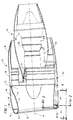
- FIG. 2 is a perspective view, partially cut away, of the exhaust means.
- FIG. 4 is a view taken along line 4-4 of FIG. 1, and shows the plurality of exhaust slots.
- FIG. 5 is a cross-sectional view of an exhaust vane.
- FIG. 6 is a plot of temperature decay as a function of a non-dimensionalized distance downstream of a vent.
- A
gas turbine powerplant 12 is illustrated in FIG. 1. Thepowerplant 12 is disposed about alongitudinal axis 14 and includes an axial flowgas turbine engine 16 and anacelle 18. Thegas turbine engine 16 includes anaxially extending flowpath 22, acompression section 24, adiffuser case 25, acombustion section 26, and aturbine section 28. Incoming fluid passes through thenacelle 18 and into thecompression section 24 of thegas turbine engine 16. Working fluid is compressed within thecompression section 24 which results in an increase in momentum of the working fluid and an increase in temperature of the working fluid. From thecompression section 24 the working fluid flows through thediffuser case 25 and into thecombustion section 26 where fuel is mixed with the working fluid and the mixture is combusted. The products of combustion are then expanded through theturbine section 28 and then flowed out of thegas turbine engine 16. - The
nacelle 18 extends forward of thegas turbine engine 16 and defines aninlet 32 for incoming fluid. Thenacelle 18 includes aninner barrel 34, anouter barrel 36, abulkhead 38, and aninlet shell 42. Theinner barrel 34 defines a radiallyouter flow surface 44 for a portion of the flowpath of thegas turbine engine 16. Theouter barrel 36 defines anouter flow surface 46 for the external medium flowing about thegas turbine engine 16. A radial separation between theinner barrel 34 and theouter barrel 36 defines anannular chamber 48 therebetween. Theinlet shell 42 is the leading edge for the nacelle. Theinlet shell 42 and thebulkhead 38 bound anannular shell cavity 52. - The
powerplant 12 includes ananti-ice system 54. Theanti-ice system 54 includes aconduit 56, anozzle 58, and exhaust means 62. Theconduit 56 extends between thediffuser case 25 of thegas turbine engine 16 and theshell cavity 52. Although not shown in FIG. 1, theconduit 56 may include a variety of valves and flow regulators to control the flow of fluid through the conduit. Thediffuser case 25 is a source of high temperature, high pressure fluid. Thenozzle 58 is attached to anoutlet end 64 of theconduit 56 and extends within theshell cavity 52. The exhaust means 62 provides fluid communication between theshell cavity 52 and the external medium flowing about thepowerplant 12. The exhaust means 62 is disposed on the radially outer portion and axially downstream end of theinlet shell 42. Although the exhaust means 62 may be located at various circumferential positions around theinlet 32, stability of the pressure field of the medium external to the exhaust means 62 may require consideration. As is well known, in aircraft applications a position 180° from top dead center is a region of stable pressure. Therefore, for aircraft applications it is suggested that the circumferential location of the exhaust means 62 be 180° from top dead center. - Referring now to FIGs. 2-4, the exhaust means 62 is located circumferentially adjacent to and upstream of relative to the flow within the
shell cavity 52, thenozzle 58. This location removes fluid which has transferred heat as it travelled around the circumference of theshell cavity 52. In effect, the exhaust means 62 removes relatively cool exhaust fluid from theshell cavity 52. - The exhaust means 62 includes a plurality of
vanes 66, a plurality ofexhaust slots 68, an upstream fairing, 69, adownstream fairing 70, and an axiallyadjacent wall 72. The plurality ofexhaust vanes 66 extend radially inward from theinlet shell 42 and into theshell cavity 52. The plurality ofvanes 66 also extend axially. Eachvane 66 is aerodynamically shaped to engage the body of fluid flowing circumferentially within the shell cavity. As shown in FIG. 5, the vanes have a rounded leadingedge 74 which adapts the vanes to engage with fluid flowing at off angles relative to the circumferential direction. The roundness of thevane leading edge 74 is defined by the ratio of leadingedge 74 diameter d, measured as shown in FIG. 5, to maximum thickness t, measured in the circumferential direction. To accommodate off angle flow within theshell cavity 52, it is suggested that the ratio d/t be between 0.4 and 0.6. The shape of thevanes 66 is also dependent upon the ratio of maximum thickness t to vane length l. It is suggested that the ratio t/l be between 0.3 and 0.5. While thevanes 66 have been described with respect to various ratios of length l, thickness t, and leading edge diameter d, it will be appreciated by those skilled in the art that the values of these ratios vary with application and the suggested ranges of values may be transgressed without departing from the scope of the invention. - Each of the
exhaust vanes 66 is circumferentially adjacent to and downstream of, relative to the direction of flow of the body of fluid within theshell cavity 52, one of the plurality ofexhaust slots 68. The plurality ofexhaust slots 68 extend radially through theinlet shell 42 and provide means of communication between theshell cavity 52 and the external medium. Theexhaust slots 68 are circumferentially adjacent each other and extend in an axial direction as shown in FIG. 4. - The
upstream fairing 69 provides a smooth transition from the flow surface of theinlet shell 42 to thevanes 66. Thedownstream fairing 70 provides a smooth transition from thevanes 66 back to the flow surface of theinlet shell 42. Thefairings shell cavity 52. In accordance with conventional fluid mechanics, thefairings exhaust slots 68. Without thefairings shell cavity 52. - FIGs. 1-4 show exhaust means having five (5) vanes and six (6) slots. The quantity and size of the vanes and slots is dependent upon the flow characteristics of the shell cavity and the flow rate of the source of high temperature, high pressure fluid. The quantity and size of the vanes and slots must be sufficient to prevent over-pressurization of the shell cavity when subjected to the maximum output of the source of hot fluid. In addition, the quantity and size of the vanes and slots must permit sufficient pressurization of the shell cavity to produce adequate flow velocity through the slots and penetration of the external flow. Temperature considerations dictate having multiple small slots to increase the rate of temperature decay of the fluid exiting each slot. A plurality of small slots produce a higher rate of temperature decay than a single large opening.
- During operation of the
gas turbine engine 16, compressor discharge fluid is removed from thediffuser case 25. Thecombustion section 26 is a source of high pressure, high temperature fluid (relative to the external medium) which may be used as heating fluid in the anti-ice system. The fluid is then flowed through theconduit 56, is ejected through thenozzle 58 and into theshell cavity 52. Theconduit 56 provides means to flow the high temperature, high pressure fluid into theshell cavity 52. As shown in Figs. 1 and 2, the fluid is ejected from thenozzle 58 in a direction tangential to the circumferential direction. Thenozzle 58 provides means to inject fluid into theshell cavity 52 to generate a flowing body of fluid. The high pressure fluid exits thenozzle 58 with sufficient velocity to entrain the body of fluid within theshell cavity 52 and produce a body of fluid having a principal component of velocity directed in the circumferential direction. - Exhaust means 62 is necessary to prevent over-pressurization of the
shell cavity 52. The exhaust means 62 removes fluid from the radially outermost and axially downstream section of theshell cavity 52. The exhaust vanes 66 turn a portion of the flow such that the exhaust fluid is ejected from the cavity with an ejection angle α defined by the angle formed by the direction of the exhaust flow and the external surface of the nacelle, equal to 90°. Redirecting the flow to a direction substantially normal to the direction of flow of the external medium maximizes the rate of decay of temperature downstream of theexhaust slots 68. - The exhaust vanes 66 utilize the dynamic pressure head within the shell cavity in addition to the static pressure head to urge the fluid through the
exhaust slots 68. The combination of dynamic and static pressure heads produces an exhaust flow velocity sufficient to permit the exhaust flow to penetrate the external medium flowing by theexhaust slots 68. By penetrating the external medium a separation is created between the hot exhaust fluid and thenacelle 18. The separation region is a low pressure region which pulls in low temperature external medium. As a result, the exhaust fluid mixes with external medium rather than reattaching to the surface of thenacelle 18. In addition, the high velocity of the exhaust flow permits the total area of theexhaust slots 68 to be reduced relative to prior art exhaust vents. - FIG. 6 is an illustration of test results of measured temperature decay as a function of distance downstream. Temperature decay is the ratio of the difference between surface temperature T and free stream temperature T∞ to the difference between vent exit temperature T0 and free stream temperature T∞. Distance downstream is shown as a ratio of x/D, where x is the actual distance and D is the effective diameter of the vent. Effective diameter D is the diameter of a circle equal in area to the vent. In this way the downstream distance is non-dimensional and the size of the vent is parametrically accounted for. The vanes provide means to turn a portion of the fluid flowing within the shell cavity to a direction substantially normal to the flow direction of the external medium flowing over the surface of the inlet shell in the vicinity of the exhaust means. Turning the exhaust flow normal to the free stream direction increases the rate of decay of temperature along the surface downstream of the exhaust means, as shown in FIG. 6. Curve "A" represents a circular vent with an ejection angle αA=35° and a blowing parameter βA=0.4. The results used in curve "A" are for comparison purposes and are taken from "Film cooling with injection through Holes: Adiabatic Wall Temperatures Downstream of a circular Hole", ASME Paper No. 68-GT-19, authored by Goldstein, Eckert and Ramsey. Curve "B" represents test results for a circular vent with an ejection angle αB=90° and a blowing parameter βB=0.4. Curve "C" represents test results for a slotted vent with an ejection angle αC=90° and a blowing parameter βC=0.4. Although turning the exhaust flow from a substantially tangential direction (αA=35°) to a direction normal to the free stream (αB=αC=90°) increases the rate of temperature decay dramatically, improvement in rate of temperature decay may also be produced by ejection angles as low as α=60°.
- The vanes also provide means to use the dynamic pressure head within the body of fluid flowing in the shell cavity. Using the dynamic pressure head in addition to the static pressure head increases the exit velocity through the exhaust means and decreases the size of the vent required relative to prior art exhaust vents. Higher exit velocity produces a higher blowing parameter β. Increasing the blowing parameter β increases the rate of temperature decay, as shown in FIG. 6. Curves "D" and "E" represent the results for circular and slotted vents, respectively, having a blowing parameter βD=βE=0.7. Curve "F" represents the results for a circular vent having a blowing parameter βF=1.2.
- Smaller vent size D results in a larger value for x/D at a given distance X downstream of the exhaust means. Therefore, smaller vents produce increased rates of temperature decay for a given ejection angle α and blowing parameter β. The size of the vents or slots may be reduced by increasing the exit velocity, and thereby reducing the size of a slot needed to produce a required volumetric flow rate, and by increasing the number of slots, and thereby reducing the size of each slot.
- It should be noted that the
vanes 66 andslots 68 are shown in FIGs. 1-4 as extending in a direction normal to the circumferential direction, i.e. they extend axially. Thevanes 66 are oriented in this direction to maximize the efficiency of the interaction between the body of fluid flowing within theshell cavity 52 and the exhaust means 62. The principal component of velocity for the body of fluid is directed in the circumferential direction. During operation, however, differing thermal boundary layers may build up around the internal flow surfaces of theshell cavity 52 and may result in the body of fluid within thecavity 52 having a non-circumferential component of velocity. The blunt shape of thevanes 66 adapt the exhaust means 62 to accommodate noncircumferential flow and to urge this type of flow into the exhaust means 62. In some situations, it may be desirable to angle thenozzle 58, or a plurality ofnozzles 58, to induce a spiralling or helical flow within theshell cavity 52. For such other flow conditions thevanes 66 andslots 68 may be canted relative to thelongitudinal axis 14. Canting thevanes 66 may provide more efficient engagement of the exhaust means 62 with the noncircumferential flow within theshell cavity 52. For typical vanes, efficient engagement anticipates vanes extending in a direction substantially normal to the principal direction of the flow the vanes are engaged with. - It should also be noted that, although the
diffuser case 25 was described as the source of high temperature, high pressure fluid, other sections of thepowerplant 12 may function as a source of high temperature, high pressure fluid. For instance, thecompression section 24 may be used. Additionally, the exhaust means 62, though shown and described as ejecting fluid radially outboard of the nacelle, may be disposed to eject fluid radially inward such that the exhausted fluid is recycled into thegas turbine engine 16. - Although the invention has been shown and described with respect to exemplary embodiments thereof, it should be understood by those skilled in the art that various changes, omissions, and additions may be made thereto, without departing from the scope of the invention which is defined by the claims.
Claims (13)
- An anti-icing system (54) in a powerplant (12) having a longitudinal axis (14), a source (25) of heating fluid, and a nacelle (18) defining a fluid inlet (32) and a radially outer boundary (44) for the powerplant, the nacelle having an annular cavity (52) disposed about the inlet, the anti-icing system including means (56) to flow heating fluid from the source to the cavity; means (58) to inject heating fluid into the cavity, the injection means being adapted to generate a body of fluid flowing within the cavity with a circumferentially directed component of velocity; and means (62) to exhaust fluid from the cavity into a medium external of the nacelle, characterised in that:
the exhaust means comprises vanes (66) within the cavity which are adapted to turn a portion of the fluid flowing within the cavity to a direction substantially normal to the direction of flow of the medium external of the nacelle and to eject the fluid from the cavity into the external medium at a flow velocity sufficient to penetrate the external medium. - The anti-icing system according to Claim 1, wherein the cavity is defined by an inlet shell (42), and wherein the exhaust means includes an exhaust slot (68) disposed on the radially outer portion of the inlet shell and an aerodynamically shaped exhaust vane (66), the exhaust vane being disposed on the inlet shell, extending radially into the cavity, and being adjacent to and extending parallel to the exhaust slot, the exhaust vane being adapted to engage the body of fluid flowing within the cavity and to urge a portion of the fluid through the exhaust slot.
- The anti-icing system according to Claim 2, further comprising a fairing (69) disposed upstream, relative to the direction of flow of the body of fluid within the cavity, of the exhaust vane and adapted to prevent flow separation from occurring.
- The anti-icing system according to Claim 2 or 3, further comprising a fairing (70), disposed downstream relative to the direction of flow of the body of fluid within the cavity, of the exhaust vane and adapted to prevent flow separation from occurring.
- The anti-icing system according to Claim 2, 3 or 4 wherein the exhaust vane has a maximum thickness t, measured in the circumferential direction, and a rounded leading edge having a leading edge diameter d, and wherein the ratio d/t is between 0.4 and 0.6.
- The anti-icing system according to any of claims 2 to 5, wherein the exhaust vane has a maximum thickness t, measured in the circumferential direction, and a length l, measured in the radial direction, and wherein the ratio t/l is between 0.3 and 0.5.
- The anti-icing system according to any of Claims 2 to 6, wherein the exhaust vane and exhaust slot extend in a direction normal to the direction of flow of the body of fluid within the cavity.
- The anti-icing system according to any of Claims 2 to 7, wherein the exhaust vane and exhaust slot are adapted to eject the fluid in a radially outward direction.
- The anti-icing system according to any preceding claim wherein the exhaust means turns the portion of the fluid such that the fluid is ejected from the cavity in a direction forming an angle α with the surface of the nacelle, the angle α being greater than or equal to 60°.
- The anti-icing system according to any preceding claim wherein the fluid being ejected has a blowing parameter β, defined as the ratio of the magnitude of velocity of the ejected fluid to the magnitude of velocity of the external medium flowing over the nacelle, and wherein the blowing parameter β is greater than or equal to 0.4.
- A method of preventing ice build-up on a nacelle (18) of an aircraft powerplant (12), the powerplant including a source (25) of heating fluid and an anti-icing system (54), the anti-icing system including means (56) to flow heating fluid from the source to a cavity (52) in the nacelle, means (58) to inject heating fluid into the cavity, and means (62) to exhaust fluid from the cavity, the method including the steps of flowing heating fluid from the source to the cavity; injecting heating fluid into the cavity such that the body of fluid within the cavity has a circumferentially directed component of velocity, and ejecting fluid from the cavity into a medium external to the nacelle, the fluid being ejected with a flow velocity sufficient to penetrate the external medium, characterised in that:
the step of ejecting fluid includes turning a portion of the fluid within the cavity to a direction substantially normal to the direction of flow of the external medium by means of an aerodynamic exhaust vane (66) and an exhaust slot (68), the exhaust vane being adapted to engage the body of fluid within the cavity to turn a portion of the fluid and urge the portion of the fluid through the exhaust slot. - The method according to Claim 11, wherein the step of ejecting fluid includes ejecting the fluid from the cavity in a direction forming an angle α with the surface of the nacelle, the angle α being greater than or equal to 60°.
- The method according to Claim 11 or 12 wherein the step of ejecting fluid includes ejecting the fluid with a blowing parameter β greater than 0.4, the blowing parameter β being defined as the ratio of the magnitude of velocity of the ejected fluid to the magnitude of velocity of the external medium flowing over the nacelle.
Applications Claiming Priority (3)
| Application Number | Priority Date | Filing Date | Title |
|---|---|---|---|
| US872575 | 1992-04-23 | ||
| US07/872,575 US5257498A (en) | 1992-04-23 | 1992-04-23 | Efficient anti-ice exhaust vent |
| PCT/US1993/003458 WO1993022548A1 (en) | 1992-04-23 | 1993-04-13 | Exhaust vent for de-icing system of aircraft nacelle |
Publications (2)
| Publication Number | Publication Date |
|---|---|
| EP0596062A1 EP0596062A1 (en) | 1994-05-11 |
| EP0596062B1 true EP0596062B1 (en) | 1997-07-02 |
Family
ID=25359880
Family Applications (1)
| Application Number | Title | Priority Date | Filing Date |
|---|---|---|---|
| EP93909511A Expired - Lifetime EP0596062B1 (en) | 1992-04-23 | 1993-04-13 | Anti-icing system |
Country Status (6)
| Country | Link |
|---|---|
| US (2) | US5257498A (en) |
| EP (1) | EP0596062B1 (en) |
| JP (1) | JP3326563B2 (en) |
| DE (1) | DE69311876T2 (en) |
| ES (1) | ES2105255T3 (en) |
| WO (1) | WO1993022548A1 (en) |
Cited By (1)
| Publication number | Priority date | Publication date | Assignee | Title |
|---|---|---|---|---|
| US7246480B2 (en) | 2004-11-04 | 2007-07-24 | Siemens Power Generation, Inc. | System for heating an air intake of turbine engine |
Families Citing this family (44)
| Publication number | Priority date | Publication date | Assignee | Title |
|---|---|---|---|---|
| GB9120113D0 (en) * | 1991-09-20 | 1992-09-23 | Short Brothers Plc | Thermal antiicing of aircraft structures |
| FR2771776B1 (en) | 1997-12-02 | 2000-01-28 | Aerospatiale | HOT AIR DISCHARGE DEVICE FOR REACTION ENGINE AIR INTAKE COVER WITH DEFROSTING CIRCUIT |
| US6354538B1 (en) * | 1999-10-25 | 2002-03-12 | Rohr, Inc. | Passive control of hot air injection for swirling rotational type anti-icing system |
| FR2802573B1 (en) | 1999-12-21 | 2002-02-15 | Aerospatiale Matra Airbus | HOT AIR DISCHARGE DEVICE FOR REACTION ENGINE AIR INTAKE COVER WITH DEFROSTING CIRCUIT |
| GB0211800D0 (en) * | 2002-05-22 | 2002-07-03 | Short Brothers Plc | An ice protection system for aircraft structures |
| US6910659B2 (en) | 2002-10-22 | 2005-06-28 | The Boeing Company | Method and apparatus for liquid containment, such as for aircraft fuel vessels |
| US7175136B2 (en) | 2003-04-16 | 2007-02-13 | The Boeing Company | Method and apparatus for detecting conditions conducive to ice formation |
| DE60329634D1 (en) | 2003-08-20 | 2009-11-19 | Boeing Co | METHOD AND SYSTEMS FOR DETERMINING TEMPERING CONDITIONS |
| US7137240B2 (en) * | 2004-08-18 | 2006-11-21 | Hamilton Sundstrand Corporation | Inlet muff anti-icing system for an auxiliary power unit |
| EP1674694B1 (en) * | 2004-12-23 | 2014-02-12 | Rolls-Royce plc | Compressor intake duct |
| US7331421B2 (en) | 2005-03-30 | 2008-02-19 | The Boeing Company | Flow restrictors for aircraft inlet acoustic treatments, and associated systems and methods |
| US20080044273A1 (en) * | 2006-08-15 | 2008-02-21 | Syed Arif Khalid | Turbomachine with reduced leakage penalties in pressure change and efficiency |
| US20080046407A1 (en) * | 2006-08-16 | 2008-02-21 | Microsoft Corporation | Application search interface |
| US7900872B2 (en) * | 2007-12-12 | 2011-03-08 | Spirit Aerosystems, Inc. | Nacelle inlet thermal anti-icing spray duct support system |
| US8061657B2 (en) | 2008-12-31 | 2011-11-22 | General Electric Company | Method and apparatus for aircraft anti-icing |
| FR2953254B1 (en) * | 2009-12-01 | 2012-01-20 | Airbus Operations Sas | AIR INLET HOOD FOR REACTION ENGINE AND HOT AIR MIXER FOR SUCH HOOD |
| US8869508B2 (en) | 2012-01-31 | 2014-10-28 | United Technologies Corporation | Gas turbine engine variable area fan nozzle control |
| US9593628B2 (en) | 2012-01-31 | 2017-03-14 | United Technologies Corporation | Gas turbine engine variable area fan nozzle with ice management |
| US9488067B2 (en) | 2014-01-14 | 2016-11-08 | The Boeing Company | Aircraft anti-icing systems having deflector vanes |
| US10378554B2 (en) | 2014-09-23 | 2019-08-13 | Pratt & Whitney Canada Corp. | Gas turbine engine with partial inlet vane |
| US10145301B2 (en) | 2014-09-23 | 2018-12-04 | Pratt & Whitney Canada Corp. | Gas turbine engine inlet |
| US9938848B2 (en) | 2015-04-23 | 2018-04-10 | Pratt & Whitney Canada Corp. | Rotor assembly with wear member |
| US9957807B2 (en) | 2015-04-23 | 2018-05-01 | Pratt & Whitney Canada Corp. | Rotor assembly with scoop |
| FR3041937B1 (en) * | 2015-10-05 | 2017-10-20 | Airbus Operations Sas | COMPARTMENTED STRUCTURE FOR THE ACOUSTIC TREATMENT AND DEFROSTING OF AN AIRCRAFT NACELLE AND AN AIRCRAFT NACELLE INCORPORATING THE SAID STRUCTURE |
| US10167085B2 (en) | 2016-01-27 | 2019-01-01 | General Electric Company | Nozzle and vane system for nacelle anti-icing |
| US10384786B2 (en) | 2016-02-05 | 2019-08-20 | United Technologies Corporation | Thermally biased valve and anti-icing system |
| US10189572B2 (en) * | 2016-05-02 | 2019-01-29 | The Boeing Company | Systems and methods for preventing ice formation on portions of an aircraft |
| US9849992B2 (en) | 2016-05-23 | 2017-12-26 | United Technologies Corporation | Inline pressure regulating valve assembly with inlet pressure bias |
| US10273884B2 (en) | 2016-06-09 | 2019-04-30 | Hamilton Sundstrand Corporation | Altitude compensating bleed valve |
| US10450955B2 (en) | 2016-07-06 | 2019-10-22 | United Technologies Corporation | Nacelle anti ice system |
| US10221765B2 (en) | 2016-08-26 | 2019-03-05 | Honeywell International Inc. | Anti-icing exhaust system |
| US10724540B2 (en) | 2016-12-06 | 2020-07-28 | Pratt & Whitney Canada Corp. | Stator for a gas turbine engine fan |
| US10690146B2 (en) | 2017-01-05 | 2020-06-23 | Pratt & Whitney Canada Corp. | Turbofan nacelle assembly with flow disruptor |
| US10436112B2 (en) * | 2017-06-26 | 2019-10-08 | The Boeing Company | Translating turning vanes for a nacelle inlet |
| US11208952B2 (en) * | 2018-07-03 | 2021-12-28 | Rohr, Inc. | Inlet—NAI exhaust hole definition for reduced D-duct resonance noise and diluted exhaust plume for thermal control |
| FR3086642A1 (en) * | 2018-09-28 | 2020-04-03 | Airbus Operations | TONAL NOISE SUPPRESSION OR REDUCTION DEVICE FOR AN AIRCRAFT POWDER DEFROSTING SYSTEM |
| US11199133B2 (en) * | 2018-12-17 | 2021-12-14 | Hamilton Sundstrand Corporation | Aircraft systems and methods utilizing waste heat in fuel |
| FR3092618B1 (en) | 2019-02-08 | 2021-02-19 | Safran Nacelles | Air inlet of an aircraft turbojet nacelle having ventilation openings for a flow of hot de-icing air |
| FR3092620B1 (en) | 2019-02-08 | 2021-03-05 | Safran Nacelles | Air inlet of an aircraft turbojet nacelle having ventilation openings for a flow of hot de-icing air |
| FR3092619B1 (en) | 2019-02-08 | 2021-03-19 | Safran Nacelles | Air inlet of an aircraft turbojet nacelle having ventilation openings for a flow of hot de-icing air |
| US20210107676A1 (en) * | 2019-10-11 | 2021-04-15 | General Electric Company | Aircraft Having an Aft Engine and Auxiliary Power Unit |
| US20210163141A1 (en) * | 2019-11-28 | 2021-06-03 | Pratt & Whitney Canada Corp. | Gas turbine engine, nacelle thereof, and associated method of operating a gas turbine engine |
| CN115234374B (en) * | 2022-07-26 | 2025-06-17 | 中国航发沈阳发动机研究所 | A jet precooling structure for the inlet of an aerospace aircraft engine |
| US20250304266A1 (en) | 2024-03-27 | 2025-10-02 | Airbus (S.A.S.) | Cooling of gas flowing over aircraft structure |
Family Cites Families (17)
| Publication number | Priority date | Publication date | Assignee | Title |
|---|---|---|---|---|
| US2735612A (en) * | 1956-02-21 | hausmann | ||
| FR963678A (en) * | 1950-07-18 | |||
| US2499831A (en) * | 1943-10-26 | 1950-03-07 | Curtiss Wright Corp | Fan deicing or antiicing means |
| US2663993A (en) * | 1945-10-10 | 1953-12-29 | Westinghouse Electric Corp | Deicing apparatus |
| FR59222E (en) * | 1949-04-28 | 1954-05-06 | Defrost device, in particular for compressor inlet distributor | |
| US2712727A (en) * | 1950-05-17 | 1955-07-12 | Rolls Royce | Gas turbine power plants with means for preventing or removing ice formation |
| US3057154A (en) * | 1959-07-07 | 1962-10-09 | Rolls Royce | De-icer system for a gas turbine engine |
| US3925979A (en) * | 1973-10-29 | 1975-12-16 | Gen Electric | Anti-icing system for a gas turbine engine |
| US3933327A (en) * | 1974-08-30 | 1976-01-20 | Rohr Industries, Inc. | Aircraft anti-icing plenum |
| US4240250A (en) * | 1977-12-27 | 1980-12-23 | The Boeing Company | Noise reducing air inlet for gas turbine engines |
| US4406431A (en) * | 1981-11-23 | 1983-09-27 | Omac, Inc. | Air scoop lip warmer de-icing system |
| IL78786A0 (en) * | 1985-06-03 | 1986-08-31 | Short Brothers Plc | Duct for hot air |
| US4688745A (en) * | 1986-01-24 | 1987-08-25 | Rohr Industries, Inc. | Swirl anti-ice system |
| US4738416A (en) * | 1986-09-26 | 1988-04-19 | Quiet Nacelle Corporation | Nacelle anti-icing system |
| US4782658A (en) * | 1987-05-07 | 1988-11-08 | Rolls-Royce Plc | Deicing of a geared gas turbine engine |
| US4860534A (en) * | 1988-08-24 | 1989-08-29 | General Motors Corporation | Inlet particle separator with anti-icing means |
| US5088277A (en) * | 1988-10-03 | 1992-02-18 | General Electric Company | Aircraft engine inlet cowl anti-icing system |
-
1992
- 1992-04-23 US US07/872,575 patent/US5257498A/en not_active Expired - Lifetime
-
1993
- 1993-04-08 US US08/045,443 patent/US5365731A/en not_active Expired - Lifetime
- 1993-04-13 DE DE69311876T patent/DE69311876T2/en not_active Expired - Fee Related
- 1993-04-13 EP EP93909511A patent/EP0596062B1/en not_active Expired - Lifetime
- 1993-04-13 ES ES93909511T patent/ES2105255T3/en not_active Expired - Lifetime
- 1993-04-13 WO PCT/US1993/003458 patent/WO1993022548A1/en not_active Ceased
- 1993-04-13 JP JP51928593A patent/JP3326563B2/en not_active Expired - Lifetime
Cited By (1)
| Publication number | Priority date | Publication date | Assignee | Title |
|---|---|---|---|---|
| US7246480B2 (en) | 2004-11-04 | 2007-07-24 | Siemens Power Generation, Inc. | System for heating an air intake of turbine engine |
Also Published As
| Publication number | Publication date |
|---|---|
| WO1993022548A1 (en) | 1993-11-11 |
| JPH06507000A (en) | 1994-08-04 |
| DE69311876T2 (en) | 1998-02-12 |
| US5257498A (en) | 1993-11-02 |
| DE69311876D1 (en) | 1997-08-07 |
| ES2105255T3 (en) | 1997-10-16 |
| US5365731A (en) | 1994-11-22 |
| JP3326563B2 (en) | 2002-09-24 |
| EP0596062A1 (en) | 1994-05-11 |
Similar Documents
| Publication | Publication Date | Title |
|---|---|---|
| US5365731A (en) | Efficient anti-ice exhaust method | |
| US7192245B2 (en) | Rotor assembly with cooling air deflectors and method | |
| EP1527997B1 (en) | Flade gas turbine engine with fixed geometry inlet | |
| EP2196634B1 (en) | Cavity ventilation | |
| EP3733521B1 (en) | Novel shape nacelle anti-ice nozzles to increase flow mixing | |
| US20090108134A1 (en) | Icing protection system and method for enhancing heat transfer | |
| EP3733522B1 (en) | Novel shape nacelle anti-ice nozzles to increase flow mixing | |
| WO1994012765A1 (en) | Rotor blade with cooled integral platform | |
| EP1775425B1 (en) | Turbine shroud section | |
| US6513330B1 (en) | Diffuser for a gas turbine engine | |
| EP1780381A2 (en) | Multi-slot inter-turbine duct assembly for use in a turbine engine | |
| EP3591294B1 (en) | Assembly of a combustion liner and a seal for a gas turbine engine | |
| US6401447B1 (en) | Combustor apparatus for a gas turbine engine | |
| GB2425516A (en) | Jet engine thrust vectoring using fluid jets | |
| CA1263242A (en) | Gas turbine outlet arrangement | |
| EP4116560B1 (en) | Bleed air offtake assembly for a gas turbine engine | |
| EP3590846B1 (en) | Engine enclosure air inlet section | |
| EP2971574B1 (en) | Structural guide vane leading edge | |
| EP4117992B1 (en) | Swirl anti-icing injector head nozzle configurations | |
| US7685805B2 (en) | Turbofan gas turbine engine and nacelle arrangement | |
| US12618381B2 (en) | Gas turbine exhaust nozzle noise abatement | |
| JPH0526944B2 (en) |
Legal Events
| Date | Code | Title | Description |
|---|---|---|---|
| PUAI | Public reference made under article 153(3) epc to a published international application that has entered the european phase |
Free format text: ORIGINAL CODE: 0009012 |
|
| AK | Designated contracting states |
Kind code of ref document: A1 Designated state(s): DE ES FR GB IT |
|
| 17P | Request for examination filed |
Effective date: 19940427 |
|
| 17Q | First examination report despatched |
Effective date: 19950109 |
|
| GRAG | Despatch of communication of intention to grant |
Free format text: ORIGINAL CODE: EPIDOS AGRA |
|
| GRAH | Despatch of communication of intention to grant a patent |
Free format text: ORIGINAL CODE: EPIDOS IGRA |
|
| GRAH | Despatch of communication of intention to grant a patent |
Free format text: ORIGINAL CODE: EPIDOS IGRA |
|
| GRAA | (expected) grant |
Free format text: ORIGINAL CODE: 0009210 |
|
| ITF | It: translation for a ep patent filed | ||
| AK | Designated contracting states |
Kind code of ref document: B1 Designated state(s): DE ES FR GB IT |
|
| REF | Corresponds to: |
Ref document number: 69311876 Country of ref document: DE Date of ref document: 19970807 |
|
| ET | Fr: translation filed | ||
| REG | Reference to a national code |
Ref country code: ES Ref legal event code: FG2A Ref document number: 2105255 Country of ref document: ES Kind code of ref document: T3 |
|
| PLBE | No opposition filed within time limit |
Free format text: ORIGINAL CODE: 0009261 |
|
| STAA | Information on the status of an ep patent application or granted ep patent |
Free format text: STATUS: NO OPPOSITION FILED WITHIN TIME LIMIT |
|
| 26N | No opposition filed | ||
| REG | Reference to a national code |
Ref country code: GB Ref legal event code: IF02 |
|
| PGFP | Annual fee paid to national office [announced via postgrant information from national office to epo] |
Ref country code: ES Payment date: 20060418 Year of fee payment: 14 |
|
| PGFP | Annual fee paid to national office [announced via postgrant information from national office to epo] |
Ref country code: IT Payment date: 20060430 Year of fee payment: 14 |
|
| REG | Reference to a national code |
Ref country code: ES Ref legal event code: FD2A Effective date: 20070414 |
|
| PG25 | Lapsed in a contracting state [announced via postgrant information from national office to epo] |
Ref country code: ES Free format text: LAPSE BECAUSE OF NON-PAYMENT OF DUE FEES Effective date: 20070414 |
|
| PGFP | Annual fee paid to national office [announced via postgrant information from national office to epo] |
Ref country code: GB Payment date: 20090312 Year of fee payment: 17 |
|
| PGFP | Annual fee paid to national office [announced via postgrant information from national office to epo] |
Ref country code: FR Payment date: 20090406 Year of fee payment: 17 Ref country code: DE Payment date: 20090430 Year of fee payment: 17 |
|
| PG25 | Lapsed in a contracting state [announced via postgrant information from national office to epo] |
Ref country code: IT Free format text: LAPSE BECAUSE OF NON-PAYMENT OF DUE FEES Effective date: 20070413 |
|
| GBPC | Gb: european patent ceased through non-payment of renewal fee |
Effective date: 20100413 |
|
| REG | Reference to a national code |
Ref country code: FR Ref legal event code: ST Effective date: 20101230 |
|
| PG25 | Lapsed in a contracting state [announced via postgrant information from national office to epo] |
Ref country code: DE Free format text: LAPSE BECAUSE OF NON-PAYMENT OF DUE FEES Effective date: 20101103 |
|
| PG25 | Lapsed in a contracting state [announced via postgrant information from national office to epo] |
Ref country code: GB Free format text: LAPSE BECAUSE OF NON-PAYMENT OF DUE FEES Effective date: 20100413 |
|
| PG25 | Lapsed in a contracting state [announced via postgrant information from national office to epo] |
Ref country code: FR Free format text: LAPSE BECAUSE OF NON-PAYMENT OF DUE FEES Effective date: 20100430 |