EP0595554A1 - Docking apparatus for portable computer - Google Patents
Docking apparatus for portable computer Download PDFInfo
- Publication number
- EP0595554A1 EP0595554A1 EP19930308409 EP93308409A EP0595554A1 EP 0595554 A1 EP0595554 A1 EP 0595554A1 EP 19930308409 EP19930308409 EP 19930308409 EP 93308409 A EP93308409 A EP 93308409A EP 0595554 A1 EP0595554 A1 EP 0595554A1
- Authority
- EP
- European Patent Office
- Prior art keywords
- portable computer
- key
- power
- base
- electronic apparatus
- Prior art date
- Legal status (The legal status is an assumption and is not a legal conclusion. Google has not performed a legal analysis and makes no representation as to the accuracy of the status listed.)
- Withdrawn
Links
Images


Classifications
-
- G—PHYSICS
- G06—COMPUTING; CALCULATING OR COUNTING
- G06F—ELECTRIC DIGITAL DATA PROCESSING
- G06F1/00—Details not covered by groups G06F3/00 - G06F13/00 and G06F21/00
- G06F1/16—Constructional details or arrangements
- G06F1/1613—Constructional details or arrangements for portable computers
- G06F1/1632—External expansion units, e.g. docking stations
-
- Y—GENERAL TAGGING OF NEW TECHNOLOGICAL DEVELOPMENTS; GENERAL TAGGING OF CROSS-SECTIONAL TECHNOLOGIES SPANNING OVER SEVERAL SECTIONS OF THE IPC; TECHNICAL SUBJECTS COVERED BY FORMER USPC CROSS-REFERENCE ART COLLECTIONS [XRACs] AND DIGESTS
- Y10—TECHNICAL SUBJECTS COVERED BY FORMER USPC
- Y10S—TECHNICAL SUBJECTS COVERED BY FORMER USPC CROSS-REFERENCE ART COLLECTIONS [XRACs] AND DIGESTS
- Y10S70/00—Locks
- Y10S70/30—Switch lock
-
- Y—GENERAL TAGGING OF NEW TECHNOLOGICAL DEVELOPMENTS; GENERAL TAGGING OF CROSS-SECTIONAL TECHNOLOGIES SPANNING OVER SEVERAL SECTIONS OF THE IPC; TECHNICAL SUBJECTS COVERED BY FORMER USPC CROSS-REFERENCE ART COLLECTIONS [XRACs] AND DIGESTS
- Y10—TECHNICAL SUBJECTS COVERED BY FORMER USPC
- Y10T—TECHNICAL SUBJECTS COVERED BY FORMER US CLASSIFICATION
- Y10T70/00—Locks
- Y10T70/50—Special application
- Y10T70/5009—For portable articles
Definitions
- the present invention relates to a docking apparatus to be connected to a portable computer in order to expand the function and or the usage of the portable computer as if the computer were a desktop computer.
- PUPA Japanese Published Unexamined Patent Application
- JA PUPA No.4-617 Japanese Patent Applications No.3-119220, JA PUUMA No.3-127933, etc.
- the present invention is directed to providing a desktop base for a portable computer with improved security in respect of internal electronic apparatus such as storage devices even in the state where the portable computer is not docked and which is simple and cost effective to manufacture.
- This invention provides docking apparatus for a portable computer having; a body for supporting the portable computer; connector for electrically connecting to said portable computer; an electronic apparatus provided in said body for connecting to an electronic circuit in said portable computer through said connector and for working in cooperation with said electronic circuit; a power supply for supplying power to said electronic apparatus; a power switch for turning on or off said power supply; and a key mechanism for locking said electronic apparatus in the condition under which said electronic apparatus is prevented from being detached from said body.
- the internal electronic apparatus such as a storage device cannot be freely taken away from the desktop base even if the desktop base is left alone without being docked with the portable computer.
- the key mechanism is for locking a desktop base for a portable computer in the condition under which power is not supplied to the desktop base for a portable computer even if the power switch for the desktop base for a portable computer is turned on, so that data in an internal storage device cannot be stolen or destroyed since power is not supplied to the storage device even if access to the storage device is attempted by freely docking another portable computer to the desktop base.
- FIG.1 is a schematic view of an embodiment of a desktop base for a portable computer according to the present invention.
- a base body 2 of a desktop base 1 for a portable computer comprises a base 3 and a cover 4.
- the base body 2 has a supporting section 6, and a guide 8 is provided to both sides of the supporting section 6.
- a connector 12 is provided on the rear of the supporting section 6 .
- a lock mechanism 14 is provided on the front side of the supporting section 6 .
- FIG.2 shows a portable computer 22 which is mounted on the supporting section 6.
- the portable computer 22 comprises a system body 23 and a cover 24.
- a connector 26 in the state where it is or can be exposed.
- the cover 24 is attached to the back side of the system body 23 so as to be capable of being opened.
- a slider 27 for releasing a latch is provided in a position close to the front edge of the cover 24 so that, by operating the slider 27, an unillustrated latch mechanism for a cover can be released and a state that the cover 24 is latched to the system body 23 can be released.
- a mooring convex piece 28 is provided to one side of the system body 23 .
- the mooring convex piece 28 By making fast one end of a chain to the mooring convex piece 28 and fixing the other end of the chain to an appropriate place, it is possible to prevent the computer 22 from being freely taken away.
- the mooring convex piece 28 is drawn out from the system body 23 in FIG.2, the mooring convex piece 28 may be constructed so as to be housed in the system body 23.
- FIG.3 shows a state that the computer 22 is being docked to or detached from the desktop base 1. While being guided between both guides 8, the computer 22 is placed on the supporting section 6 from the rear end of the computer 22 and slid on the supporting section 6 toward the connector 12. The cover 24 may be closed or opened.
- the mooring convex piece 28 is left drawn out from the system body 23. As shown in FIG.4, formed in an inner wall of one of guides 8 is a groove 32. The mooring convex piece 28 is intended to be inserted into the groove 32.
- FIG.5 shows a state that the computer 22 is mounted on the desktop base 1.
- the connector 26 (FIG.2) of the computer 22 is connected to the connector 12 of the desktop base 1.
- the lock mechanism 14 described in detail later works the computer 22 cannot be pulled out to the front side from the desktop base 1. Since the mooring convex piece 28 of the computer 22 is inserted into the groove 32, the computer 22 cannot be also detached from the desktop base 1 in such a manner as pulled upward.
- FIG.6 and FIG.7 show the construction, seen from the back side, of the desktop base 1.
- a back plate 3A of the base 3 Provided to a back plate 3A of the base 3 are a mooring fitting 34 and a plurality of screws 36.
- the mooring fitting 34 is used to make fast the desktop base 1 to an appropriate place by a chain or the like so that the desktop base 1 cannot be freely taken away.
- the screws 36 are used to fix the base 3 to the cover 4 and are intended to fit into nut sections 38 fixed to the cover 4. To detach the cover 4 from the base 3, it is necessary to unfasten the screws 36 from the nut sections 38.
- FIG.8 and FIG.9 show the construction, seen from the back side, of the desktop base 1 in the state where the cover 4 is removed.
- an electronic apparatus 39 such as an external storage device.
- Such an electronic apparatus other than an external storage device as a communication device, and a power unit, etc. can be also mounted on the base 3, though they are not shown in the figures.
- Formed in a front plate 3B of the base 3 is a through hole 40.
- a propeller 42 of the key mechanism 18 attached to the cover 4 is intended to be inserted into the through hole 40.
- the propeller 42 can be inserted into the through hole 40 only when the position of the propeller 42 accords with that of the through hole 40.
- FIG.10 shows three possible key positions of the key mechanism 18, and FIG.11 to FIG.13 show the constructions of the key mechanism 18 each of which corresponds to any of the three key positions.
- the key mechanism 18 comprises a key 44, a key hole 46, a cylinder 48, and the propeller 42.
- the position of the propeller 42 can be changed by rotating the key 44, and the position of the propeller 42 and that of the key 44 are always the same.
- FIG.10 disposed around the key hole 46 are marks 151, 152, and 153 for indicating that the key mechanism 18 is in any of first, second, and third key positions. The transition between the second key position and the third key position is performed through the first position.
- FIG.11, FIG.12, and FIG.13 show the constructions of the key mechanism 18 in the first, second, and third key positions, respectively.
- the key mechanism 18 is constructed so as to prevent the key 44 from being pulled out from the key hole 46 in its first key position.
- the key 44 By preventing the key 44 from being pulled out, an operator is warned that the first key position indicates the state where the security for the desktop base 1 is not achieved. That is, if the key 44 is constructed to be pulled out, there is a possibility that an operator forgets that the desktop base 1 remains in the state where the security for the desktop base 1 is not achieved, pulls out the key 44, and leaves the desktop base 1; therefore, such construction described above is intended to prevent such a situation.
- the key mechanism 18 is constructed so as to enable the key 44 to be pulled out from the key hole 46 in the second and third key positions.
- the difference between the second key position and the third key position is, as described later, in that the power of the desktop base 1 can be freely turned on in the second key position while the power which is once turned off cannot be turned on in the third key position.
- a convex piece 42A provided to one end of the propeller 42 contacts a switch terminal 100A of a keylock microswitch 100.
- FIG.14 shows the lock mechanism 14.
- the lock mechanism 14 has a stopper 50.
- the stopper 50 is supported by a vertical rail 51 so as to be able to freely move upward and downward.
- the vertical rail 51 is fixed to a front wall 3A of the base 3.
- a spring 52 is attached to the vertical rail 51, and the stopper 50 is applied tensile force upward by the spring 52.
- the stopper 50 is in a high position, the top section of the stopper 50 protrudes further above the supporting section 6.
- the stopper 50 is in a low position, the top section of the stopper 50 does not protrude further above the supporting section 6.
- a convex piece 53 for a latch is downward provided to the stopper 50, and a latch mechanism 54 is provided below the convex piece 53 for a latch.
- the convex piece 53 for a latch and the latch mechanism 54 work as follows: once pushed down, the stopper 50 is latched by the latch mechanism 54 and remains pushed down even if it is released; when pushed down again, the stopper 50 is raised by the spring 52 since the latch mechanism 54 releases the stopper 50 from the state where it is latched. Since the construction itself of the latch mechanism 54 described above is well known, further description is omitted.
- the lock mechanism 14 has an interlocking body 55.
- the interlocking body 55 is disposed between the propeller 42 and the stopper 50 so that the stopper 50 can be influenced by a motion (position) of the propeller 42 of the key mechanism 18.
- the interlocking body 55 is supported to the front wall 3B of the base 3 by an unillustrated guide member so as to be able to freely move horizontally.
- the interlocking body 55 is applied tensile force by a spring 56 so as to go away from the stopper 50, that is, go to the propeller 42.
- An engaging convex section 57 is formed in the interlocking body 55, and an engaging concave section 58 is formed in the stopper 50. According to the position of the interlocking body 55, the engaging convex section 57 may or may not engage with the engaging concave section 58.
- the interlocking body 55 When the propeller 42 of the key mechanism 18 is aligned with a vertical direction (FIG.11 and FIG.14), the interlocking body 55 is moved to a predetermined position close to the left of the key mechanism 18 by the spring 56 and the engaging convex section 57 is away from the engaging concave section 58. Therefore, the stopper 50 is capable of moving upward and downward. Further, when the propeller 42 of the key mechanism 18 is aligned with a horizontal direction (FIG.12 and FIG.13), the interlocking body 55 is pushed by the tip section of the propeller 42 and moved to a predetermined position close to the stopper 50 against the spring 56.
- the stopper 50 is in the state where it is pushed down, the engaging convex section 57 is engaged with the engaging concave section 58 and the stopper 50 is locked in the state where it is pushed down. Further, if the stopper 50 is in the state where it is pushed up, since the engaging convex section 57 is located under the bottom edge of the stopper 50 and prevents the stopper 50 from being pushed down, the stopper 50 is locked in the state where it is pushed up.
- FIG.15 shows a power supply 60 in the desktop base 1. Supplied to the power supply 60 is a predetermined ac voltage, for example, AC 100V or AC 120V from an AC inlet 62.
- the power supply 60 includes not only a main power circuit 70, but also a subpower circuit 80.
- the main power circuit 70 and the subpower circuit 80 are used to change ac voltage to a predetermined dc voltage, for example, DC 5V.
- the subpower circuit 80 may be, for example, one for charging a battery for the portable computer 22, and an existing apparatus can be easily utilized as the subpower circuit 80 even if a particular apparatus is not provided.
- a signal that is, a "+DOCKED” signal indicating that the computer 22 is docked, is inputted to the main power circuit 70 and the subpower circuit 80.
- a DC output of the main power circuit 70 which is, for example, +DC5V
- a DC output of the subpower circuit 80 which is, for example, +DC5V
- the output of the NOR circuit 92 is inputted to one input of the AND circuit 94.
- the AND circuit 94 outputs a "+POWER ON” signal.
- the "+POWER ON” signal is inputted to the main power circuit 70 through a delay circuit 96.
- the delay circuit 96 it is possible to prevent the main power circuit 70 from being raised, for example, in any of the following cases:
- FIG.16 shows a state that the key mechanism 18 is in the first key position.
- the propeller 42 is aligned with a vertical direction
- the interlocking body 55 is located most closely to the key mechanism 18 within a predetermined range of its movement
- the stopper 50 is released from the interlocking body 55 and is capable of freely moving upward and downward.
- the stopper 50 should be pushed downward so that the latch mechanism 54 can work.
- the latch mechanism 54 releases the stopper 50, and the stopper 50 is raised by the tensile force of the spring 52. To stabilize the state where the portable computer 22 is docked with the desktop base 1, it is preferable that the stopper 50 should be raised. Thus, in the first key position, the portable computer 22 can be freely docked to and detached from the desktop base 1.
- the main power circuit 70 can be freely turned on by operating the power switch 16, and the cover 4 can be freely detached from the base 3. That is, in the first key position, there is no limit to physical access and electric access to the internal storage device 39. In the first key position, the key 44 cannot be pulled out from the key hole 46.
- FIG.17 shows a state that the stopper 50 is pulled out and the key mechanism 18 is in the second key position.
- the propeller 42 is aligned with a horizontal direction
- the interlocking body 55 is located most closely to the stopper 50 within the predetermined range of its movement
- the engaging convex section 57 of the interlocking body 55 is located under the lower end of the stopper 50 so as to prevent the interlocking body 55 from moving.
- the portable computer 22 is docked with the desktop base 1, the portable computer 22 cannot be detached from the desktop base 1.
- the main power circuit 70 can be freely turned on by operating the power switch 16, but the cover 4 cannot be detached from the base 3. Further, in the second key position, the key 44 can be pulled out from the key hole 46.
- FIG.18 shows a state that the stopper 50 is pushed in and the key mechanism 18 is in the second key position.
- the propeller 42 is aligned with a horizontal direction
- the interlocking body 55 is located most closely to the stopper 50 within the predetermined range of its movement
- the engaging convex section 57 of the interlocking body 55 is engaged with the engaging concave section 58 of the stopper 50 so as to prevent the interlocking body 55 from moving.
- the portable computer 22 is not docked with the desktop base 1, the portable computer 22 can be freely docked to the desktop base 1.
- the desktop base 1 can be freely utilized since the main power circuit 70 can be freely turned on by operating the power switch 16, but the cover 4 cannot be detached from the base 3.
- the key 44 can be pulled out from the key hole 46.
- FIG.19 shows a state that the stopper 50 is pulled out and the key mechanism 18 is in the third key position.
- the propeller 42 is aligned with a horizontal direction
- the interlocking body 55 is located most closely to the stopper 50 within the predetermined range of its movement
- the engaging convex section 57 of the interlocking body 55 is located under the lower end of the stopper 50 so as to prevent the interlocking body 55 from moving. If the portable computer 22 is docked with the desktop base 1, the portable computer 22 cannot be detached from the desktop base 1. In the third key position, even if the power switch 16 is turned on, the main power circuit 70 cannot be enabled.
- FIG.20 shows a state that the stopper 50 is pushed in and the key mechanism 18 is in the third key position.
- the propeller 42 is aligned with a horizontal direction
- the interlocking body 55 is located most closely to the stopper 50 within the predetermined range of its movement
- the engaging convex section 57 of the interlocking body 55 is engaged with the engaging concave section 58 of the stopper 50 so as to prevent the interlocking body 55 from moving. If the portable computer 22 is not docked with the desktop base 1, the portable computer 22 can be freely docked to the desktop base 1, but the main power circuit 70 cannot be enabled even if the power switch 16 is turned on.
- Table 1 summarizes, with respect to each of the first to the third key positions, whether or not the body cover 4 can be detached, whether or not the portable computer 22 can be docked to and detached from the desktop base 1, whether or not an on off operation of the power switch is valid, and whether or not the key 44 can be pulled out.
- the desktop base 1 is what is called an expanded function unit or an expansion box having an internal electronic apparatus for working in cooperation with the computer 22, it will be appreciated that the present invention may be applied not only to an expanded function unit etc., but also to a power supply which only supplies an electrical power, or to a connector unit having various connectors with or without power supply. Or, the present invention may be applied to a simple desktop base to which neither power is supplied nor a connector is provided. Further, a top board may be attached to a desktop base so as to become a supporting board of a CRT.
- a channel may be formed in both sides of a computer, and a convex section which is inserted into said channel so as to control the detachment of the computer may be formed in a desktop base.
Abstract
A security measure is sufficiently taken to an internal electronic apparatus such as a storage device even in the state where a portable computer is not docked. A key mechanism is provided for locking an internal electronic apparatus in the condition under which the apparatus is prevented from being detached from a base body of a desktop base for a portable computer, so that the internal electronic apparatus such as a storage device cannot be freely taken away from the desktop base even if the desktop base is left alone without being docked with the portable computer. Further, a key mechanism is provided for locking a desktop base for a portable computer in the condition under which power supply for the desktop base for a portable computer is not turned on even if the power switch for the desktop base for a portable computer is turned on, so that data in an internal storage device cannot be stolen or destroyed since power is not supplied to the storage device even if access to the storage device is attempted by freely docking another portable computer to the desktop base.
Description
- The present invention relates to a docking apparatus to be connected to a portable computer in order to expand the function and or the usage of the portable computer as if the computer were a desktop computer.
- Since importance is attached to portability for a notebook PC, there is a limit to the number and size of external storage devices, communication devices etc. which can be built in it. Further, when using a notebook PC on a desk, it is very complicated and inconvenient to separately perform the connection of various cables such as a printer cable, a monitor cable, and a communication cable and the connection with an AC adapter. Accordingly, already known is a desktop base for a portable computer, which is also called an expansion unit, a docking station or the like. If the above various cables are previously connected to the desktop base for a portable computer, an external storage device, a communication device etc. are built in the desktop base, and an AC adapter is provided to the desktop base, it is possible to expand functions of a portable computer, without such complicated operations as described above, merely by connecting the portable computer to such a desktop base for a portable computer. Such a desktop base for a portable computer is disclosed in Japanese Published Unexamined Patent Application (PUPA) No.3-294917, JA PUPA No.4-617, Japanese Patent Applications No.3-119220, JA PUUMA No.3-127933, etc.
- However, in conventional such apparatus, insufficient measures are taken to provide security for electronic apparatus such as an external storage device in the desktop base. Already known is a conventional apparatus in which as a security measure, a mechanism is provided for locking the portable computer in the condition under which the portable computer is docked with a desktop base. In this conventional apparatus, when the portable computer is locked by docking the portable computer to the desktop base, it becomes impossible to freely detach the cover of the desktop base and gain physical access to an internal electronic apparatus. Further, in this conventional apparatus, if the portable computer is locked in the condition under which the portable computer is docked with the desktop base, the only security measure taken to prevent data stored in a storage device in the desktop base from being stolen or destroyed, is the usual security measure to prevent the portable computer itself being freely operated.
- However, in such apparatus, when the desktop base is left alone without being docked with a portable computer, it is possible to freely detach the cover of the desktop base and take away internal electronic apparatus such as a storage device. Further, when a desktop base is left alone without being docked with a portable computer, it is also possible to freely dock another portable computer to the desktop base and steal or destroy data in an internal storage device.
- The present invention is directed to providing a desktop base for a portable computer with improved security in respect of internal electronic apparatus such as storage devices even in the state where the portable computer is not docked and which is simple and cost effective to manufacture.
- This invention provides docking apparatus for a portable computer having; a body for supporting the portable computer; connector for electrically connecting to said portable computer; an electronic apparatus provided in said body for connecting to an electronic circuit in said portable computer through said connector and for working in cooperation with said electronic circuit; a power supply for supplying power to said electronic apparatus; a power switch for turning on or off said power supply; and a key mechanism for locking said electronic apparatus in the condition under which said electronic apparatus is prevented from being detached from said body. In this way the internal electronic apparatus such as a storage device cannot be freely taken away from the desktop base even if the desktop base is left alone without being docked with the portable computer.
- In one embodiment the key mechanism is for locking a desktop base for a portable computer in the condition under which power is not supplied to the desktop base for a portable computer even if the power switch for the desktop base for a portable computer is turned on, so that data in an internal storage device cannot be stolen or destroyed since power is not supplied to the storage device even if access to the storage device is attempted by freely docking another portable computer to the desktop base.
- An embodiment of the invention will now be described by way of example only, with reference to the drawings, wherein;
- FIG.1 is a perspective front view showing the overall construction of an embodiment of a desktop base for a portable computer according to the present invention;
- FIG.2 is a perspective rear view showing the overall construction of an example of a portable computer to be docked to said embodiment;
- FIG.3 is a perspective front view showing the overall construction of said desktop base for a portable computer in the process of docking said portable computer;
- FIG.4 is an enlarged perspective view showing the construction, seen from the front side in a direction different from FIG.3, of a groove of said desktop base for a portable computer and a mooring convex piece of said portable computer;
- FIG.5 is a perspective front view showing the overall construction of said desktop base for a portable computer in the state where said portable computer is docked;
- FIG.6 is a perspective rear view showing the overall construction of said desktop base for a portable computer;
- FIG.7 is a perspective rear view showing the overall construction of said desktop base for a portable computer in the state where a cover is detached from a base;
- FIG.8 is a perspective view showing the overall construction, seen from the rear side in a direction different from FIG.7, of said desktop base for a portable computer except for a cover in the state where the cover cannot be detached from a bas;
- FIG.9 is a perspective view showing the overall construction, seen from the rear side in a direction different from FIG.7, of said desktop base for a portable computer except for a cover in the state where the cover can be detached from a base;
- FIG.10 is an enlarged front view showing marks, around a key hole, for indicating key positions of a key mechanism of said embodiment;
- FIG.11 is an enlarged perspective view showing the construction of a key mechanism in a first key position of said embodiment;
- FIG.12 is an enlarged perspective view showing the construction of the key mechanism in a second key position of said embodiment;
- FIG.13 is an enlarged perspective view showing the construction of the key mechanism in a third key position of said embodiment;
- FIG.14 is an enlarged perspective view showing the construction of the key mechanism and a lock mechanism of said embodiment;
- FIG.15 is a block diagram showing the configuration of a power circuit of said embodiment;
- FIG.16 is an enlarged front view showing the construction of the key mechanism and the lock mechanism in the first key position of said embodiment;
- FIG.17 is an enlarged front view showing the construction of the key mechanism and the lock mechanism, in the state where a stopper is raised, in the second key position of said embodiment;
- FIG.18 is an enlarged front view showing the construction of the key mechanism and the lock mechanism, in the state where the stopper is housed, in the second key position of said embodiment;
- FIG.19 is an enlarged front view showing the construction of the key mechanism and the lock mechanism, in the state where the stopper is raised, in the third key position of said embodiment;
- FIG.20 is an enlarged front view showing the construction of the key mechanism and the lock mechanism, in the state where the stopper is housed, in the third key position of said embodiment;
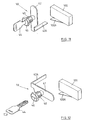
- FIG.1 is a schematic view of an embodiment of a desktop base for a portable computer according to the present invention. In the figure, a
base body 2 of adesktop base 1 for a portable computer comprises abase 3 and acover 4. Thebase body 2 has a supportingsection 6, and aguide 8 is provided to both sides of the supportingsection 6. Provided on the rear of the supportingsection 6 is aconnector 12, facing the front side, in the state where it is exposed. Provided on the front side of the supportingsection 6 is alock mechanism 14. Further, provided to thebase body 2 are apower switch 16 and akey mechanism 18. - FIG.2 shows a
portable computer 22 which is mounted on the supportingsection 6. Theportable computer 22 comprises asystem body 23 and acover 24. Provided in the back of thesystem body 23 is aconnector 26 in the state where it is or can be exposed. Thecover 24 is attached to the back side of thesystem body 23 so as to be capable of being opened. Aslider 27 for releasing a latch is provided in a position close to the front edge of thecover 24 so that, by operating theslider 27, an unillustrated latch mechanism for a cover can be released and a state that thecover 24 is latched to thesystem body 23 can be released. Further, provided to one side of thesystem body 23 is amooring convex piece 28. By making fast one end of a chain to themooring convex piece 28 and fixing the other end of the chain to an appropriate place, it is possible to prevent thecomputer 22 from being freely taken away. Although themooring convex piece 28 is drawn out from thesystem body 23 in FIG.2, the mooringconvex piece 28 may be constructed so as to be housed in thesystem body 23. - FIG.3 shows a state that the
computer 22 is being docked to or detached from thedesktop base 1. While being guided between bothguides 8, thecomputer 22 is placed on the supportingsection 6 from the rear end of thecomputer 22 and slid on the supportingsection 6 toward theconnector 12. Thecover 24 may be closed or opened. The mooringconvex piece 28 is left drawn out from thesystem body 23. As shown in FIG.4, formed in an inner wall of one ofguides 8 is agroove 32. Themooring convex piece 28 is intended to be inserted into thegroove 32. - FIG.5 shows a state that the
computer 22 is mounted on thedesktop base 1. In the state, the connector 26 (FIG.2) of thecomputer 22 is connected to theconnector 12 of thedesktop base 1. Further, since thelock mechanism 14 described in detail later works, thecomputer 22 cannot be pulled out to the front side from thedesktop base 1. Since themooring convex piece 28 of thecomputer 22 is inserted into thegroove 32, thecomputer 22 cannot be also detached from thedesktop base 1 in such a manner as pulled upward. - FIG.6 and FIG.7 show the construction, seen from the back side, of the
desktop base 1. Provided to aback plate 3A of thebase 3 are amooring fitting 34 and a plurality ofscrews 36. Themooring fitting 34 is used to make fast thedesktop base 1 to an appropriate place by a chain or the like so that thedesktop base 1 cannot be freely taken away. Thescrews 36 are used to fix thebase 3 to thecover 4 and are intended to fit intonut sections 38 fixed to thecover 4. To detach thecover 4 from thebase 3, it is necessary to unfasten thescrews 36 from thenut sections 38. - FIG.8 and FIG.9 show the construction, seen from the back side, of the
desktop base 1 in the state where thecover 4 is removed. Mounted on thebase 3 is anelectronic apparatus 39 such as an external storage device. Such an electronic apparatus other than an external storage device as a communication device, and a power unit, etc. can be also mounted on thebase 3, though they are not shown in the figures. Formed in afront plate 3B of thebase 3 is a throughhole 40. Apropeller 42 of thekey mechanism 18 attached to thecover 4 is intended to be inserted into the throughhole 40. However, as shown in FIG.9, thepropeller 42 can be inserted into the throughhole 40 only when the position of thepropeller 42 accords with that of the throughhole 40. - As shown in FIG.8, when the position of the
propeller 42 accords with that of the throughhole 40, thepropeller 42 cannot be inserted into the throughhole 40. Since thekey mechanism 18 is fixed to thecover 4, as the state of FIG.8, when the position of thepropeller 42 accords with that of the throughhole 40, thecover 4 cannot be detached from thebase 3 even if thescrews 36 are unfastened. That is, theelectronic apparatus 39 cannot be detached from thebase body 2. - FIG.10 shows three possible key positions of the
key mechanism 18, and FIG.11 to FIG.13 show the constructions of thekey mechanism 18 each of which corresponds to any of the three key positions. As shown in FIG.11 to FIG.13, thekey mechanism 18 comprises a key 44, akey hole 46, acylinder 48, and thepropeller 42. The position of thepropeller 42 can be changed by rotating the key 44, and the position of thepropeller 42 and that of the key 44 are always the same. - In FIG.10, disposed around the
key hole 46 are marks 151, 152, and 153 for indicating that thekey mechanism 18 is in any of first, second, and third key positions. The transition between the second key position and the third key position is performed through the first position. FIG.11, FIG.12, and FIG.13 show the constructions of thekey mechanism 18 in the first, second, and third key positions, respectively. - In the first key position, as described later, not only the
computer 22 can be freely docked to or detached from thedesktop base 1, but also thecover 4 can be removed from the base 3 (see FIG.9). Further, thekey mechanism 18 is constructed so as to prevent the key 44 from being pulled out from thekey hole 46 in its first key position. By preventing the key 44 from being pulled out, an operator is warned that the first key position indicates the state where the security for thedesktop base 1 is not achieved. That is, if the key 44 is constructed to be pulled out, there is a possibility that an operator forgets that thedesktop base 1 remains in the state where the security for thedesktop base 1 is not achieved, pulls out the key 44, and leaves thedesktop base 1; therefore, such construction described above is intended to prevent such a situation. - In the second and third key positions, as described later, not only the
computer 22 cannot be freely docked to or detached from thedesktop base 1, but also thecover 4 cannot be removed from the base 3 (see FIG.8). Further, thekey mechanism 18 is constructed so as to enable the key 44 to be pulled out from thekey hole 46 in the second and third key positions. The difference between the second key position and the third key position is, as described later, in that the power of thedesktop base 1 can be freely turned on in the second key position while the power which is once turned off cannot be turned on in the third key position. As shown in FIG.13, in the third key position, aconvex piece 42A provided to one end of thepropeller 42 contacts aswitch terminal 100A of akeylock microswitch 100. - FIG.14 shows the
lock mechanism 14. Thelock mechanism 14 has astopper 50. Thestopper 50 is supported by avertical rail 51 so as to be able to freely move upward and downward. Thevertical rail 51 is fixed to afront wall 3A of thebase 3. Aspring 52 is attached to thevertical rail 51, and thestopper 50 is applied tensile force upward by thespring 52. When thestopper 50 is in a high position, the top section of thestopper 50 protrudes further above the supportingsection 6. When thestopper 50 is in a low position, the top section of thestopper 50 does not protrude further above the supportingsection 6. Further, aconvex piece 53 for a latch is downward provided to thestopper 50, and alatch mechanism 54 is provided below theconvex piece 53 for a latch. Theconvex piece 53 for a latch and thelatch mechanism 54 work as follows: once pushed down, thestopper 50 is latched by thelatch mechanism 54 and remains pushed down even if it is released; when pushed down again, thestopper 50 is raised by thespring 52 since thelatch mechanism 54 releases thestopper 50 from the state where it is latched. Since the construction itself of thelatch mechanism 54 described above is well known, further description is omitted. - In FIG.14, the
lock mechanism 14 has an interlockingbody 55. The interlockingbody 55 is disposed between thepropeller 42 and thestopper 50 so that thestopper 50 can be influenced by a motion (position) of thepropeller 42 of thekey mechanism 18. The interlockingbody 55 is supported to thefront wall 3B of thebase 3 by an unillustrated guide member so as to be able to freely move horizontally. The interlockingbody 55 is applied tensile force by aspring 56 so as to go away from thestopper 50, that is, go to thepropeller 42. An engagingconvex section 57 is formed in the interlockingbody 55, and an engagingconcave section 58 is formed in thestopper 50. According to the position of the interlockingbody 55, the engagingconvex section 57 may or may not engage with the engagingconcave section 58. - When the
propeller 42 of thekey mechanism 18 is aligned with a vertical direction (FIG.11 and FIG.14), the interlockingbody 55 is moved to a predetermined position close to the left of thekey mechanism 18 by thespring 56 and the engagingconvex section 57 is away from the engagingconcave section 58. Therefore, thestopper 50 is capable of moving upward and downward. Further, when thepropeller 42 of thekey mechanism 18 is aligned with a horizontal direction (FIG.12 and FIG.13), the interlockingbody 55 is pushed by the tip section of thepropeller 42 and moved to a predetermined position close to thestopper 50 against thespring 56. In this case, if thestopper 50 is in the state where it is pushed down, the engagingconvex section 57 is engaged with the engagingconcave section 58 and thestopper 50 is locked in the state where it is pushed down. Further, if thestopper 50 is in the state where it is pushed up, since the engagingconvex section 57 is located under the bottom edge of thestopper 50 and prevents thestopper 50 from being pushed down, thestopper 50 is locked in the state where it is pushed up. - FIG.15 shows a
power supply 60 in thedesktop base 1. Supplied to thepower supply 60 is a predetermined ac voltage, for example, AC 100V orAC 120V from anAC inlet 62. Thepower supply 60 includes not only amain power circuit 70, but also asubpower circuit 80. Themain power circuit 70 and thesubpower circuit 80 are used to change ac voltage to a predetermined dc voltage, for example, DC 5V. Thesubpower circuit 80 may be, for example, one for charging a battery for theportable computer 22, and an existing apparatus can be easily utilized as thesubpower circuit 80 even if a particular apparatus is not provided. When theconnector 26 of theportable computer 22 is correctly connected to theconnector 12 of thedesktop base 1, a signal, that is, a "+DOCKED" signal indicating that thecomputer 22 is docked, is inputted to themain power circuit 70 and thesubpower circuit 80. "+DOCKED=1" is needed so as to enable themain power circuit 70 and thesubpower circuit 80. Thesubpower circuit 80 is immediately enabled by detecting "+DOCKED=1", while themain power circuit 70 is not enabled until it is detected that a "+POWER ON" signal from apower control circuit 90 is "1", in addition to detecting "+DOCKED=1". - A DC output of the
main power circuit 70, which is, for example, +DC5V, is provided to thecomputer 22 and aload 82 in thedesktop base 1. A DC output of thesubpower circuit 80, which is, for example, +DC5V, is provided to thepower control circuit 90. Thepower control circuit 90 comprises a NORcircuit 92 and an ANDcircuit 94. Inputted to one input of the NORcircuit 92 is a "+POWER GOOD" signal from themain power circuit 70. When themain power circuit 70 is enabled, "+POWER GOOD=1" is generated. Inputted to the other input of the NORcircuit 92 is a "+POWER ON OK" signal from thekeylock microswitch 100. When the operating terminal of thekeylock microswitch 100 is operated, "+POWER ON OK=0" is generated. The operating terminal of thekeylock microswitch 100 is operated, as shown in FIG.13, when thekey mechanism 18 is in the third key position and "+POWER ON OK=0" is generated. As shown in FIG.11 and FIG.12, when thekey mechanism 18 is in the first or second key position, thekeylock microswitch 100 is not operated and "+POWER ON OK=1" is generated. - The output of the NOR
circuit 92 is inputted to one input of the ANDcircuit 94. Provided to two inputs of the ANDcircuit 94 are inverters. Inputted to the other input of the ANDcircuit 94 is a "-POWER SW ON" signal from thepower switch 16. When thepower switch 16 is turned on, "-POWER SW ON=0" is generated. The ANDcircuit 94 outputs a "+POWER ON" signal. The "+POWER ON" signal is inputted to themain power circuit 70 through adelay circuit 96. - The
power control circuit 90 is further described. In the state where themain power circuit 70 is already enabled, "+POWER GOOD=l" is outputted. In the state, even if "+POWER ON OK=1" becomes "+POWER ON OK=0" by operating thekey mechanism 18 from the first or second key position to the third key position, the output of the NORcircuit 92 is not changed. Accordingly, the output of the ANDcircuit 94 is not changed as well. That is, in the state where themain power circuit 70 is already enabled, even if thekey mechanism 18 is operated from the first or second key position to the third key position, themain power circuit 70 is not turned off. - When the
main power circuit 70 is once turned off, "+POWER GOOD=0" is outputted. In the state, when thekey mechanism 18 is set to the third key position and "+POWER ON OK=0" is inputted, the output of the ANDcircuit 94, that is, "+POWER ON" always becomes "0". That is, after themain power circuit 70 is once turned off, it becomes impossible to enable themain power circuit 70 by operating thekey mechanism 18 to the third key position, even if thepower switch 16 is turned on. - Then, a role of the
delay circuit 96 is described. Thedelay circuit 96 is intended to prevent themain power circuit 70 from being incorrectly enabled in a transition period during which thesubpower circuit 80 completely is enabled after it detects "+DOCKED=1", that is, a period of time when the output of thepower control circuit 90 is unstable. By providing thedelay circuit 96, it is possible to prevent themain power circuit 70 from being raised, for example, in any of the following cases: - (1) the
AC inlet 62 is connected to an AC power outlet when thekey mechanism 18 is in the third key position, or theportable computer 22 is docked to thedesktop base 1, in the state where thepower switch 16 is turned on, when thekey mechanism 18 is in the third key position; and - (2) the
power switch 16 is turned on and theAC inlet 62 is connected to an AC power outlet in the state where theportable computer 22 is docked with thedesktop base 1. - In the following, operations of this embodiment is described in detail by reference to FIG.16 to FIG.20 as well. FIG.16 shows a state that the
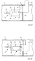
key mechanism 18 is in the first key position. In the state, thepropeller 42 is aligned with a vertical direction, the interlockingbody 55 is located most closely to thekey mechanism 18 within a predetermined range of its movement, and thestopper 50 is released from the interlockingbody 55 and is capable of freely moving upward and downward. To dock theportable computer 22 to thedesktop base 1, thestopper 50 should be pushed downward so that thelatch mechanism 54 can work. When thestopper 50 is pushed downward again after theportable computer 22 is docked with thedesktop base 1, thelatch mechanism 54 releases thestopper 50, and thestopper 50 is raised by the tensile force of thespring 52. To stabilize the state where theportable computer 22 is docked with thedesktop base 1, it is preferable that thestopper 50 should be raised. Thus, in the first key position, theportable computer 22 can be freely docked to and detached from thedesktop base 1. - Further, in the first key position, the
main power circuit 70 can be freely turned on by operating thepower switch 16, and thecover 4 can be freely detached from thebase 3. That is, in the first key position, there is no limit to physical access and electric access to theinternal storage device 39. In the first key position, the key 44 cannot be pulled out from thekey hole 46. - FIG.17 shows a state that the
stopper 50 is pulled out and thekey mechanism 18 is in the second key position. In the state, thepropeller 42 is aligned with a horizontal direction, the interlockingbody 55 is located most closely to thestopper 50 within the predetermined range of its movement, and the engagingconvex section 57 of the interlockingbody 55 is located under the lower end of thestopper 50 so as to prevent the interlockingbody 55 from moving. If theportable computer 22 is docked with thedesktop base 1, theportable computer 22 cannot be detached from thedesktop base 1. In the second key position, themain power circuit 70 can be freely turned on by operating thepower switch 16, but thecover 4 cannot be detached from thebase 3. Further, in the second key position, the key 44 can be pulled out from thekey hole 46. - FIG.18 shows a state that the
stopper 50 is pushed in and thekey mechanism 18 is in the second key position. In the state, thepropeller 42 is aligned with a horizontal direction, the interlockingbody 55 is located most closely to thestopper 50 within the predetermined range of its movement, and the engagingconvex section 57 of the interlockingbody 55 is engaged with the engagingconcave section 58 of thestopper 50 so as to prevent the interlockingbody 55 from moving. If theportable computer 22 is not docked with thedesktop base 1, theportable computer 22 can be freely docked to thedesktop base 1. Further, in the second key position, thedesktop base 1 can be freely utilized since themain power circuit 70 can be freely turned on by operating thepower switch 16, but thecover 4 cannot be detached from thebase 3. The key 44 can be pulled out from thekey hole 46. - FIG.19 shows a state that the
stopper 50 is pulled out and thekey mechanism 18 is in the third key position. In the state, thepropeller 42 is aligned with a horizontal direction, the interlockingbody 55 is located most closely to thestopper 50 within the predetermined range of its movement, and the engagingconvex section 57 of the interlockingbody 55 is located under the lower end of thestopper 50 so as to prevent the interlockingbody 55 from moving. If theportable computer 22 is docked with thedesktop base 1, theportable computer 22 cannot be detached from thedesktop base 1. In the third key position, even if thepower switch 16 is turned on, themain power circuit 70 cannot be enabled. However, even if thekey mechanism 18 is incorrectly set to the third key position when themain power circuit 70 is already in an ON state, power supply does not fall. Therefore, user data is not lost due to a key maloperation. Thecover 4 cannot be detached from thebase 3. The key 44 can be pulled out from thekey hole 46. - FIG.20 shows a state that the
stopper 50 is pushed in and thekey mechanism 18 is in the third key position. In the state, thepropeller 42 is aligned with a horizontal direction, the interlockingbody 55 is located most closely to thestopper 50 within the predetermined range of its movement, and the engagingconvex section 57 of the interlockingbody 55 is engaged with the engagingconcave section 58 of thestopper 50 so as to prevent the interlockingbody 55 from moving. If theportable computer 22 is not docked with thedesktop base 1, theportable computer 22 can be freely docked to thedesktop base 1, but themain power circuit 70 cannot be enabled even if thepower switch 16 is turned on. - Therefore, even if the
portable computer 22 is freely docked to thedesktop base 1, theelectronic equipment 39 in thedesktop base 1 cannot be accessed. Further, thecover 4 cannot be detached from thebase 3. The key 44 can be pulled out from thekey hole 46.KEY POSITION DETACH COVER ATTACH OR DETACH COMPUTER POWER SWITCH ON VALID OR INVALID PULL OUT KEY FIRST KEY POSITION POSSIBLE POSSIBLE VALID IMPOSSIBLE SECOND KEY POSITION LOCKED WITH STOPPER PULLED OUT IMPOSSIBLE IMPOSSIBLE VALID POSSIBLE LOCKED WITH STOPPER HOUSED POSSIBLE POSSIBLE VALID POSSIBLE THIRD POSITION LOCKED WITH STOPPER PULLED OUT IMPOSSIBLE IMPOSSIBLE INVALID POSSIBLE LOCKED WITH STOPPER HOUSED POSSIBLE POSSIBLE INVALID POSSIBLE Table 1 - Table 1 summarizes, with respect to each of the first to the third key positions, whether or not the
body cover 4 can be detached, whether or not theportable computer 22 can be docked to and detached from thedesktop base 1, whether or not an on off operation of the power switch is valid, and whether or not the key 44 can be pulled out. - According to such an embodiment as described above, it is possible to sufficiently take a security measure to the internal
electronic apparatus 39 such as a storage device whether theportable computer 22 is docked or not. Further, it is also possible to restrict the physical access to theelectronic apparatus 39 even if thecomputer 22 is allowed to be freely docked to and detached from thedesktop base 1. - Besides, though the
desktop base 1, in said embodiment, is what is called an expanded function unit or an expansion box having an internal electronic apparatus for working in cooperation with thecomputer 22, it will be appreciated that the present invention may be applied not only to an expanded function unit etc., but also to a power supply which only supplies an electrical power, or to a connector unit having various connectors with or without power supply. Or, the present invention may be applied to a simple desktop base to which neither power is supplied nor a connector is provided. Further, a top board may be attached to a desktop base so as to become a supporting board of a CRT. Still further, instead of thegroove 32 and the mooringconvex piece 28 of said embodiment, a channel may be formed in both sides of a computer, and a convex section which is inserted into said channel so as to control the detachment of the computer may be formed in a desktop base.
Claims (6)
- Docking apparatus for a portable computer having; a body for supporting the portable computer (6);
a connector (12) for electrically connecting to said portable computer;
an electronic apparatus (39) provided in said body for connecting to an electronic circuit in said portable computer through said connector (12) and for working in cooperation with said electronic circuit;
a power supply (60) for supplying power to said electronic apparatus; a power switch (16) for turning on or off said power supply (60);
and a key mechanism (14) for locking said electronic apparatus in the condition under which said electronic apparatus is prevented from being detached from said body. - Docking apparatus for a portable computer as claimed in claim 1,
wherein said body has a base (3) on which said electronic apparatus is mounted and a cover (4) which is installed on said base so as to cover said electronic apparatus,
said cover being constructed so as to be locked by said key mechanism in the condition under which said cover cannot be detached from said base. - Docking apparatus for a portable computer having;
a body for supporting the portable computer (6);
a connector (12), provided to said body for electrically connecting to said portable computer;
an electronic apparatus (39) provided in said body for connecting to an electronic circuit in said portable computer through said connector and for working in cooperation with said electronic circuit;
a power supply (60) for supplying power to said electronic apparatus;
a power switch (16) for turning on or off said power supply;
a power controller (90) which can be operated so as not to turn on said power supply (60) even if said power switch (16) is turned on;
and a key mechanism (14) for locking said power supply in the condition under which said power controller is operated so as not to turn on said power supply even if said power switch is turned on. - Docking apparatus for a portable computer as claimed in claim 3,
wherein said key mechanism (14) can be operated so as to lock said electronic apparatus in the condition under which said electronic apparatus is prevented from being detached from said body. - Docking apparatus for a portable computer having;
a body for supporting the portable computer (16);
a connector (12) provided to said body for electrically connecting to said portable computer;
an electronic apparatus (39) provided in said body for connecting to an electronic circuit in said portable computer through said connector and for working in cooperation with said electronic circuit;
a power supply (60) for supplying power to said electronic apparatus;
a power switch (16) for turning on or off said power supply;
a power controller (90) which can be operated so as not to turn on said power supply even if said power switch is turned on;
a lock mechanism having two states, a lock state where a portable computer supported by said body is prevented from being detached from said body and an unlock state where a portable computer supported by said body can be detached from said body;
and a key mechanism having a first key position in which said electronic apparatus can be detached from said body, and in which said lock mechanism is in said unlock statea second key position in which said power supply can be turned on when said power switch is turned on without bringing said power controller into operation and which said lock mechanism is in said lock state and a third key position in which said power supply is presented from being turned on by said power controller even if said power switch is turned on and in which said lock mechanism is in the lock state. - Docking apparatus for a portable computer as claimed in claim 5,
wherein said power controller is constructed so that said power supply will continue to be in an ON state if said power supply is already in the ON state before said key mechanism is operated to be in said third key position, and so that said power supply will not be in the ON state in spite of a power-on operation when said power switch is once turned off and then is turned on again.
Applications Claiming Priority (3)
| Application Number | Priority Date | Filing Date | Title |
|---|---|---|---|
| JP291028/92 | 1992-10-29 | ||
| JP4291028A JPH087646B2 (en) | 1992-10-29 | 1992-10-29 | Stationary device for portable computer |
| US08/141,770 US5450271A (en) | 1992-10-29 | 1993-10-22 | Portable computer docking apparatus including a key mechanism controlling a power supply and a locking mechanism |
Publications (1)
| Publication Number | Publication Date |
|---|---|
| EP0595554A1 true EP0595554A1 (en) | 1994-05-04 |
Family
ID=26558361
Family Applications (1)
| Application Number | Title | Priority Date | Filing Date |
|---|---|---|---|
| EP19930308409 Withdrawn EP0595554A1 (en) | 1992-10-29 | 1993-10-21 | Docking apparatus for portable computer |
Country Status (4)
| Country | Link |
|---|---|
| US (1) | US5450271A (en) |
| EP (1) | EP0595554A1 (en) |
| JP (1) | JPH087646B2 (en) |
| CA (1) | CA2105421C (en) |
Cited By (6)
| Publication number | Priority date | Publication date | Assignee | Title |
|---|---|---|---|---|
| DE4403712A1 (en) * | 1994-02-07 | 1995-11-02 | Bayerische Motoren Werke Ag | On-board computer for motor vehicles |
| DE19609635A1 (en) * | 1996-03-12 | 1997-09-18 | Siemens Nixdorf Inf Syst | Holder and transport device for portable note book computer which can be inserted into base personal computer or docking unit |
| EP0798622A2 (en) * | 1996-03-28 | 1997-10-01 | International Business Machines Corporation | Secure docking unit for a portable computer |
| EP0840197A2 (en) * | 1996-10-31 | 1998-05-06 | Hewlett-Packard Company | Physical security system for portable computer |
| CN1096634C (en) * | 1996-07-10 | 2002-12-18 | 三星电子株式会社 | Power supply apparatus for portable computer and DC input selection circuit adapted to the same |
| WO2008089320A2 (en) * | 2007-01-19 | 2008-07-24 | 55 Consultants, Inc. | Apparatus for improved security and connectivity of a computer display and other secured items |
Families Citing this family (63)
| Publication number | Priority date | Publication date | Assignee | Title |
|---|---|---|---|---|
| JP3360893B2 (en) * | 1993-09-30 | 2003-01-07 | 株式会社東芝 | Extension device for electronic equipment |
| US5477415A (en) * | 1993-11-12 | 1995-12-19 | Texas Instruments Incorporated | Automatic computer docking station having a motorized tray, cammed side connectors, motorized side connectors, and locking and unlocking guide pins |
| NL9400327A (en) * | 1994-03-03 | 1995-10-02 | Tulip Computers International | Device for securing a computer. |
| US5598537A (en) * | 1994-03-25 | 1997-01-28 | Advanced Micro Devices, Inc. | Apparatus and method for driving a bus to a docking safe state in a dockable computer system including a docking station and a portable computer |
| JPH0895669A (en) * | 1994-09-29 | 1996-04-12 | Toshiba Corp | Electronic equipment system |
| US5725194A (en) * | 1995-01-30 | 1998-03-10 | Ideal Ideas, Inc. | Computer component security device with top plate |
| US5645261A (en) * | 1995-01-30 | 1997-07-08 | Ideal Ideas, Inc. | Computer component security device |
| US5660451A (en) * | 1995-01-30 | 1997-08-26 | Ideal Ideas, Inc. | Computer component security device with parallel table securing means |
| US5673173A (en) * | 1995-03-01 | 1997-09-30 | Acer Incorporated | Portable computer having a modular power conversion unit |
| KR0157129B1 (en) * | 1995-03-28 | 1998-11-16 | 김광호 | Power control apparatus of docking station |
| KR0163879B1 (en) * | 1995-06-14 | 1998-12-15 | 김광호 | Locking device for docking station |
| JP3329637B2 (en) * | 1995-10-20 | 2002-09-30 | 株式会社東芝 | Expansion station for electronic equipment and electronic equipment system |
| US5838539A (en) * | 1995-11-08 | 1998-11-17 | Electronics Accessory Specialists International | Docking module for portable computers |
| US5595074A (en) * | 1996-01-29 | 1997-01-21 | Munro; Robert G. | Desktop security locking station for a laptop computer or similarly sized computer peripheral |
| US5664950A (en) * | 1996-02-13 | 1997-09-09 | Lawrence; Richard J. | Hardware mechanism for computer software security |
| US5692400A (en) * | 1996-03-25 | 1997-12-02 | Hewlett-Packard Company | Securing portable computers and associated docking systems |
| US5859762A (en) * | 1996-05-13 | 1999-01-12 | International Business Machines Corporation | Docking station for portable computers |
| US5911777A (en) * | 1996-07-05 | 1999-06-15 | Ncr Corporation | Method and apparatus for reporting unauthorized attempt to release a portable computer from a docking station |
| KR100190843B1 (en) * | 1996-07-31 | 1999-06-01 | 윤종용 | Locking device for a portable folding computer |
| KR100245200B1 (en) * | 1996-08-01 | 2000-02-15 | 윤종용 | A portable computer with a locking means |
| US5875094A (en) * | 1996-08-02 | 1999-02-23 | Compaq Computer Corporation | Portable computer docking station with adjustable insertion angle |
| US5826042A (en) * | 1996-08-02 | 1998-10-20 | Compaq Computer Corporation | Portable computer docking station with module connection replicator |
| US5761322A (en) * | 1996-12-31 | 1998-06-02 | Compaq Computer Corporation | Portable computer speaker enclosure |
| US5884049A (en) * | 1996-12-31 | 1999-03-16 | Compaq Computer Corporation | Increased processor performance comparable to a desktop computer from a docked portable computer |
| US5754397A (en) * | 1997-01-21 | 1998-05-19 | Dell Computer Corporation | Docking connector with height adjustment in a computer system |
| KR100422500B1 (en) * | 1997-03-25 | 2004-06-26 | 삼성전자주식회사 | Portable computer having power control mode converter |
| US6142593A (en) * | 1997-04-25 | 2000-11-07 | Samsung Electronics Co., Ltd. | Docking station with adjustable guide rails |
| US6366458B1 (en) | 1997-06-30 | 2002-04-02 | Sony Corporation | Docking unit for portable electronic device and locking method of docking unit |
| US5969939A (en) * | 1997-07-08 | 1999-10-19 | Dell Usa, L.P. | Computer with docking station for docking and cooling the computer |
| US5912621A (en) * | 1997-07-14 | 1999-06-15 | Digital Equipment Corporation | Cabinet security state detection |
| US6042414A (en) * | 1997-11-14 | 2000-03-28 | Intermec Ip Corp. | Vehicle dock for portable data collection terminal |
| US5995366A (en) * | 1998-01-16 | 1999-11-30 | Dell U.S.A., L.P. | Computer anti-theft system and method |
| US6189099B1 (en) | 1998-02-11 | 2001-02-13 | Durango Corporation | Notebook security system (NBS) |
| US6216230B1 (en) | 1998-02-11 | 2001-04-10 | Durango Corporation | Notebook security system (NBS) |
| US6049454A (en) * | 1998-04-15 | 2000-04-11 | Dell Computer Corporation | Computer monitor stand and docking method |
| KR20000008298A (en) * | 1998-07-11 | 2000-02-07 | 윤종용 | Portable computer |
| US6093039A (en) * | 1998-08-06 | 2000-07-25 | Mobility Electronics, Inc. | Docking device for a portable computer |
| US6151218A (en) * | 1998-08-21 | 2000-11-21 | Compaq Computer Corporation | Physical security system for portable computer/port replicator |
| JP3176345B2 (en) * | 1998-10-21 | 2001-06-18 | 米沢日本電気株式会社 | A mechanism for preventing the stopper of the port replicator releasing mechanism for a notebook personal computer from being disabled. |
| US6182481B1 (en) * | 1998-10-27 | 2001-02-06 | Neil Frank Nagy | Security lock for laptop and notebook computers |
| US6181552B1 (en) * | 1998-10-27 | 2001-01-30 | Robert J. Neville, Jr. | Computer assembly |
| US6061234A (en) * | 1999-03-15 | 2000-05-09 | Dell U.S.A., L.P. | Secured snap-on cover for a computer system docking station |
| US6324062B1 (en) * | 1999-04-02 | 2001-11-27 | Unisys Corporation | Modular packaging configuration and system and method of use for a computer system adapted for operating multiple operating systems in different partitions |
| US6189349B1 (en) * | 1999-05-28 | 2001-02-20 | Hewlett-Packard Company | Single retracting security hook of desktop port replicator providing security for dissimilar multiple portable computers |
| US6363763B1 (en) * | 1999-07-29 | 2002-04-02 | Arthur Geringer | Lock with sensor |
| US6590151B1 (en) * | 1999-10-04 | 2003-07-08 | Gateway, Inc. | Information handling system suitable for removable mounting |
| US6418013B1 (en) * | 1999-12-06 | 2002-07-09 | Dell Products Inc. | System and method for one touch operation of a docking station |
| TW468713U (en) * | 2000-10-17 | 2001-12-11 | Sinox Co Ltd | Locking device for mini computer |
| US6577501B2 (en) * | 2001-04-30 | 2003-06-10 | Macase Industrial Group Ga., Inc. | Removable power pack supply for computer cabinet |
| US7490250B2 (en) * | 2001-10-26 | 2009-02-10 | Lenovo (Singapore) Pte Ltd. | Method and system for detecting a tamper event in a trusted computing environment |
| US6687121B1 (en) * | 2002-11-27 | 2004-02-03 | Mitac Technology Corp. | Switch protection apparatus |
| TWM249078U (en) * | 2003-12-10 | 2004-11-01 | Wistron Corp | Joint seat with transmission mechanism for releasing the mutual locking with external device |
| US7333325B2 (en) * | 2004-10-14 | 2008-02-19 | Hewlett-Packard Development Company, L.P. | Battery for dockable electronic device |
| US7227747B2 (en) * | 2004-10-20 | 2007-06-05 | Hewlett-Packard Development Company, L.P. | Securing computer equipment |
| US8496213B1 (en) * | 2005-04-08 | 2013-07-30 | Mobile Oasis LLC | System and apparatus for mobile information handling |
| US20060254330A1 (en) * | 2005-04-08 | 2006-11-16 | Security Door Controls | Lock with latch sensor |
| JP4761033B2 (en) * | 2005-08-11 | 2011-08-31 | 横河電機株式会社 | Paperless recorder |
| JP2009026234A (en) * | 2007-07-23 | 2009-02-05 | Fujitsu Ltd | Function expansion device and electronic device system |
| CA2656431C (en) | 2008-02-27 | 2015-04-14 | L&P Property Management Company | Computer docking station for a vehicle |
| TWI373170B (en) * | 2009-03-16 | 2012-09-21 | Asustek Comp Inc | Adapter and portable electronic apparatus |
| JP2014074277A (en) * | 2012-10-03 | 2014-04-24 | Funai Electric Co Ltd | Cylinder lock, electronic apparatus, and register |
| US9429993B2 (en) * | 2013-11-21 | 2016-08-30 | Toshiba Global Commerce Solutions Holdings Corporation | Computing device docking systems |
| US10745940B2 (en) * | 2018-05-21 | 2020-08-18 | Aristocrat Technologies Australia Pty Limited | Universal switch assembly for locking and unlocking an access door of a gaming machine cabinet |
Citations (3)
| Publication number | Priority date | Publication date | Assignee | Title |
|---|---|---|---|---|
| GB2154651A (en) * | 1984-02-17 | 1985-09-11 | Shorrock Security Systems Ltd | Key-operated security mechanism |
| EP0354476A2 (en) * | 1988-08-08 | 1990-02-14 | Siemens Nixdorf Informationssysteme Aktiengesellschaft | Locking device for computer apparatus |
| US5126954A (en) * | 1990-04-18 | 1992-06-30 | Sotec Company, Limited | Function expansion station for a portable computer |
Family Cites Families (6)
| Publication number | Priority date | Publication date | Assignee | Title |
|---|---|---|---|---|
| JPS6142618U (en) * | 1984-08-13 | 1986-03-19 | カシオ計算機株式会社 | Connection structure of electronic equipment |
| JPH0359709A (en) * | 1989-07-28 | 1991-03-14 | Seiko Epson Corp | Locking mechanism for electronic information apparatus |
| US5159533A (en) * | 1991-05-07 | 1992-10-27 | Kuang Ma H | Portable note-book computer expansion device with disk drives |
| US5154456A (en) * | 1991-06-27 | 1992-10-13 | Compaq Computer Corporation | Security locking bracket apparatus for a portable computer |
| US5164886A (en) * | 1991-12-17 | 1992-11-17 | Chang Lien Sheng | Computer mainframe housing assembled with hooks and notches |
| US5311397A (en) * | 1992-08-06 | 1994-05-10 | Logistics Management Inc. | Computer with modules readily replaceable by unskilled personnel |
-
1992
- 1992-10-29 JP JP4291028A patent/JPH087646B2/en not_active Expired - Lifetime
-
1993
- 1993-10-21 EP EP19930308409 patent/EP0595554A1/en not_active Withdrawn
- 1993-10-22 CA CA 2105421 patent/CA2105421C/en not_active Expired - Fee Related
- 1993-10-22 US US08/141,770 patent/US5450271A/en not_active Expired - Fee Related
Patent Citations (3)
| Publication number | Priority date | Publication date | Assignee | Title |
|---|---|---|---|---|
| GB2154651A (en) * | 1984-02-17 | 1985-09-11 | Shorrock Security Systems Ltd | Key-operated security mechanism |
| EP0354476A2 (en) * | 1988-08-08 | 1990-02-14 | Siemens Nixdorf Informationssysteme Aktiengesellschaft | Locking device for computer apparatus |
| US5126954A (en) * | 1990-04-18 | 1992-06-30 | Sotec Company, Limited | Function expansion station for a portable computer |
Cited By (11)
| Publication number | Priority date | Publication date | Assignee | Title |
|---|---|---|---|---|
| DE4403712A1 (en) * | 1994-02-07 | 1995-11-02 | Bayerische Motoren Werke Ag | On-board computer for motor vehicles |
| DE4403712B4 (en) * | 1994-02-07 | 2005-04-21 | Bayerische Motoren Werke Ag | On-board computer for motor vehicles |
| DE19609635A1 (en) * | 1996-03-12 | 1997-09-18 | Siemens Nixdorf Inf Syst | Holder and transport device for portable note book computer which can be inserted into base personal computer or docking unit |
| DE19609635C2 (en) * | 1996-03-12 | 1998-02-19 | Siemens Nixdorf Inf Syst | Basic computer unit with a holding and transport device for a notebook computer unit |
| EP0798622A2 (en) * | 1996-03-28 | 1997-10-01 | International Business Machines Corporation | Secure docking unit for a portable computer |
| EP0798622A3 (en) * | 1996-03-28 | 1999-07-28 | International Business Machines Corporation | Secure docking unit for a portable computer |
| CN1096634C (en) * | 1996-07-10 | 2002-12-18 | 三星电子株式会社 | Power supply apparatus for portable computer and DC input selection circuit adapted to the same |
| EP0840197A2 (en) * | 1996-10-31 | 1998-05-06 | Hewlett-Packard Company | Physical security system for portable computer |
| EP0840197A3 (en) * | 1996-10-31 | 2000-04-19 | Hewlett-Packard Company | Physical security system for portable computer |
| WO2008089320A2 (en) * | 2007-01-19 | 2008-07-24 | 55 Consultants, Inc. | Apparatus for improved security and connectivity of a computer display and other secured items |
| WO2008089320A3 (en) * | 2007-01-19 | 2008-09-18 | 55 Consultants Inc | Apparatus for improved security and connectivity of a computer display and other secured items |
Also Published As
| Publication number | Publication date |
|---|---|
| CA2105421A1 (en) | 1994-04-30 |
| CA2105421C (en) | 1997-06-24 |
| US5450271A (en) | 1995-09-12 |
| JPH087646B2 (en) | 1996-01-29 |
| JPH06149409A (en) | 1994-05-27 |
Similar Documents
| Publication | Publication Date | Title |
|---|---|---|
| EP0595554A1 (en) | Docking apparatus for portable computer | |
| US6046571A (en) | Port replicator with secure integral battery charging cradle | |
| US6151218A (en) | Physical security system for portable computer/port replicator | |
| US6424524B2 (en) | Wedge-shaped port replicator for portable computer | |
| US5175671A (en) | Expanding apparatus for portable electronic apparatus | |
| US4941841A (en) | Adapter and a removable slide-in cartridge for an information storage system | |
| USRE34369E (en) | Adapter and a removable slide-in cartridge for an information storage system | |
| US6522532B2 (en) | Cable docking system and method for a computer | |
| US5995366A (en) | Computer anti-theft system and method | |
| EP0441400B1 (en) | Electronic system comprising an expansion device for expanding functions of compact electronic apparatus | |
| US6674637B2 (en) | Portable computer equipped with add-on battery | |
| US6331934B1 (en) | Computer docking station with anti-theft locking mechanisms for removable components | |
| US5020926A (en) | Printer mounting arrangement | |
| US5388032A (en) | Computer equipment monitor and discriminator | |
| EP0664900B1 (en) | Portable computer and docking station | |
| EP0481461B1 (en) | Function expansion unit capable of supplying power to computer | |
| KR970001366B1 (en) | Cable-managing device for computer | |
| US6072695A (en) | Horizontal loading docking station with uninterrupted power supply | |
| AU672476B2 (en) | Portable electronic computer with removable disk drive | |
| US5745340A (en) | Separable display of computer generated information | |
| US6580603B1 (en) | Structure for mounting computer devices, pivotable between operating and service positions, including a pivoting support member | |
| US6169655B1 (en) | Computer docking drawer | |
| WO2014120171A1 (en) | Display mounting system | |
| US5169332A (en) | Means for locking cables and connector ports | |
| US5142446A (en) | Apparatus for securely attaching and detaching portable computer terminals to portable optional devices |
Legal Events
| Date | Code | Title | Description |
|---|---|---|---|
| PUAI | Public reference made under article 153(3) epc to a published international application that has entered the european phase |
Free format text: ORIGINAL CODE: 0009012 |
|
| AK | Designated contracting states |
Kind code of ref document: A1 Designated state(s): DE FR GB |
|
| 17P | Request for examination filed |
Effective date: 19940819 |
|
| STAA | Information on the status of an ep patent application or granted ep patent |
Free format text: STATUS: THE APPLICATION HAS BEEN WITHDRAWN |
|
| 18W | Application withdrawn |
Withdrawal date: 19971121 |