EP0595513B1 - Negative pressure air bearing slider - Google Patents
Negative pressure air bearing slider Download PDFInfo
- Publication number
- EP0595513B1 EP0595513B1 EP93308245A EP93308245A EP0595513B1 EP 0595513 B1 EP0595513 B1 EP 0595513B1 EP 93308245 A EP93308245 A EP 93308245A EP 93308245 A EP93308245 A EP 93308245A EP 0595513 B1 EP0595513 B1 EP 0595513B1
- Authority
- EP
- European Patent Office
- Prior art keywords
- slider
- rail
- air bearing
- rails
- trailing edge
- Prior art date
- Legal status (The legal status is an assumption and is not a legal conclusion. Google has not performed a legal analysis and makes no representation as to the accuracy of the status listed.)
- Expired - Lifetime
Links
Images


Classifications
-
- G—PHYSICS
- G11—INFORMATION STORAGE
- G11B—INFORMATION STORAGE BASED ON RELATIVE MOVEMENT BETWEEN RECORD CARRIER AND TRANSDUCER
- G11B5/00—Recording by magnetisation or demagnetisation of a record carrier; Reproducing by magnetic means; Record carriers therefor
- G11B5/48—Disposition or mounting of heads or head supports relative to record carriers ; arrangements of heads, e.g. for scanning the record carrier to increase the relative speed
- G11B5/58—Disposition or mounting of heads or head supports relative to record carriers ; arrangements of heads, e.g. for scanning the record carrier to increase the relative speed with provision for moving the head for the purpose of maintaining alignment of the head relative to the record carrier during transducing operation, e.g. to compensate for surface irregularities of the latter or for track following
- G11B5/60—Fluid-dynamic spacing of heads from record-carriers
- G11B5/6005—Specially adapted for spacing from a rotating disc using a fluid cushion
-
- G—PHYSICS
- G11—INFORMATION STORAGE
- G11B—INFORMATION STORAGE BASED ON RELATIVE MOVEMENT BETWEEN RECORD CARRIER AND TRANSDUCER
- G11B21/00—Head arrangements not specific to the method of recording or reproducing
- G11B21/16—Supporting the heads; Supporting the sockets for plug-in heads
- G11B21/20—Supporting the heads; Supporting the sockets for plug-in heads while the head is in operative position but stationary or permitting minor movements to follow irregularities in surface of record carrier
- G11B21/21—Supporting the heads; Supporting the sockets for plug-in heads while the head is in operative position but stationary or permitting minor movements to follow irregularities in surface of record carrier with provision for maintaining desired spacing of head from record carrier, e.g. fluid-dynamic spacing, slider
Definitions
- This invention relates generally to computer data storage drives and more specifically to a negative air pressure air bearing slider structure employed in conjunction with data storage drives.
- the negative pressure air bearing slider designs of the prior art are generally preferable to conventional flat taper slider configurations.
- the negative pressure structure enables the utilization of low suspension preloads, yielding decreased stationary frictional forces. These forces are often referred to as "stictional" forces. Negative pressure structures also offer the potential for improved stop/start performance.
- a further object of the invention is to provide an air bearing structure having improved static and dynamic performance over existing structures.
- an air bearing slider for supporting a transducer in relation to a movable storage medium, said air bearing slider comprising:
- the air bearing slider of the present invention provides a structure which optimizes the amount of negative pressure provided by the slider structure.
- This slider is employed in conjunction with a data storage medium which may be engaged in motion relative to the slider.
- the slider structure includes a leading edge and a trailing edge, the edges being determined with reference to the motion of the data storage medium.
- the slider also includes a bottom surface which faces the data storage medium. The bottom surface extends between the leading edge and the trailing edge.
- the negative pressure contours of the slider can, in one embodiment, be determined by means of a U-shaped rail situated between two outer taper-flat pads on the bottom surface. The amount of negative pressure is controlled by adjusting the length and width of the area enclosed by the U-shaped rail.
- the two outer taper-flat pads provide roll stiffness. These pads may be extended to the trailing edge of the slider to provide a mounting location for a read/write element. In this manner, the negative pressure contours may be optimized for specific device applications.
- a second embodiment of the invention includes an isolated island positioned between the legs of a U-shaped rail.
- the purpose of the island is to provide means for mounting a read/write element to the slider.
- Two outer pads are employed for improving the roll stiffness characteristics of the slider. These pads may be offset from the trailing edge toward the leading edge of the slider to eliminate roll sensitivity.
- a third embodiment of the invention includes element mounting means in the form of a center rail extending from the U-shaped rail to the trailing edge of the slider structure.
- Two outer pads are employed, which may be offset from the trailing edge toward the leading edge of the slider to eliminate roll sensitivity.
- the U-shaped rail can be situated at a position on the bottom surface between the leading and trailing edges of the slider structure. Centering the U-shaped rail between the lateral edges of the slider provides enhanced pitch angle and fly height design flexibility.
- two U-shaped rails are spaced laterally on the bottom surface near the slider leading edge.
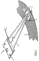
- Fig. 1 is a perspective view illustrating means for employing a slider according to a preferred embodiment of the present invention in a direct access storage device (DASD).
- the preferred embodiment of the invention concerns a slider 10 which is supported in a DASD with respect to a disk surface 12 by a slider suspension assembly 14 which includes a mount plate 16 and load beam 18.
- the slider 10 is attached to the load beam 18 by means of a flexure 19.
- a data read/write transducer 20 is mounted on the slider 10.
- One or more leads 21 connect the transducer 20 to DASD electronics.
- Fig. 2 is a block diagram illustrating the essential complement of functional components in a DASD employing the slider design of a preferred embodiment of this invention.
- Fig. 2 illustrates a single-disk device, it is to be understood that this is not intended to limit the practice of the invention to such devices. In fact, the invention is equally applicable to DASD's with multiple disks.
- the disk 30 is mounted on a rotatable spindle 32 that is rotated by a drive motor 33.
- the disk 30 has an upper surface 34 and a lower surface 35.
- a slider 38 with a transducer mounted thereon faces the upper surface 34.
- Another slider 40 with a transducer mounted thereon faces the lower surface 35.
- the sliders 38 and 40 are positioned with respect to these surfaces 34 and 35 by respective movable slider arm assemblies 45 and 46.
- the arm assemblies are conventionally mounted to an actuator 42.
- the transducers on the sliders 38 and 40 are connected to conventional data channel electronics.
- read/write channel electronics 48 are shown only for the slider 38, it being understood that the transducer on the slider 40 is similarly supported in the DASD.
- a control unit 50 typically in the form of a processor, provides position control signals on a signal path 52 to the actuator 42. These signals control the positions of the slider 38 and 40 with respect to the surfaces of the disk 30.
- the control unit 50 provides motor speed control signals to control the rotational speed of the drive motor 33.
- the control unit 50 also processes read and write signals for the transducer on the slider 38 by way of the read/write channel electronics 48.
- Each slider 38 and 40 may support one or more read/write transducers. As the disk 30 rotates, the sliders 38 and 40 are moved radially in and out over their respective disk surfaces so that the read/write transducers may access different portions of the disk 30 where desired data is recorded. Each slider 38 and 40 is attached to its respective actuator arm 45 and 46 by means of a suspension mechanism.
- the flying height of a slider is the distance between a particular point on a slider and the disk surface when the slider is supported on its cushion of air.
- the slider point coincides with a transducer location; usually, this location is at the trailing edge of the slider.
- spacing and “slider spacing” when used in the description and drawings are synonymous with flying height.
- Figs. 3A and 3B illustrate bottom plan and rear elevation views, respectively, of a U-shaped rail air bearing slider structure 100.
- the slider structure 100 is designed to be used in a data storage device having a storage medium engaged in motion relative to the slider during data read/write operations.
- the slider structure includes a bottom surface 101 which, in the industrial environment, is positioned adjacent to and facing the data storage medium.
- the U-shaped rail 102 extends outwardly from the bottom surface 101 and is positioned between two outer taper-flat rails 104 and 105.
- the rails 104 and 105 include respective forward tapers 106 and 107.
- the slider structure 100 has a leading edge 110, a trailing edge 111, and respective side edges 112 and 113.
- the U-shaped rail 102 includes a cross rail portion 114 which transitions to a forward tapered section 115. As shown in Fig. 3A, the cross rail portion 114 extends laterally across less than the full width of the slider structure 100 between the side rails 104 and 105.
- the U-shaped rail 102 also includes a pair of side rails 116 and 117 which are substantially parallel with the forward sections of the side rails 104 and 105 and which join the cross rail portion 114 to form a three-sided enclosure enclosing an area 118 on the slider bottom surface 101.
- a negative pressure is generated in the area 118 enclosed on three sides by the U-shaped rail 102.
- the amount of negative air pressure generated by the slider structure 100 is controlled by the length and width of the area 118.
- the two outer taper-flat rails 104 and 105 are each situated substantially adjacent to a respective side edge. These rails provide roll stiffness and may be extended to the rear surface 108 to provide a mounting location for read/write transducers. As Fig. 3A illustrates, the rails 104 and 105 have substantially constant widths from the leading edge 110 to the tips of the rails 116 and 117. From there to the trailing edge 111, the widths of the pads 104 and 105 increase constantly.
- the U-shaped rail is formed on the bottom surface of the slider at a location which is centered between, but separated from the side rails. This structure characterizes the first through the fourth embodiments of the invention.
- Figs. 4A and 4B are bottom plan and rear elevation views, respectively, of a U-shaped rail air bearing slider structure 200.
- the slider structure 200 corresponds essentially to the slider structure 100 of Figs. 3A and 3B in having a U-shaped rail 202 with a forward taper 203 that extends outwardly from the bottom surface 201 and is centered laterally between two outer taper-flat rails 204 and 205 with forward tapers 206 and 207, respectively.
- the taper-flat rails 204 and 205 in Fig. 4A exhibit a continuous width.
- outer taper-flat rails 204 and 205 do not extend along the full length of the bottom surface 201 from leading edge 210 to trailing edge 211. Rather, the rails 204 and 205 are offset from the trailing edge 211 to eliminate roll sensitivity.
- An isolated island 212 is provided on the bottom surface 201 at a position which abuts the trailing edge 211 and is centered between the legs of the U-shaped rail 202. This island provides a site at which a data read/write transducer is mounted.
- Figs. 5A and 5B illustrate bottom plan and rear elevation views, respectively, of a U-shaped rail air bearing slider structure 300.
- the slider structure 300 is essentially identical with the slider structure 200 illustrated in Figs. 4A and 4B with exception that it does not include an isolated island. Rather, the slider structure in Figs. 5A and 5B includes a center rail 310 which is adapted to carry a data read/write transducer at the trailing edge 311.
- the center rail 310 extends from the vertex 313 of the U-shaped rail 302 to the trailing edge 311 of the slider structure 300.
- the width of the center rail 310 increases continuously from the vertex 313 to the trailing edge 311.
- Figs. 6A and 6B illustrate bottom plan and rear elevation views, respectively, of a U-shaped rail air bearing slider structure 400.
- the slider structure 400 corresponds essentially to the slider structure 300 of Figs. 5A and 5B.
- the slider structure 400 includes on its bottom surface 401 a U-shaped rail 402.
- the rail 402 includes an untapered forward edge 403 and is offset from the leading edge 410 of the slider structure in the direction of the trailing edge 411.
- This slider structure includes a center rail 410 which extends, with a constantly-increasing width, from the vertex 413 of the U-shaped rail 402 to the trailing edge 411. Positioning the U-shaped rail 402 in this manner provides a slider structure having desirable pitch angle and flying height properties.
- Figs. 7A and 7B are bottom plan and rear elevation views, respectively, of an embodiment of the slider structure of the present invention which employs two U-shaped rails separated by a center rail.
- the slider structure 1300 has two U-shaped rails 1301 and 1303 separated by a center rail 1305.
- Rails 1301 and 1303 include forward tapered sections 1302 and 1304, respectively.
- the center rail 1305 includes a forward tapered section 1306.
- the U-shaped rail 1301 includes outer and inner rails 1307 and 1311, respectively, while the rail 1303 includes outer and inner rails 1309 and 1313, respectively.
- the outer rails 1307 and 1309 are illustrated as being longer and wider than the inner rails 1311 and 1313, the relative dimensions of length and width may be varied according to design requirements.
- the outer rails are positioned adjacent respective side edges of the slider to provide roll stiffness and to maintain the slider structure in a relatively high pitch angle.
- the length of the inner rails 1311 and 1313 and the width of the U-shaped rails 1301 and 1303 at the rail vertices 1315 and 1317, respectively, may be optimized for specific values of negative loading.
- Each of the U-shaped rails 1301 and 1303 may be altered independently, allowing the slider 1300 to be optimized for specific roll conditions and/or rotary skew environments.
- Figs. 8A and 8B illustrate bottom plan and rear elevations views, respectively, of a U-shaped rail air bearing slider structure 1400 which is essentially equivalent to the slider structure 1300 of Figs. 7A and 7B.
- the slider 1400 includes two U-shaped rails 1401 and 1403, respectively.
- the U-shaped rail 1401 includes an outer rail 1407 adjacent a first side edge of the slider, which extends to the trailing edge 1411 of the slider 1400, and a shorter inner rail 1411.
- the U-shaped rail 1403 includes an outer rail 1409 adjacent a second side edge of the slider and extending to the trailing edge 1411, and a relatively shorter inner rail 1413.
- the extension of the outer rails 1407 and 1409 to the trailing edge 1411 adapts them for supporting data read/write elements. This eliminates the need for a center rail in the slider structure 1400.
- Figs. 9A-9D illustrate plan views for several air bearing slider structures, including various prior-art slider structures and a U-shaped air bearing rail structure.
- the slider structure of the third embodiment of the invention is illustrated in Fig. 9D.
- This slider structure 300 is identical to the structure shown in Fig. 5, and may hereinafter be referred to as the "Embodiment three" slider 300.
- Figs. 9A and 9B show prior-art negative-pressure slider structures, referred to as the Prior Art “A” slider 1501, and the Prior Art “B” slider 1502, respectively.
- the Prior Art “A” slider 1501 and the Prior Art “B” slider 1502 are less advantageous than the slider 300 shown in Fig. 9D.
- Fig. 9C illustrates a slider structure or the prior art, which is very similar to the positively loaded tri-rail, taper-flat structure commonly in use in presently-existing data storage drives.
- This prior-art slider structure is included in the present analysis for purposes of comparison only, and may be referred to as the Prior Art "C" slider 1504.
- Fig. 10 is a graph showing negative loading versus velocity for the slider 300, the Prior Art "A” slider 1501, and the Prior Art “B” slider 1502.
- the test conditions reproduced conditions of the industrial environment illustrated in Fig. 1.
- each slider was mounted to a suspension assembly and maintained thereby over a rotating disk.
- Standard modelling techniques were used to determine the negative loading produced by each slider in response to disk velocity.
- the Embodiment three slider 300 exhibits relatively low negative loading as compared to the prior art slider designs.
- the Embodiment three slider 300 also exhibits adjustable negative pressure independent of flying height and rail etching depth.
- the design has relatively low sensitivity to fabrication tolerances and low sensitivity to data accessing skew. Improved damping is provided , as well as relatively fast take-off from the data storage medium surface.
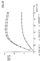
- Figs. 11 and 12 provide graphical comparisons between the operation of the alternative embodiment slider 1300 and the Embodiment three slider 300.
- the comparison of Fig. 12 also considers the performance of a conventional Prior Art "C" slider 1504 (Fig. 9C).
- the graph of Fig. 11 illustrate the low negative pressure achievable for two negative-pressure slider designs of the invention; namely, the slider 1300 and the slider 300.
- the graph of Fig. 12 shows minimum flying height versus velocity for the Prior Art "C” slider 1504, the slider 300, and the slider 1300.
- the slider 1300 of the present invention takes off just as fast from the data storage medium surface as the slider 300, and much faster than the control Prior Art "C” slider 1504.
- the high take-off velocity is a characteristic shared by negative-pressure slider designs.
- the slider 1300 has advantages over presently-existing air bearing slider designs.
- the slider 1300 generates low negative pressure independent of etch depth and flying height.
- This slider also exhibits reduced sensitivity to manufacturing tolerances, and improved performance during the data storage medium access operations.
- the slider features rapid take-off from the surface of the data storage medium.
Description
Claims (3)
- An air bearing slider (10) for supporting a transducer (20) in relation to a movable storage medium (30), said air bearing slider (10) comprising:a slider structure (100, 1300, 1400) with a leading edge (110), a trailing edge (111), and first and second side edges enclosing a slider surface (101), the slider surface facing said movable storage medium when in use;a first (1303, 1403) and a second (1301, 1401) U-shaped rails extending from said slider surface, each U-shaped rail comprising:a cross rail (1317) substantially parallel with said leading edge and extending across substantially less than the one half a width of said slider surface, the cross rail having a tapered portion (1304,) which is adjacent said leading edge of the slider; andfirst (1309, 1409) and second (1313, 1413) side rails, each extending from said cross rail (1317) in the direction of said trailing edge, the first side rail (1309, 1409)) being positioned adjacent a respective side edge and the second side rail (1313, 1413)) being positioned substantially parallel to the first side rail, but being offset from the first side rail toward the opposite edge, the air bearing slider being characterized in that, the second side rail (1313, 1413)) being shorter than the first side rail (1309).
- A slider (10) as claimed in Claim 1, wherein the first side rail (1309, 1409) of each U-shaped rail extends from the leading edge to the trailing edge.
- A slider as claimed in Claim 1, wherein the first side rail (1309) of each U-shaped rail extends to a point offset from the trailing edge, the air bearing slider further including a taper-flat center rail (1305) centered between said two U-shaped rails on said slider surface and extending from said leading edge to said trailing edge.
Applications Claiming Priority (2)
| Application Number | Priority Date | Filing Date | Title |
|---|---|---|---|
| US967359 | 1992-10-28 | ||
| US07/967,359 US5438467A (en) | 1992-10-28 | 1992-10-28 | Negative pressure air bearing design |
Publications (3)
| Publication Number | Publication Date |
|---|---|
| EP0595513A2 EP0595513A2 (en) | 1994-05-04 |
| EP0595513A3 EP0595513A3 (en) | 1994-08-17 |
| EP0595513B1 true EP0595513B1 (en) | 1998-04-22 |
Family
ID=25512688
Family Applications (1)
| Application Number | Title | Priority Date | Filing Date |
|---|---|---|---|
| EP93308245A Expired - Lifetime EP0595513B1 (en) | 1992-10-28 | 1993-10-15 | Negative pressure air bearing slider |
Country Status (5)
| Country | Link |
|---|---|
| US (4) | US5438467A (en) |
| EP (1) | EP0595513B1 (en) |
| JP (1) | JP2577526B2 (en) |
| DE (1) | DE69318100T2 (en) |
| SG (1) | SG44385A1 (en) |
Families Citing this family (30)
| Publication number | Priority date | Publication date | Assignee | Title |
|---|---|---|---|---|
| US5438467A (en) * | 1992-10-28 | 1995-08-01 | International Business Machines Corporation | Negative pressure air bearing design |
| US5568981A (en) * | 1994-08-19 | 1996-10-29 | Read-Rite Corporation | Negative pressure air bearing slider |
| EP0799477B1 (en) * | 1994-12-20 | 2002-06-12 | Seagate Technology LLC | Magnetic head sub-ambient air pressure slider for a disk drive device or the like |
| US6760193B1 (en) * | 1995-04-07 | 2004-07-06 | Hitachi Global Storage Technologies Japan, Ltd. | Magnetic head gimbal assembly and magnetic disk unit |
| KR970003122A (en) * | 1995-06-06 | 1997-01-28 | 토마스 에프. 멀베니 | Center Rail Slider for Proximity Recording |
| US5606476A (en) * | 1995-07-13 | 1997-02-25 | Read-Rite Corporation | Altitude insensitive air bearing slider |
| JPH0935227A (en) * | 1995-07-21 | 1997-02-07 | Sony Corp | Magnetic head device |
| JP2827980B2 (en) * | 1995-08-04 | 1998-11-25 | ティーディーケイ株式会社 | Floating head slider |
| US5661618A (en) * | 1995-12-11 | 1997-08-26 | International Business Machines Corporation | Magnetic recording device having a improved slider |
| US5831791A (en) * | 1996-03-27 | 1998-11-03 | Headway Technologies, Inc. | Negative Pressure air bearing slider having transition region between positive and negative pressure regions |
| US5777825A (en) * | 1996-09-04 | 1998-07-07 | International Business Machines Corporation | Negative pressure step pad air bearing design and method for making the same |
| US5704715A (en) * | 1996-12-09 | 1998-01-06 | Read-Rite Corporation | Altitude insensitive air bearing slider |
| JP3292296B2 (en) | 1997-03-25 | 2002-06-17 | ティーディーケイ株式会社 | Slider, head, head device, and recording / reproducing device |
| KR100296478B1 (en) * | 1997-03-26 | 2001-10-25 | 포만 제프리 엘 | Improved Spindle Motor |
| US6477011B1 (en) | 1998-08-24 | 2002-11-05 | International Business Machines Corporation | Magnetic recording device having an improved slider |
| US6194360B1 (en) | 1998-12-22 | 2001-02-27 | International Business Machines Corporation | Magnetic recording device |
| US6271997B1 (en) * | 1999-11-22 | 2001-08-07 | International Business Machines Corporation | Read head spin valve sensor with triple antiparallel coupled free layer structure |
| WO2001069601A1 (en) | 2000-03-14 | 2001-09-20 | Fujitsu Limited | Negative pressure head slider and disk device |
| US6661611B1 (en) | 2000-10-04 | 2003-12-09 | Seagate Technology Llc | Funneled trench AAB increased contact stiffness and enhanced take-off performance |
| US7123448B1 (en) * | 2000-10-13 | 2006-10-17 | Seagate Technology, Llc | Extended alumina basecoat advanced air bearing slider |
| WO2002035544A2 (en) | 2000-10-25 | 2002-05-02 | Seagate Technology Llc | Disc head slider having convergent channel features with leading edge inlet |
| US6594113B2 (en) * | 2000-12-20 | 2003-07-15 | Seagate Technology Llc | Slider with furrows for flushing contaminants and lubricant |
| US6943989B2 (en) * | 2002-06-07 | 2005-09-13 | Sae Magnetics (H.K.) Ltd. | Subambient pressure slider with partitioned subambient area |
| US6937440B2 (en) * | 2002-07-17 | 2005-08-30 | Seagate Technology Llc | Head slider having convergent channel features with side opening |
| JP4198557B2 (en) * | 2003-07-15 | 2008-12-17 | 富士通株式会社 | Head slider and magnetic disk apparatus having the head slider |
| US7751147B2 (en) * | 2006-01-10 | 2010-07-06 | Hitachi Global Storage Technologies Netherlands B.V. | Air bearing surface with shallow center channel |
| JP2008071453A (en) * | 2006-09-15 | 2008-03-27 | Fujitsu Ltd | Head slider and recording medium drive device |
| US8493688B2 (en) | 2010-08-25 | 2013-07-23 | HGST Netherlands B.V. | Head slider and hard disk drive |
| US8164860B1 (en) | 2010-10-20 | 2012-04-24 | Hitachi Global Storage Technologies Netherlands B.V. | Servo write robust and good altitude performance ABS |
| US8641281B1 (en) | 2012-08-14 | 2014-02-04 | International Business Machines Corporation | Implementing low profile frictional slide mechanism |
Family Cites Families (38)
| Publication number | Priority date | Publication date | Assignee | Title |
|---|---|---|---|---|
| US3678482A (en) * | 1970-08-26 | 1972-07-18 | Burroughs Corp | Multiple surface fluid film bearing |
| US3855625A (en) * | 1973-12-19 | 1974-12-17 | Ibm | Magnetic head slider assembly |
| FR2409571A1 (en) * | 1977-11-18 | 1979-06-15 | Cii Honeywell Bull | PLATFORM CONTAINING AT LEAST ONE MAGNETIC TRANSDUCER FOR READING / WRITING AN INFORMATION MEDIA |
| US4218715A (en) * | 1979-03-12 | 1980-08-19 | International Business Machines Corporation | Magnetic head slider assembly |
| JPS5834007B2 (en) * | 1979-09-18 | 1983-07-23 | 日本電信電話株式会社 | floating head slider |
| JPS5823359A (en) * | 1981-07-31 | 1983-02-12 | Toshiba Corp | Slider for magnetic head |
| US4475135A (en) * | 1981-10-07 | 1984-10-02 | International Business Machines | Magnetic head air bearing slider |
| JPS5958661A (en) * | 1982-09-28 | 1984-04-04 | Fujitsu Ltd | Magnetic head |
| US4555739A (en) * | 1982-11-26 | 1985-11-26 | International Business Machines Corporation | Semi self-loading ferrite head |
| JPS6032174A (en) * | 1983-08-01 | 1985-02-19 | Nec Corp | Floating type magnetic head slider |
| US4636894A (en) * | 1984-03-12 | 1987-01-13 | Censtor Corp. | Recording head slider assembly |
| JPS61148684A (en) * | 1984-12-20 | 1986-07-07 | Fujitsu Ltd | Floating head slider using negative pressure |
| JPS61148685A (en) * | 1984-12-21 | 1986-07-07 | Fujitsu Ltd | Floating head slider using negative pressure |
| JPS61160885A (en) * | 1985-01-09 | 1986-07-21 | Matsushita Electric Ind Co Ltd | Dynamic pressure type floating head |
| JPS63138580A (en) * | 1986-11-28 | 1988-06-10 | Nec Corp | Floating head slider |
| US4802042A (en) * | 1987-02-05 | 1989-01-31 | Magnetic Peripherals Inc. | Side-vented magnetic head air bearing slider |
| JPS63291280A (en) * | 1987-05-22 | 1988-11-29 | Nec Corp | Magnetic head |
| JP2688632B2 (en) * | 1988-03-28 | 1997-12-10 | 株式会社日立製作所 | Floating head slider |
| JPH0253256A (en) * | 1988-08-15 | 1990-02-22 | Sony Corp | Floating head |
| US4894740A (en) * | 1988-09-28 | 1990-01-16 | International Business Machines Corporation | Magnetic head air bearing slider |
| JPH02132688A (en) * | 1988-11-11 | 1990-05-22 | Nec Corp | Floating head slider |
| US5047884A (en) * | 1989-01-17 | 1991-09-10 | Fuji Photo Film Co., Ltd. | Magnetic head having a control portion for generating negative pressure |
| US5097370A (en) * | 1989-03-17 | 1992-03-17 | Digital Equipment Corporation | Subambient pressure air bearing slider for disk drive |
| CA1323421C (en) * | 1989-03-17 | 1993-10-19 | Yiao-Tee Hsia | Disc drive slider configured to counteract roll |
| JP2995068B2 (en) * | 1989-10-07 | 1999-12-27 | ソニー株式会社 | Negative pressure floating head slider |
| JP2779529B2 (en) * | 1989-10-19 | 1998-07-23 | 株式会社日立製作所 | Floating head slider |
| JPH03176878A (en) * | 1989-12-05 | 1991-07-31 | Sony Corp | Head slider device |
| JPH03259480A (en) * | 1990-03-07 | 1991-11-19 | Nec Corp | Magnetic head and magnetic disk device using the head |
| US5128822A (en) * | 1990-05-25 | 1992-07-07 | Seagate Technology, Inc. | Configuration for negative pressure air bearing sliders |
| US5200868A (en) * | 1990-05-25 | 1993-04-06 | Seagate Technology, Inc. | Negative pressure air bearing slider having an air bearing surface trailing a negative pressure cavity |
| US5062017A (en) * | 1990-05-25 | 1991-10-29 | Seagate Technology, Inc. | Hour-glass disk head slider |
| US5210666A (en) * | 1990-05-25 | 1993-05-11 | Seagate Technology, Inc. | Self-loading air bearing slider with a relieved leading edge |
| JPH0432081A (en) * | 1990-05-29 | 1992-02-04 | Kyocera Corp | Negative pressure slider and its manufacture |
| JPH03205671A (en) * | 1990-09-14 | 1991-09-09 | Tdk Corp | Magnetic head |
| US5267109A (en) * | 1991-06-14 | 1993-11-30 | Seagate Technology, Inc. | Air bearing slider with relieved trailing edge |
| US5200867A (en) * | 1991-07-02 | 1993-04-06 | International Business Machines Corporation | Transducer carrier for disk file with liquid film head-disk interface |
| US5287235A (en) * | 1991-10-28 | 1994-02-15 | International Business Machines Corporation | Slider air bearing surface with angled rail configuration |
| US5438467A (en) * | 1992-10-28 | 1995-08-01 | International Business Machines Corporation | Negative pressure air bearing design |
-
1992
- 1992-10-28 US US07/967,359 patent/US5438467A/en not_active Expired - Lifetime
-
1993
- 1993-09-21 JP JP5235018A patent/JP2577526B2/en not_active Expired - Fee Related
- 1993-10-15 DE DE69318100T patent/DE69318100T2/en not_active Expired - Fee Related
- 1993-10-15 EP EP93308245A patent/EP0595513B1/en not_active Expired - Lifetime
- 1993-10-15 SG SG1996000074A patent/SG44385A1/en unknown
-
1995
- 1995-05-01 US US08/431,935 patent/US5798889A/en not_active Expired - Lifetime
-
1997
- 1997-02-27 US US08/806,864 patent/US6449126B1/en not_active Expired - Fee Related
-
1998
- 1998-04-07 US US09/056,404 patent/US6055130A/en not_active Expired - Lifetime
Also Published As
| Publication number | Publication date |
|---|---|
| US5798889A (en) | 1998-08-25 |
| SG44385A1 (en) | 1997-12-19 |
| JPH06195916A (en) | 1994-07-15 |
| US5438467A (en) | 1995-08-01 |
| EP0595513A3 (en) | 1994-08-17 |
| JP2577526B2 (en) | 1997-02-05 |
| DE69318100T2 (en) | 1998-11-19 |
| US6055130A (en) | 2000-04-25 |
| DE69318100D1 (en) | 1998-05-28 |
| EP0595513A2 (en) | 1994-05-04 |
| US6449126B1 (en) | 2002-09-10 |
Similar Documents
| Publication | Publication Date | Title |
|---|---|---|
| EP0595513B1 (en) | Negative pressure air bearing slider | |
| JP2732555B2 (en) | Air bearing slider | |
| US5267109A (en) | Air bearing slider with relieved trailing edge | |
| US6229672B1 (en) | High gram load air bearing geometry for a tripad slider | |
| JP2781467B2 (en) | Disk head slider with air support | |
| RU2106697C1 (en) | Air-cushion slider which keeps recording head with respect to mobile record medium and recording system with disk drive | |
| US6490135B1 (en) | Disc drive assembly having side rail-channeled air bearing for ramp load-unload applications | |
| US5345353A (en) | Step projection air bearing slider with improved stiction performance and wear resistance | |
| US6356412B1 (en) | Air bearing facilitating load/unload of a magnetic read/write head | |
| KR100278422B1 (en) | Design of negative pressure step pad type air bearing and its manufacturing method | |
| US6590746B2 (en) | Negative pressure air-lubricated bearing slider | |
| US5359480A (en) | Magnetic head air bearing slider | |
| US5949617A (en) | Dynamic-absorber for the suppression of suspension vibrations | |
| US20030058578A1 (en) | Disc head slider designs with particle flushing channels | |
| JPH06290562A (en) | Air support magnetic head slider | |
| US6680821B2 (en) | Slider air bearing surface having improved fly height profile characteristics | |
| US6943989B2 (en) | Subambient pressure slider with partitioned subambient area | |
| EP0518566B1 (en) | Air bearing slider with relieved trailing edge | |
| EP0747890A1 (en) | Center rail slider for proximity recording | |
| KR100208382B1 (en) | Air bearing slider with variable sub-ambient pressure control | |
| US6606222B1 (en) | Convergent channel, trenched disc head slider | |
| US6674611B2 (en) | Air bearing design producing steeper ramp profile near the laser texture zone | |
| US5774304A (en) | Disc head slider having center rail with asymmetric edge steps | |
| JPH09265750A (en) | Slider and its formation and system therefor | |
| US5685645A (en) | Roll balance sub-ambient pressure air bearing slider |
Legal Events
| Date | Code | Title | Description |
|---|---|---|---|
| PUAI | Public reference made under article 153(3) epc to a published international application that has entered the european phase |
Free format text: ORIGINAL CODE: 0009012 |
|
| AK | Designated contracting states |
Kind code of ref document: A2 Designated state(s): DE FR GB |
|
| PUAL | Search report despatched |
Free format text: ORIGINAL CODE: 0009013 |
|
| AK | Designated contracting states |
Kind code of ref document: A3 Designated state(s): DE FR GB |
|
| 17P | Request for examination filed |
Effective date: 19940819 |
|
| 17Q | First examination report despatched |
Effective date: 19961213 |
|
| GRAG | Despatch of communication of intention to grant |
Free format text: ORIGINAL CODE: EPIDOS AGRA |
|
| GRAG | Despatch of communication of intention to grant |
Free format text: ORIGINAL CODE: EPIDOS AGRA |
|
| GRAH | Despatch of communication of intention to grant a patent |
Free format text: ORIGINAL CODE: EPIDOS IGRA |
|
| GRAH | Despatch of communication of intention to grant a patent |
Free format text: ORIGINAL CODE: EPIDOS IGRA |
|
| GRAA | (expected) grant |
Free format text: ORIGINAL CODE: 0009210 |
|
| AK | Designated contracting states |
Kind code of ref document: B1 Designated state(s): DE FR GB |
|
| REF | Corresponds to: |
Ref document number: 69318100 Country of ref document: DE Date of ref document: 19980528 |
|
| ET | Fr: translation filed | ||
| PLBE | No opposition filed within time limit |
Free format text: ORIGINAL CODE: 0009261 |
|
| STAA | Information on the status of an ep patent application or granted ep patent |
Free format text: STATUS: NO OPPOSITION FILED WITHIN TIME LIMIT |
|
| 26N | No opposition filed | ||
| PGFP | Annual fee paid to national office [announced via postgrant information from national office to epo] |
Ref country code: FR Payment date: 19991018 Year of fee payment: 7 |
|
| PG25 | Lapsed in a contracting state [announced via postgrant information from national office to epo] |
Ref country code: FR Free format text: LAPSE BECAUSE OF NON-PAYMENT OF DUE FEES Effective date: 20010629 |
|
| REG | Reference to a national code |
Ref country code: FR Ref legal event code: ST |
|
| REG | Reference to a national code |
Ref country code: GB Ref legal event code: IF02 |
|
| REG | Reference to a national code |
Ref country code: GB Ref legal event code: 732E |
|
| PGFP | Annual fee paid to national office [announced via postgrant information from national office to epo] |
Ref country code: GB Payment date: 20071031 Year of fee payment: 15 |
|
| PGFP | Annual fee paid to national office [announced via postgrant information from national office to epo] |
Ref country code: DE Payment date: 20071206 Year of fee payment: 15 |
|
| GBPC | Gb: european patent ceased through non-payment of renewal fee |
Effective date: 20081015 |
|
| PG25 | Lapsed in a contracting state [announced via postgrant information from national office to epo] |
Ref country code: DE Free format text: LAPSE BECAUSE OF NON-PAYMENT OF DUE FEES Effective date: 20090501 |
|
| PG25 | Lapsed in a contracting state [announced via postgrant information from national office to epo] |
Ref country code: GB Free format text: LAPSE BECAUSE OF NON-PAYMENT OF DUE FEES Effective date: 20081015 |