EP0595090A1 - Trocar - Google Patents
Trocar Download PDFInfo
- Publication number
- EP0595090A1 EP0595090A1 EP93116254A EP93116254A EP0595090A1 EP 0595090 A1 EP0595090 A1 EP 0595090A1 EP 93116254 A EP93116254 A EP 93116254A EP 93116254 A EP93116254 A EP 93116254A EP 0595090 A1 EP0595090 A1 EP 0595090A1
- Authority
- EP
- European Patent Office
- Prior art keywords
- trocar
- trigger
- obturator
- tissue
- cannula
- Prior art date
- Legal status (The legal status is an assumption and is not a legal conclusion. Google has not performed a legal analysis and makes no representation as to the accuracy of the status listed.)
- Granted
Links
- 238000003780 insertion Methods 0.000 claims description 18
- 230000037431 insertion Effects 0.000 claims description 18
- 230000001681 protective effect Effects 0.000 description 19
- 210000000056 organ Anatomy 0.000 description 9
- 239000011324 bead Substances 0.000 description 8
- 239000012528 membrane Substances 0.000 description 7
- 238000012360 testing method Methods 0.000 description 7
- 208000014674 injury Diseases 0.000 description 6
- 230000008733 trauma Effects 0.000 description 6
- CURLTUGMZLYLDI-UHFFFAOYSA-N Carbon dioxide Chemical compound O=C=O CURLTUGMZLYLDI-UHFFFAOYSA-N 0.000 description 4
- 230000007246 mechanism Effects 0.000 description 4
- 210000001015 abdomen Anatomy 0.000 description 3
- 210000000683 abdominal cavity Anatomy 0.000 description 3
- 230000003187 abdominal effect Effects 0.000 description 3
- 210000003815 abdominal wall Anatomy 0.000 description 3
- 239000000463 material Substances 0.000 description 3
- 230000000149 penetrating effect Effects 0.000 description 3
- 229920002635 polyurethane Polymers 0.000 description 3
- 239000004814 polyurethane Substances 0.000 description 3
- 229910002092 carbon dioxide Inorganic materials 0.000 description 2
- 239000001569 carbon dioxide Substances 0.000 description 2
- 210000003195 fascia Anatomy 0.000 description 2
- 230000037368 penetrate the skin Effects 0.000 description 2
- 230000035515 penetration Effects 0.000 description 2
- 229920001084 poly(chloroprene) Polymers 0.000 description 2
- 238000001356 surgical procedure Methods 0.000 description 2
- 229910001250 2024 aluminium alloy Inorganic materials 0.000 description 1
- 229920004142 LEXAN™ Polymers 0.000 description 1
- 239000004418 Lexan Substances 0.000 description 1
- 206010042618 Surgical procedure repeated Diseases 0.000 description 1
- 230000009471 action Effects 0.000 description 1
- 230000006835 compression Effects 0.000 description 1
- 238000007906 compression Methods 0.000 description 1
- 239000012141 concentrate Substances 0.000 description 1
- 230000003993 interaction Effects 0.000 description 1
- 238000002357 laparoscopic surgery Methods 0.000 description 1
- 238000000034 method Methods 0.000 description 1
- 229920000515 polycarbonate Polymers 0.000 description 1
- 239000004417 polycarbonate Substances 0.000 description 1
- 230000009467 reduction Effects 0.000 description 1
- 230000004044 response Effects 0.000 description 1
- 230000001960 triggered effect Effects 0.000 description 1
Images


Classifications
-
- A—HUMAN NECESSITIES
- A61—MEDICAL OR VETERINARY SCIENCE; HYGIENE
- A61B—DIAGNOSIS; SURGERY; IDENTIFICATION
- A61B17/00—Surgical instruments, devices or methods, e.g. tourniquets
- A61B17/34—Trocars; Puncturing needles
- A61B17/3494—Trocars; Puncturing needles with safety means for protection against accidental cutting or pricking, e.g. limiting insertion depth, pressure sensors
- A61B17/3496—Protecting sleeves or inner probes; Retractable tips
-
- A—HUMAN NECESSITIES
- A61—MEDICAL OR VETERINARY SCIENCE; HYGIENE
- A61B—DIAGNOSIS; SURGERY; IDENTIFICATION
- A61B17/00—Surgical instruments, devices or methods, e.g. tourniquets
- A61B17/34—Trocars; Puncturing needles
- A61B17/3417—Details of tips or shafts, e.g. grooves, expandable, bendable; Multiple coaxial sliding cannulas, e.g. for dilating
Definitions
- the proximal motion of the point 208 causes the point to be quickly moved away from the underlying organs.
- the proximal end of the button 152B projects through the opening in the handle, nudging the palm of the user and providing a positive tactile signal that the trocar has penetrated the tissue 201.
- the user will have information as to when to stop advancing the trocar 200.
Abstract
Description
- The present invention is directed to trocars for inserting an access tube through an abdominal wall, and more particularly to a trocar having an improved obturator and trigger.
- An increasing number of abdominal surgical procedures are being performed with laparoscopic techniques in order to avoid a large skin incision. Typically in laparoscopic surgery, a special needle (a needle similar to the pneumoneedle described in U.S. Patent No. 4,808,168 is inserted through the skin, and used to inflate the abdominal cavity with an insufflating gas such as carbon dioxide (CO₂). Once the abdomen is adequately dilated, the needle is removed and a rigid access tube or cannula with a diameter larger than the pneumoneedle (for example 5, 10 or 11 mm) is passed through the skin in the same location.
- The access tube provides access for laparoscopes or other laparoscopic surgical tools such as the stapler described in U.S. Patent No. 5,040,715 or the surgical clip appliers described in U.S. Patent No.'s 5,084,057 and 5,100,420. To drive the access tube through the skin, the surgeon places a trocar in the lumen of the access tube to provide a sharp, leading edge for cutting tissue.
- The art is replete with trocar devices, including those shown in U.S. Patent Nos. 4,535,773, 4,601,710, 4,654,030, 4,902,280 and 4,931,042. Those trocars typically comprise an obturator with cutting surfaces for penetrating the skin, and a spring-loaded protective sleeve that surrounds the obturator. As these trocar devices are urged through the skin, friction with the skin causes the protective sleeve to slide proximally (rearwardly). After the access tube has penetrated through the skin, there is no longer friction between the protective sleeve and the skin, and the spring is designed to urge the protective sleeve distally (forwardly) to cover the cutting surfaces. Some of those trocars lock the protective sleeve in the forward position to reduce the risk of accidental puncture of the underlying organs.
- These prior art trocars rely on a similar principle of operation: The friction or drag on the protective sleeve as the trocar is advanced through the skin pushes the protective sleeve back (proximally) to expose the cutting surfaces. Once the access tube has penetrated the skin, the drag on the protective sleeve is reduced and the sleeve accelerates distally (forwardly) under the bias of the spring to cover the cutting surfaces.
- Figure 1 illustrates a portion of a typical prior art trocar similar to the 10mm Auto Suture Surgiport T.M., generally available from U.S. Surgical of Norwalk, Conn. That trocar includes an
access tube 1, anobturator 2 and a shield 3. The shield 3 is biased distally to cover theobturator 2. The shield 3 comprises a generally cylindrical tube with a slightly rounded orangled end portion 4. - Existing trocars such as the trocar shown in Figure 1 encounter problems because a significant amount of force usually must be applied to penetrate the skin (particularly the tough fascia). As a result of the significant insertion force, the trocar may continue to advance toward the underlying organs after it has penetrated the skin. Thus, the protective sleeve must "catch up" to the moving trocar point before the trocar reaches the underlying organs.
- Figure 2 illustrates another prior art trocar. This Figure generally illustrates a portion of trocar that is currently being sold in the United States under the
name 10/11 mm Endopath™ (generally available from Ethicon of Somerville, N.J). U.S. Patent No. 5,066,288 to Deniega et al. describes a trocar similar to the trocar shown in Figure 2. That trocar includes anaccess tube 5, anobturator 6 and a shield 7. The shield 7 is biased distally to cover theobturator 6. Unlike other trocars, the shield 7 of the trocar shown in Figure 2 includes a bullet shapedend portion 8 comprising threesemicircular lobes 9. - U.S. Patent No. 5,066,288 states that the trocar restricts tissue trauma. However, like the trocar shown in Figure 1, trocars similar to those shown in Figure 2 also encounter problems because a significant amount of force is nevertheless required to penetrate the skin (particularly the tough fascia). Again, as a result of the significant insertion force, the obturator may continue to advance toward the underlying organs even after it has penetrated the skin.
- Figures 3 and 4 illustrate yet another trocar similar to the trocar described in U.S. Patent No. 4,654,030 to Moll. That trocar includes an access tube (not shown), an
obturator 10 and shield 11 that is biased distally to cover theobturator 10. The obturator has atriangular base 12, and three generally equilateraltriangular surfaces 13. - The shield 11 comprises three parabolically
shaped bevels 14 which form a triangularshaped opening 15. The parabolically shapedbevels 14 intersect at threeedges 16. While U.S. Patent 4,654,030 states that the trocar shown in Figures 3 and 4 markedly reduces the force required to insert the trocar into body cavities, the trocar shown in Figures 3 and 4 is believed to suffer from several drawbacks including: (1) the shield 11 is believed to concentrate tissue trauma generally at theedges 16 during insertion into the body cavity resulting in undesirable tissue trauma at the incision site, (2) the shield 11 (particularly the edges 16) may become caught on tissue which restricts movement of the shield 11 relative toobturator 10, which is particularly undesirable after the obturator has pierced the abdominal wall; and (3) theedges 16 of the shield 11 may be relatively sharp and may expose the underlying organs to damage from contact with theedges 16 of the shield 11 itself. - U.S. Patent No. 5,152,754 discloses a trocar comprising an obturator which retracts relative to the access tube just after the obturator pierces the tissue defining the body cavity.
- According to the present invention there is provided a trocar having an improved obturator and trigger which (1) affords an acceptable amount of force required to insert the trocar into the abdominal cavity, (2) restricts force concentrations (and tissue trauma) at the incision site due to the shape of the trigger; (3) obscures any potential sharp edges on the trigger to restrict the chances of the trigger catching tissue or other structures which may inhibit the trigger's movement relative to the access tube after the trigger has penetrated into the body cavity; (4) restricts damage to underlying organs due to the shape of the trigger; and (5) resists binding or rotation of the obturator relative to the trigger.
- According to the present invention, there is provided an improved trocar assembly having a novel obturator and trigger. The trocar is placed in the lumen of a cannula to facilitate insertion of the cannula through tissue defining a body cavity.
- The trocar comprises a handle, and an elongate obturator which extends from the handle. The direction of elongation of the obturator and its center define a longitudinal axis. The obturator comprises cutting surfaces for cutting and penetrating the tissue defining the body cavity, and a trigger having a plurality of tissue cams. Each tissue cam comprises an inner surface and an outer, generally planar surface situated at an angle relative to the longitudinal axis. Each tissue cam also has a distal end portion that is arcuate about an axis normal to the outer surface.
- Each of the distal end portions of the trigger has a distal most point. The distal end portions of the tissue cams intersect at edge portions. The distal most points of the distal end portions are spaced distally from the edge portions.
- Optionally, the trocar includes a mechanism for restricting rotation of the obturator relative to the trigger. Such a mechanism may comprise the trigger having a detent member, and the obturator having a generally cylindrical base portion having a chamfered edge that engages the detent member.
- Preferably, the trigger is mounted around the obturator. The trigger is adapted to move longitudinally and axially movement relative to the obturator. The trigger retracts proximally relative to the obturator as the trocar is advanced through the tissue defining the body cavity. The trigger advances distally after the cannula has penetrated through the tissue defining the body cavity.
- Also, preferably, the trocar includes a mechanism for retracting the obturator proximally relative to the cannula after the obturator has cut the tissue defining the body cavity. More preferably, the obturator retracts proximally after the trigger advances distally.
- Alternatively but not preferably, the present invention may comprise a trocar comprising an obturator defining a longitudinal axis and a protective sleeve having a plurality of tissue cams. The protective sleeve's tissue cams each have an inner surface and an outer, generally planar surface situated at an angle relative to the longitudinal axis. Each of the protective sleeve's tissue cams also have a distal end portion that is arcuate about an axis normal to the outer surface. Preferably, the distal end portions of the tissue cams intersect at edge portions. Distal most points of the distal end portions are spaced distally from the edge portions of the protective sleeve.
- The present invention will be further described with reference to the accompanying drawing wherein like reference numerals refer to like parts in the several views, and wherein:
- Figure 1 is a partial side view of a prior art trocar illustrating penetration of tissue by the trocar;
- Figure 2 is a partial side view of a second, bullet nosed prior art trocar illustrating penetration of tissue by the trocar;
- Figure 3 is a perspective view of a third prior art trocar obturator having portions broken away to show details;
- Figure 4 is a perspective view of the obturator of Figure 3 assembled with a sleeve in a retracted position;
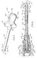
- Figure 5 is a perspective view of a trocar assembly according to the present invention;
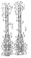
- Figure 6 is a sectional view illustrating the relative positions of the obturator and trigger after a button of the trocar has been pressed and just prior to insertion into the abdominal cavity;
- Figure 7 is a sectional view illustrating the relative positions of the obturator and trigger as the trocar just begins to pierce the tissue defining the body cavity;
- Figure 8 is a sectional view illustrating the relative positions of the obturator and trigger after the obturator has pierced the tissue defining the body cavity and after the obturator has retracted relative to the trocar handle;
- Figure 9 is an enlarged end view of the trocar assembly of Figure 5;
- Figure 10 is a sectional view of the trocar assembly of Figure 5 taken approximately along lines 10-10 of Figure 5 and with portions broken away to emphasize detail; and
- Figure 11 is an enlarged perspective view of the novel trigger forming a portion of the present invention having portions broken away to emphasize details.
- Referring now to Figures 5 through 11 of the drawing there is shown an embodiment of a trocar device or assembly generally designated by
reference character 200. Thetrocar 200 is similar to the trocar described in U.S. Patent No. 5,152,754. Features of thetrocar 200 that are similar to the features of the trocar described in U.S. Patent No. 5,152,754 have been given the same reference character to which the suffix "B" has been added. - The
trocar 200 includes the novel obturator and trigger according to the present invention. Thetrocar 200 facilitates insertion of a cannula through tissue defining a body cavity, for example inserting anaccess tube 102B through anabdominal wall 201. Theaccess tube 102B comprises acannula 104B that has anenlarged fixture 106B at its proximal end similar to the fixture 106 described in U.S. Patent No. 5,152,754. There is anopening 110B at the proximal end of the chamber similar to the opening 110 in U.S. Patent No. 5,152,754. - A trap
door valve member 112B similar to trap door valve member 112 (in U.S. Patent No. 5,152,754) is also present to close theopening 110B. Thevalve member 112B is operated by apushbutton 116B similar to the pushbutton 116 (again further shown in U.S. Patent No. 5,152,754). - The
trocar 200 has a stopcock (not shown) by which pressurized gas (insufflating gas) can be provided to the chamber to maintain the gas pressure in the body cavity, and thereby keep the cavity inflated to facilitate the surgical procedure. - The
trocar 200 comprises a handle orhousing 126B that is releasably attached to thefixture 106B so that after thetrocar 200 is used to insert theaccess tube 102B in the tissue defining the body cavity, thetrocar 200 can be removed leaving theaccess tube 102B. Thetube 102B can then be used to introduce surgical instruments into the body cavity. - The proximal end of the
fixture 106B has a funnel-shapedextension 128B, with anenlarged rim 130B. Resilient fingers are also present and have a shoulder to engage therim 130B and attach thehandle 126B to thefixture 106B. The sides of the handle have two pivotally mountedbuttons 138B which operate similar to the buttons 138 described in U.S. Patent No. 5,152,754. - The
trocar 200 also includes anobturator 240 extending from the distal end of thehandle 126B. Note Figures 6-8. The direction of elongation of theobturator 240 and its center defines an imaginary, longitudinal axis I. The trocar also includestrigger 242 mounted around theobturator 240 for axial movement relative to theobturator 240. Thetrigger 242 is preferably mounted so that it can retract proximally relative to theobturator 240 in response to drag from thetissue 201 defining the body cavity as it is advancing through thetissue 201. The trigger can then advance distally after the cannula oraccess tube 102B has penetrated through thetissue 201 and reduced the drag on thetrigger 242. - The
obturator 240 comprises proximal 204 and distal 205 end portions. Thedistal end portion 205 comprises abase part 206 and also has generally planar surfaces 207 (preferably three) intersecting to form cutting edges or surfaces (again preferably three) and apoint 208 at the distal most end of the obturator. The axis I is generally parallel to the direction of elongation of theobturator 240 and passes throughpoint 208. -
Trigger 242 has proximal and distal end portions with the proximal end portion attached totrocar adapter 211. Unlike trigger 142 shown in U.S. Patent No. 5,152,754, the distal end of thetrigger 242 comprises threetissue cams 244. Each of thetissue cams 244 has aninner surface 245 and a planarouter surface 246 situated generally at an angle relative to the longitudinal axis I. Preferably, the included angle between theouter surface 246 and the axis I is between about 10 degrees and about 40 degrees. Most preferably, the angle is about 15 degrees. - The
cams 244 are believed to beneficially reduce the insertion force required to insert thetrocar 200 through theabdominal tissue 201. Thecams 244 each include a novelarcuate end portion 250 that is arcuate about an axis N normal to the outer surface 246 (See Figure 8). - For example, when the
trocar 200 is used to insert acannula 104B having an lumen interior diameter of about 10 millimeters, the radius of curvature of thearcuate end portion 250 should be between about 0.18 inches and about 0.32 inches, and preferably approximately 0.25 inches. - The
distal end portions 250 each have a distalmost point 252. Thedistal end portions 250 of thecams 244 intersect atedge portions 255. The distalmost points 252 of thedistal end portions 250 are spaced distally (relative to thefixture 106B) from theedge portions 255. - While not desiring to be bound by any particular theory, it is believed that the
arcuate end portions 250 distribute the insertion force applied to thetissue 201 by thetrigger 242 more evenly, than for example, a structure as shown in Figure 4. Thearcuate end portions 250 thus restrict trauma to thetissue 201. Additionally, the arcuatedistal end portions 250 of thetrigger 242 are believed to (1) obscure any potential sharp edges on the trigger 242 (e.g. portions 255) (2) restrict the opportunity for thetrigger 242 to catch tissue which may inhibit the trigger's distal movement after it has penetrated into the body cavity; and (3) restrict damage to underlying organs due to the blunt shape of theend 250 itself. Unlike prior art trocars, the potentiallysharp portions 255 are obscured by thearcuate end portions 250. Thearcuate end portions 250 restrict damage to underlying organs from contact with the trigger itself. - The
trocar 200 optionally includes means for restricting rotation of theobturator 240 relative to thetrigger 242. That means may comprise thetrigger 242 having inner and outer surfaces with the inner surface having a detent portion 243 (Note Figure 6). The means also includes thebase part 206 of the obturator provided in a generally cylindrical shape with a chamfered edge 263 (Note Figure 10) for engaging thedetent member 243 of thetrigger 242. The means described in this paragraph is believed to restrict binding or rotation of the obturator and/or trigger relative to the housing of thetrocar 200. - The
trigger 242 is resiliently biased distally (relative to the housing or handle 126B). In the embodiment shown in Figures 5-11, thetrigger 242 is biased with a spring (not shown), similar to the coil spring 146 shown in U.S. Patent No. 5,152,754. The distal end of the spring (not shown) is supported on aninternal shoulder 148B on the trigger, and its proximal end engages a raised shoulder on the obturator (described in more detail below). - The action of the spring (not shown but similar to spring 146 in U.S. Patent No. 5,152,754) resiliently biases the
trigger 242 distally. However, the trigger can move proximally against the bias, under the forces applied by the tissue defining the body cavity as thetrocar 200 is advanced through thetissue 201. Thetrigger 242 has a "resilient" characteristic and moves distally when the applied forces are removed, as occurs once theaccess tube 102B is inserted through thetissue 201 and thetrigger 242 is no longer in frictional contact with thetissue 201. - The
trocar 200 also comprises means for retracting thepoint 208 on theobturator 240 relative to thecannula 104B after the point has penetrated through thetissue 201, thereby reducing the risk that thepoint 208 will cause damage inside the body cavity. - In
trocar 200, the retracting means is triggered upon the distal (forward) movement of thetrigger 242. When thenovel obturator 240 and trigger 242 are used with thetrocar 200, it is important that the trigger move distally so that the retracting means of thetrocar 200 may operate. Thearcuate surface portions 252 obscure the relatively pointedstructures 255 to restrict the chances that thetrigger 242 will catch tissue which might prevent thetrigger 242 from moving distally and "triggering" the retracting means. - Like the embodiment shown in U.S. Patent No. 5,152,754, in the
trocar 200, there is atubular extension 150B secured on a shoulder on the proximal end of theobturator 240. Anenlarged head 152B is secured onto the proximal end of theextension 150B. Theextension 150B has a generally radially extending flange 154B. The distal surface of the flange 154B forms the shoulder that engages the proximal end of the spring (not shown). Preferably four proximally extendingresilient fingers 156B are disposed around the obturator. - The proximal ends of the
fingers 156B havebeads 158B that can engage the flange 154B on theextension 150B, and thereby hold the obturator against proximal retraction under the bias of spring (not shown but similar to spring shown in U.S. Patent No. 5,152,754). The distal ends of thefingers 156B are anchored to aring 157B. Thering 157B is supported on a generally cylindrical base similar to the base 159 shown in U.S. Patent No. 5,152,754. - Before use, as shown in Figure 6, the
beads 158B on thefingers 156B engage the flange 154B, holding the spring (not shown) in compression and holding theobturator 240 from proximal retraction. A lockingmember 160B, slidably mounted on the proximal portion of theextension member 150B, locks thefingers 156B in engagement with the flange 154B. The bottom edge of the lockingmember 160B hasnotches 162B which, when the lockingmember 160B is in its distal most position, receive and engage thefingers 156B and hold thebeads 158B in engagement with the shoulder. - The
cylindrical section 144B of thetrigger 242 is sized and positioned to engage the lockingmember 160B, and slide the locking member proximally as thetrigger 242 slides proximally (as occurs as thetrocar 200 is advanced through thetissue 201 and the friction of the tissue acts against the trigger 242). - As shown in Figures 6-7, when the
trigger 242 moves proximally, it pushes the lockingmember 160B proximally. Thereafter, further proximal movement of thetrigger 242 moves the lockingmember 160B. Thecylindrical section 144B of thetrigger 242 is sized to engage thefingers 156B, and hold thebeads 158B in engagement with the flange 154B after the lockingmember 160B has been displaced. Thus, as shown in Figure 7, when thetrigger 242 is in its fully retracted position, the lockingmember 160B has been moved proximally, and the walls of thecylindrical section 144B hold thefingers 156B in engagement with the flange 154B. - The mechanism of the
trocar 200 is now primed so that any distal advancement of thetrigger 242 will cause thetrocar 200 to retract theobturator point 208. Thus, the importance of permitting this distal advancement is apparent. - When the
cannula 104B ofaccess tube 102B pierces through thetissue 201, it shields thetrigger 242 from contact with thetissue 201, and thus thetissue 201 no longer exerts frictional force on thetrigger 242. The reduction in force on the trigger allows thetrigger 242 to advance distally under the bias of the spring (not shown). This distal advancement is believed to be facilitated by the shape of thecams 244 of thetrigger 242. - As the
trigger 242 advances, thecylindrical section 144B releases thefingers 156B. When thefingers 156B are released, they spring resiliently outwardly, and thebeads 158B clear the flange 154B. This allows theobturator 240 to retract under the bias of the spring (not shown). - As the
obturator 240 retracts, it moves the lockingmember 160B with it. Moreover, thecap 152B protrudes through an opening in thehandle 126B providing a visible signal, as well as a tactile signal that theobturator point 208 has retracted. - As shown in Figure 8, the
point 208 of the obturator retracts relative to thecannula 104B to a retracted position. Alternatively, thepoint 208 of the obturator may be designed to retract completely within the lumen of thecannula 104B so that the tip is located proximally relative to the distal end of thecannula 104B. This may conveniently be accomplished by increasing the length of travel of flange 154B between the position shown in Figure 7 and the position shown in Figure 8. - The operation of the trocar will now be described with reference to Figures 6 through 8 which sequentially illustrate the operation of the trigger. The
trocar 200 optionally includes a protective cap (not shown) over thepoint 208 that is removed prior to use of thetrocar 200. Theaccess tube 104B is already installed over the distal end of thetrocar 200. The user grasps the handle of thetrocar 200, with the palm of the hand over the proximal end. - The
trocar 200 is advanced against thetissue 201 defining a body cavity, for example the abdomen. The arcuate end surfaces 252 are believed to distribute the insertion force applied by thetrigger 242 to thetissue 201 over a greater area than would, for example, a flat, planar surface. The shape of thearcuate end surface 252 is also believed to restrict force concentrations on thetissue 201 to thereby restrict tissue trauma. - As the
trocar 200 is advanced, friction or drag from the skin urges thetrigger 242 proximally. As thetrigger 242 moves proximally, its enlarged proximal end also moves proximally. - The proximal end of the
trigger 242 pushes the lockingmember 160B proximally, releasing thenotches 162B from their engagement with thefingers 156B, while the enlarged end ofcylindrical section 144B simultaneously moves over the fingers to continue to hold thebeads 158B in engagement with the shoulder (Compare Figures 6 and 7). The user continues to advance the trocar, penetrating thetissue 201. - Once the
cannula 104B has penetrated through thetissue 201, the drag on thetrigger 242 is reduced, and the spring (not shown) urges thetrigger 242 distally. The distal motion of thetrigger 242 also causes the enlarged end to move distally, releasing thefingers 156B. Thefingers 156B are displaced radially outwardly, releasingbeads 158B from their engagement with the shoulder. This allows the spring (not shown) to expand, pushing theobturator 240 proximally (Compare Figures 7 and 8). Thus thepoint 208 begins to move proximally, i.e., it retracts. - The proximal motion of the
point 208 causes the point to be quickly moved away from the underlying organs. As the obturator retracts, the proximal end of thebutton 152B projects through the opening in the handle, nudging the palm of the user and providing a positive tactile signal that the trocar has penetrated thetissue 201. Thus the user will have information as to when to stop advancing thetrocar 200. - The user then grasps the
fixture 106B of theaccess tube 102B, and pulls the trocar proximally, leaving theaccess tube 102B in theabdominal tissue 201. As noted above, the access tube preferably has a trap-door valve that closes thecannula 104B when the trocar is withdrawn to prevent the escape of gas from the abdomen. The trocar can be quickly prepared for reuse (on the same patient) by pressing the enlarged end of thebutton 152B down through theopening 178B, until thebeads 158B on thefingers 156B engage theshoulder 144B, and thenotches 162B on the lockingmember 160B hold the fingers in place. Another access tube can be placed over thetrocar 200, and the procedure repeated. - The present invention has been described above in relation to the
trocar 200 which has a means for retracting theobturator 240 relative to accesstubes 102B. However, alternatively, but not preferably, the present invention may be used in conjunction with a trocar with an obturator that remains relatively stationary with respect to its cannula. For example, the present invention may comprise a protective sleeve having the shape shown in Figure 11. The protective sleeve shown in Figure 11 may be used, for example, to replace the protective sleeves shown in U.S. Patent No's. 4,535,773; 4,654,030; 4,931,042; and 5,066,288. - Insertion force tests were conducted using an obturator and four different shaped structures. The insertion force for the four structures was separately measured through two different materials: 1. a 0.125 inch membrane of Neoprene™, and 2. a 0.030 inch membrane of Polyurethane. The structures were sized to approximate a protective sleeve or trigger for a 10mm trocar. The location of insertion of the four tips into the membranes was randomly assigned.
- The first structure (structure A) was a generally cylindrical shaped structure. The second structure (structure B) comprised the trigger/protective sleeve structure according to the present invention. See Figure 11. The third structure (structure C) comprised a structure generally as shown in Figure 4. Finally, the fourth structure (structure D) comprised a structure generally as shown in Figure 2, and was taken from a 10mm Ethicon Endopath™ trocar, generally available from Ethicon of Somerville, New Jersey. Structures A, B and C were constructed from Lexan HPS #1-1125 polycarbonate, generally available from General Electric (GE).
- Referring now to Table 1, the obturator tip shape for use with the above structures was selected as either a triangular (2,3) or triangular, with a flat edge (1,4) (to prevent rotation of the sleeve relative to the obturator). All of the obturator tips were constructed from the same material (ASTM #2024 Aluminum). All of the obturators were sharpened initially.

- The test was performed as follows. An Instron brand force testing machine (with a 1000 pound load cell) was selected to measure insertion force. The force was measured in pounds. The obturator and sleeve structures (e.g. A-D) were placed in a generally vertical position and the membrane was placed in a generally horizontal orientation. A fixture was used to fix the relative positions of the obturator and the sleeve structures (A-D). The relative positions of obturator and sleeve structures were manually chosen, but the positions were chosen to approximate the positions of the structure (A-D) relative to the obturator as the trocar is passed through tissue. For example, the end of the cylindrical shaped structure (A) was placed just proximal to the end of the cutting surface of the obturator. Note that no cannula was used in these tests.
- The combination sleeve/obturator assembly was moved in a direction normal to the surface of the membrane and toward the membrane at a speed of approximately fifty (50) inches per second. Average Peak Insertion Force test results are shown in Table 2.
TABLE 2 Average Peak Insertion Forces (lbs) Shape/Material A B C D Neoprene 2.25 2.36 3.12 2.93 Polyurethane 5.16 5.85 7.25 8.95 - The Neoprene and Polyurethane membranes were selected to approximate tissue. Additionally, the relative positions of the test structures A-D and the obturator were manually positioned to approximate their orientation as a trocar is passed through tissue. However, factors too numerous to list here may affect the actual insertion force for a trocar. For example, the spring constant of the trocar, the sharpness of the obturator, the interaction of the sleeve/obturator and cannula (note no cannula used in this test), the friction constant of the sleeve, and the size of the obturator may all affect the actual insertion force encountered by a surgeon.
Claims (11)
- A trocar for placement in the lumen of a cannula to facilitate insertion of the cannula through tissue defining a body cavity, the cannula having a distal end,
said trocar comprising:
a handle,
an elongate obturator extending from said handle and defining a longitudinal axis, said obturator comprising cutting surfaces for cutting the tissue defining the body cavity, and
a trigger having portions adapted to project beyond the distal end of the cannula, said trigger having a plurality of tissue cams, each tissue cam comprising an inner surface and an outer planar surface situated at an angle relative to said longitudinal axis, and a distal end portion that is arcuate about an axis normal to the outer surface. - A trocar according to claim 1 wherein each of said distal end portions has a distal most point,
said distal end portions of said tissue cams intersect at edge portions, and
said distal most points of said distal end portions are spaced distally from said edge portions. - A trocar according to claim 1 or 2 wherein the trocar comprises means for restricting rotation of the obturator relative to the trigger.
- A trocar according to claim 3 wherein said means for restricting rotation of the obturator relative to the trigger comprises a detent member on the trigger, and the obturator having a cylindrical base portion with a chamfered edge for engaging the detent member.
- A trocar according to any one of claims 1 to 4 wherein said trigger is mounted around the obturator, and the trocar includes means for affording movement of the trigger longitudinally relative to said obturator,
wherein the trocar includes means for affording retraction of the trigger proximally relative to the obturator as the trocar is advanced through the tissue defining the body cavity, and
wherein the trocar further includes means for advancing the trigger distally after the cannula has penetrated through the tissue defining the body cavity. - A trocar according to claim 5 wherein said trocar includes means for retracting the obturator proximally relative to said cannula after said obturator has cut the tissue defining the body cavity.
- A trocar according to claim 6 wherein said obturator retracts proximally after said trigger advances distally.
- A trocar according to any one of claims 1 to 7 wherein the lumen of the cannula has a diameter of ten (10) millimeters, and
each of the distal end portions of the trigger has a radius of curvature from 0.18 inches to 0.32 inches. - A trocar according to claim 8 wherein each of the distal end portions of the trigger has a radius of curvature of 0.25 inches.
- A trocar according to any one of claims 1 to 9 wherein the outer surface of said tissue cam is located at an angle between 10 degrees and 40 degrees relative to the longitudinal axis.
- A trocar according to claim 10 wherein the outer surface of said tissue cam is located at an angle of 15 degrees relative to the longitudinal axis.
Applications Claiming Priority (2)
| Application Number | Priority Date | Filing Date | Title |
|---|---|---|---|
| US95896492A | 1992-10-09 | 1992-10-09 | |
| US958964 | 1992-10-09 |
Publications (2)
| Publication Number | Publication Date |
|---|---|
| EP0595090A1 true EP0595090A1 (en) | 1994-05-04 |
| EP0595090B1 EP0595090B1 (en) | 1997-03-12 |
Family
ID=25501499
Family Applications (1)
| Application Number | Title | Priority Date | Filing Date |
|---|---|---|---|
| EP93116254A Expired - Lifetime EP0595090B1 (en) | 1992-10-09 | 1993-10-07 | Trocar |
Country Status (5)
| Country | Link |
|---|---|
| US (1) | US5533977A (en) |
| EP (1) | EP0595090B1 (en) |
| JP (1) | JP2589170Y2 (en) |
| CA (1) | CA2107852C (en) |
| DE (1) | DE69308725T2 (en) |
Cited By (2)
| Publication number | Priority date | Publication date | Assignee | Title |
|---|---|---|---|---|
| US5405328A (en) * | 1992-06-17 | 1995-04-11 | Minnesota Mining And Manufacturing Company | Trocar with replaceable obturator |
| US5453094A (en) * | 1993-09-17 | 1995-09-26 | Minnesota Mining And Manufacturing Company | Kit assembly for use during a laparoscopic surgical procedure |
Families Citing this family (32)
| Publication number | Priority date | Publication date | Assignee | Title |
|---|---|---|---|---|
| US6228058B1 (en) * | 1997-04-03 | 2001-05-08 | Core Dynamics, Inc. | Sleeve trocar with penetration indicator |
| JP3359646B2 (en) * | 1997-10-01 | 2002-12-24 | ドクタージャパン株式会社 | Medical anesthesia needle |
| US6030364A (en) * | 1997-10-03 | 2000-02-29 | Boston Scientific Corporation | Apparatus and method for percutaneous placement of gastro-intestinal tubes |
| WO2001089399A2 (en) * | 2000-05-25 | 2001-11-29 | Tyco Healthcare Group Lp | Trocar assembly with cushioned activator |
| WO2002083004A1 (en) * | 2001-04-16 | 2002-10-24 | Kyphon Inc. | Insertion devices and method of use |
| US8571624B2 (en) | 2004-12-29 | 2013-10-29 | Abbott Diabetes Care Inc. | Method and apparatus for mounting a data transmission device in a communication system |
| US7731657B2 (en) | 2005-08-30 | 2010-06-08 | Abbott Diabetes Care Inc. | Analyte sensor introducer and methods of use |
| US10226207B2 (en) | 2004-12-29 | 2019-03-12 | Abbott Diabetes Care Inc. | Sensor inserter having introducer |
| US8333714B2 (en) | 2006-09-10 | 2012-12-18 | Abbott Diabetes Care Inc. | Method and system for providing an integrated analyte sensor insertion device and data processing unit |
| US9788771B2 (en) | 2006-10-23 | 2017-10-17 | Abbott Diabetes Care Inc. | Variable speed sensor insertion devices and methods of use |
| US9743862B2 (en) | 2011-03-31 | 2017-08-29 | Abbott Diabetes Care Inc. | Systems and methods for transcutaneously implanting medical devices |
| US9572534B2 (en) | 2010-06-29 | 2017-02-21 | Abbott Diabetes Care Inc. | Devices, systems and methods for on-skin or on-body mounting of medical devices |
| US8512243B2 (en) | 2005-09-30 | 2013-08-20 | Abbott Diabetes Care Inc. | Integrated introducer and transmitter assembly and methods of use |
| US7697967B2 (en) | 2005-12-28 | 2010-04-13 | Abbott Diabetes Care Inc. | Method and apparatus for providing analyte sensor insertion |
| US20090105569A1 (en) | 2006-04-28 | 2009-04-23 | Abbott Diabetes Care, Inc. | Introducer Assembly and Methods of Use |
| US7883464B2 (en) | 2005-09-30 | 2011-02-08 | Abbott Diabetes Care Inc. | Integrated transmitter unit and sensor introducer mechanism and methods of use |
| US9398882B2 (en) | 2005-09-30 | 2016-07-26 | Abbott Diabetes Care Inc. | Method and apparatus for providing analyte sensor and data processing device |
| DE102005010062B4 (en) * | 2005-03-04 | 2007-06-28 | Karl Storz Gmbh & Co. Kg | Gasinsufflationsvorrichtung |
| US11298058B2 (en) | 2005-12-28 | 2022-04-12 | Abbott Diabetes Care Inc. | Method and apparatus for providing analyte sensor insertion |
| EP1968432A4 (en) | 2005-12-28 | 2009-10-21 | Abbott Diabetes Care Inc | Medical device insertion |
| JP5327748B2 (en) * | 2006-12-15 | 2013-10-30 | コヴィディエン リミテッド パートナーシップ | Design of trocar assembly with obturator |
| WO2008103400A2 (en) * | 2007-02-21 | 2008-08-28 | Tyco Healthcare Group Lp | Obturator tips |
| JP5580054B2 (en) * | 2007-02-28 | 2014-08-27 | コヴィディエン リミテッド パートナーシップ | Trocar assembly with obturator and retractable stylet |
| US8940007B2 (en) * | 2007-04-18 | 2015-01-27 | Covidien Lp | Trocar assembly with obturator dissector |
| WO2008150917A1 (en) * | 2007-05-31 | 2008-12-11 | Abbott Diabetes Care, Inc. | Insertion devices and methods |
| US8282663B2 (en) * | 2007-10-05 | 2012-10-09 | Tyco Healthcare Group Lp | Bladeless obturator for use in a surgical trocar assembly |
| WO2011041531A1 (en) | 2009-09-30 | 2011-04-07 | Abbott Diabetes Care Inc. | Interconnect for on-body analyte monitoring device |
| US8979883B2 (en) | 2009-12-17 | 2015-03-17 | Covidien Lp | Obturator tip |
| US9226774B2 (en) * | 2009-12-17 | 2016-01-05 | Covidien Lp | Visual obturator with tip openings |
| US11064921B2 (en) | 2010-06-29 | 2021-07-20 | Abbott Diabetes Care Inc. | Devices, systems and methods for on-skin or on-body mounting of medical devices |
| US8961552B2 (en) | 2010-09-21 | 2015-02-24 | Covidien Lp | Bladeless obturators and bladeless obturator members |
| USD784530S1 (en) * | 2016-02-26 | 2017-04-18 | Purdue Research Foundation | Syringe |
Citations (2)
| Publication number | Priority date | Publication date | Assignee | Title |
|---|---|---|---|---|
| US4654030A (en) * | 1986-02-24 | 1987-03-31 | Endotherapeutics | Trocar |
| EP0499457A1 (en) * | 1991-02-15 | 1992-08-19 | Minnesota Mining And Manufacturing Company | Trocar |
Family Cites Families (49)
| Publication number | Priority date | Publication date | Assignee | Title |
|---|---|---|---|---|
| US1527291A (en) * | 1923-07-09 | 1925-02-24 | Zorraquin Guillermo | Safety-pressure-indicating needle |
| US2001638A (en) * | 1932-11-14 | 1935-05-14 | Res Foundation Inc | Surgical needle |
| US2630803A (en) * | 1950-05-12 | 1953-03-10 | Eustachius O Baran | Double pneumothoracic needle |
| US2623521A (en) * | 1951-03-12 | 1952-12-30 | Rose Shaw | Indicating stylet needle |
| US3399674A (en) * | 1965-07-01 | 1968-09-03 | Voys Inc Le | Catheter placement unit |
| US3774604A (en) * | 1971-01-28 | 1973-11-27 | Demeco Medical Products Ab | Infusion cannula assembly |
| US3713447A (en) * | 1971-08-16 | 1973-01-30 | E Adair | Suprapubic shunt |
| US3789852A (en) * | 1972-06-12 | 1974-02-05 | S Kim | Expandable trochar, especially for medical purposes |
| US4168699A (en) * | 1977-08-08 | 1979-09-25 | Mentor Corporation | Sampling catheter |
| US4177814A (en) * | 1978-01-18 | 1979-12-11 | KLI, Incorporated | Self-sealing cannula |
| US4190048A (en) * | 1978-07-14 | 1980-02-26 | Metal Bellows Corporation | Infusate injection apparatus |
| US4431426A (en) * | 1979-08-20 | 1984-02-14 | Groshong Leroy E | Methods and apparatus for intravenous therapy and hyperalimentation |
| US4617933A (en) * | 1980-02-19 | 1986-10-21 | Hasson Harrith M | Laparoscope cannula with improved suture receiving means |
| SU921554A1 (en) * | 1980-06-17 | 1982-04-23 | Целиноградский государственный медицинский институт | Trochar |
| US4922602A (en) * | 1981-03-16 | 1990-05-08 | Creative Research And Manufacturing, Inc. | Method of manufacturing a biopsy needle |
| GB2099703B (en) * | 1981-06-10 | 1985-01-23 | Downs Surgical Ltd | Biopsy needle |
| US4403617A (en) * | 1981-09-08 | 1983-09-13 | Waters Instruments, Inc. | Biopsy needle |
| US4535773A (en) * | 1982-03-26 | 1985-08-20 | Inbae Yoon | Safety puncturing instrument and method |
| GB8316640D0 (en) * | 1983-06-18 | 1983-07-20 | Gill S S | Introducing drainage tubing scopes/instruments into cavities |
| US4601710B1 (en) * | 1983-08-24 | 1998-05-05 | United States Surgical Corp | Trocar assembly |
| US4613329A (en) * | 1983-09-30 | 1986-09-23 | Sherwood Medical Company | Catheter placement device |
| JPS6145774A (en) * | 1984-08-07 | 1986-03-05 | テルモ株式会社 | Medical instrument |
| US4808168A (en) * | 1986-05-05 | 1989-02-28 | Endotherapeutics | Pneumoneedle |
| CA1303936C (en) * | 1986-10-17 | 1992-06-23 | Jack R. Lander | Trocar |
| US5030206A (en) * | 1986-10-17 | 1991-07-09 | United States Surgical Corporation | Trocar |
| US4902280A (en) * | 1986-10-17 | 1990-02-20 | United States Surgical Corporation | Trocar |
| US4747831A (en) * | 1987-04-29 | 1988-05-31 | Phase Medical, Inc. | Cannula insertion set with safety retracting needle |
| US4931042A (en) * | 1987-10-26 | 1990-06-05 | Endotherapeutics | Trocar assembly with improved latch |
| US4813426A (en) * | 1987-11-09 | 1989-03-21 | Habley Medical Technology Corporation | Shielded safety syringe having a retractable needle |
| US5129885A (en) * | 1990-02-13 | 1992-07-14 | United States Surgical Corporation | Safety device for trocars and surgical instruments therefor |
| US5215526A (en) * | 1988-07-06 | 1993-06-01 | Ethicon, Inc. | Safety trocar |
| US5267965A (en) * | 1988-07-06 | 1993-12-07 | Ethicon, Inc. | Safety trocar |
| GB8816033D0 (en) * | 1988-07-06 | 1988-08-10 | Ethicon Inc | Improved safety trocar |
| US4952207A (en) * | 1988-07-11 | 1990-08-28 | Critikon, Inc. | I.V. catheter with self-locating needle guard |
| US4955870A (en) * | 1988-08-23 | 1990-09-11 | Ridderheim Kristen A | Hypodermic syringe with retractable needle |
| US4906236A (en) * | 1988-08-29 | 1990-03-06 | Alberts David S | Self-sheathing hypodermic needle |
| US5127909A (en) * | 1990-04-05 | 1992-07-07 | United States Surgical Corporation | Flapper valve for an insufflation cannula assembly |
| US5114407A (en) * | 1990-08-30 | 1992-05-19 | Ethicon, Inc. | Safety mechanism for trocar |
| DE69105900T2 (en) * | 1990-10-05 | 1995-05-24 | United States Surgical Corp | Security trocar. |
| US5116353B1 (en) * | 1990-10-05 | 1996-09-10 | Digital Voice Systems Inc | Safety trocar |
| GR1000973B (en) * | 1990-12-14 | 1993-03-16 | Ethicon Inc | Insert for shielded trocar |
| US5431635A (en) * | 1990-12-18 | 1995-07-11 | Yoon; Inbae | Safety penetrating instrument having a triggered safety member for establishing an endoscopic portal in an anatomical cavity wall |
| US5104382A (en) * | 1991-01-15 | 1992-04-14 | Ethicon, Inc. | Trocar |
| US5474539A (en) * | 1991-02-07 | 1995-12-12 | Origin Medsystems, Inc. | Trocar with retracting tip |
| US5158552A (en) * | 1991-11-04 | 1992-10-27 | American Cyanamid Company | Safety trocar instrument having a retractable trocar actuated by relief of pressure on the trocar point |
| AU651745B2 (en) * | 1991-12-13 | 1994-07-28 | Covidien Ag | Locking pneumoneedle |
| US5263937A (en) * | 1993-02-11 | 1993-11-23 | Shipp John I | Trocar with profile to reduce insertion force |
| US5385552A (en) * | 1993-03-11 | 1995-01-31 | Habley Medical Technology Corporation | Trocar with overlapping seal elements |
| US5441041A (en) * | 1993-09-13 | 1995-08-15 | United States Surgical Corporation | Optical trocar |
-
1993
- 1993-10-06 CA CA002107852A patent/CA2107852C/en not_active Expired - Lifetime
- 1993-10-07 DE DE69308725T patent/DE69308725T2/en not_active Expired - Lifetime
- 1993-10-07 EP EP93116254A patent/EP0595090B1/en not_active Expired - Lifetime
- 1993-10-12 JP JP1993055038U patent/JP2589170Y2/en not_active Expired - Lifetime
-
1995
- 1995-03-07 US US08/400,460 patent/US5533977A/en not_active Expired - Lifetime
Patent Citations (3)
| Publication number | Priority date | Publication date | Assignee | Title |
|---|---|---|---|---|
| US4654030A (en) * | 1986-02-24 | 1987-03-31 | Endotherapeutics | Trocar |
| EP0499457A1 (en) * | 1991-02-15 | 1992-08-19 | Minnesota Mining And Manufacturing Company | Trocar |
| US5152754A (en) * | 1991-02-15 | 1992-10-06 | Minnesota Mining And Manufacturing Company | Trocar |
Cited By (2)
| Publication number | Priority date | Publication date | Assignee | Title |
|---|---|---|---|---|
| US5405328A (en) * | 1992-06-17 | 1995-04-11 | Minnesota Mining And Manufacturing Company | Trocar with replaceable obturator |
| US5453094A (en) * | 1993-09-17 | 1995-09-26 | Minnesota Mining And Manufacturing Company | Kit assembly for use during a laparoscopic surgical procedure |
Also Published As
| Publication number | Publication date |
|---|---|
| DE69308725D1 (en) | 1997-04-17 |
| US5533977A (en) | 1996-07-09 |
| JP2589170Y2 (en) | 1999-01-20 |
| DE69308725T2 (en) | 1997-10-30 |
| JPH0657322U (en) | 1994-08-09 |
| CA2107852A1 (en) | 1994-04-10 |
| EP0595090B1 (en) | 1997-03-12 |
| CA2107852C (en) | 2004-09-07 |
Similar Documents
| Publication | Publication Date | Title |
|---|---|---|
| EP0595090B1 (en) | Trocar | |
| EP0499457B1 (en) | Trocar | |
| EP0697838B1 (en) | Trocar | |
| US6197041B1 (en) | Trocar | |
| US5843115A (en) | Trocar insertion device | |
| US6017356A (en) | Method for using a trocar for penetration and skin incision | |
| US5342382A (en) | Surgical trocar | |
| US5295993A (en) | Safety trocar | |
| US5372588A (en) | Trocar having blunt tip | |
| US5104382A (en) | Trocar | |
| US5405328A (en) | Trocar with replaceable obturator | |
| US5904699A (en) | Trocar for penetration and skin incision | |
| US5261891A (en) | Trocar | |
| US5183465A (en) | Apparatus for supporting and moving needles and trocars for penetrating the abdomen | |
| CA2202840C (en) | Trocar assembly with spring-loaded mechanism | |
| US8523895B2 (en) | Surgical obturator | |
| EP0591851A1 (en) | Safety trocar with locking handles | |
| US20090216195A1 (en) | Surgical Needle or Introducer with Precise Penetrator |
Legal Events
| Date | Code | Title | Description |
|---|---|---|---|
| PUAI | Public reference made under article 153(3) epc to a published international application that has entered the european phase |
Free format text: ORIGINAL CODE: 0009012 |
|
| AK | Designated contracting states |
Kind code of ref document: A1 Designated state(s): DE FR GB IT |
|
| 17P | Request for examination filed |
Effective date: 19941028 |
|
| 17Q | First examination report despatched |
Effective date: 19941215 |
|
| GRAG | Despatch of communication of intention to grant |
Free format text: ORIGINAL CODE: EPIDOS AGRA |
|
| RAP1 | Party data changed (applicant data changed or rights of an application transferred) |
Owner name: ORIGIN MEDSYSTEMS, INC. |
|
| GRAH | Despatch of communication of intention to grant a patent |
Free format text: ORIGINAL CODE: EPIDOS IGRA |
|
| GRAH | Despatch of communication of intention to grant a patent |
Free format text: ORIGINAL CODE: EPIDOS IGRA |
|
| GRAA | (expected) grant |
Free format text: ORIGINAL CODE: 0009210 |
|
| AK | Designated contracting states |
Kind code of ref document: B1 Designated state(s): DE FR GB IT |
|
| ITF | It: translation for a ep patent filed |
Owner name: 0508;06MIFING. C. GREGORJ S.P.A. |
|
| REF | Corresponds to: |
Ref document number: 69308725 Country of ref document: DE Date of ref document: 19970417 |
|
| ET | Fr: translation filed | ||
| PLBE | No opposition filed within time limit |
Free format text: ORIGINAL CODE: 0009261 |
|
| STAA | Information on the status of an ep patent application or granted ep patent |
Free format text: STATUS: NO OPPOSITION FILED WITHIN TIME LIMIT |
|
| 26N | No opposition filed | ||
| REG | Reference to a national code |
Ref country code: GB Ref legal event code: IF02 |
|
| REG | Reference to a national code |
Ref country code: GB Ref legal event code: 732E |
|
| REG | Reference to a national code |
Ref country code: FR Ref legal event code: TP |
|
| REG | Reference to a national code |
Ref country code: FR Ref legal event code: CD Ref country code: FR Ref legal event code: CA |
|
| PGFP | Annual fee paid to national office [announced via postgrant information from national office to epo] |
Ref country code: DE Payment date: 20121029 Year of fee payment: 20 Ref country code: FR Payment date: 20121107 Year of fee payment: 20 |
|
| PGFP | Annual fee paid to national office [announced via postgrant information from national office to epo] |
Ref country code: GB Payment date: 20121025 Year of fee payment: 20 Ref country code: IT Payment date: 20121024 Year of fee payment: 20 |
|
| REG | Reference to a national code |
Ref country code: DE Ref legal event code: R071 Ref document number: 69308725 Country of ref document: DE |
|
| REG | Reference to a national code |
Ref country code: GB Ref legal event code: PE20 Expiry date: 20131006 |
|
| PG25 | Lapsed in a contracting state [announced via postgrant information from national office to epo] |
Ref country code: GB Free format text: LAPSE BECAUSE OF EXPIRATION OF PROTECTION Effective date: 20131006 Ref country code: DE Free format text: LAPSE BECAUSE OF EXPIRATION OF PROTECTION Effective date: 20131008 |