EP0594964B1 - Fuel tube for burner assembly with remote fuel tank - Google Patents
Fuel tube for burner assembly with remote fuel tank Download PDFInfo
- Publication number
- EP0594964B1 EP0594964B1 EP93113499A EP93113499A EP0594964B1 EP 0594964 B1 EP0594964 B1 EP 0594964B1 EP 93113499 A EP93113499 A EP 93113499A EP 93113499 A EP93113499 A EP 93113499A EP 0594964 B1 EP0594964 B1 EP 0594964B1
- Authority
- EP
- European Patent Office
- Prior art keywords
- fuel
- probe
- burner
- tube
- appliance
- Prior art date
- Legal status (The legal status is an assumption and is not a legal conclusion. Google has not performed a legal analysis and makes no representation as to the accuracy of the status listed.)
- Expired - Lifetime
Links
Images

Classifications
-
- F—MECHANICAL ENGINEERING; LIGHTING; HEATING; WEAPONS; BLASTING
- F24—HEATING; RANGES; VENTILATING
- F24C—DOMESTIC STOVES OR RANGES ; DETAILS OF DOMESTIC STOVES OR RANGES, OF GENERAL APPLICATION
- F24C5/00—Stoves or ranges for liquid fuels
- F24C5/18—Liquid-fuel supply arrangements forming parts of stoves or ranges
-
- F—MECHANICAL ENGINEERING; LIGHTING; HEATING; WEAPONS; BLASTING
- F24—HEATING; RANGES; VENTILATING
- F24C—DOMESTIC STOVES OR RANGES ; DETAILS OF DOMESTIC STOVES OR RANGES, OF GENERAL APPLICATION
- F24C5/00—Stoves or ranges for liquid fuels
- F24C5/12—Arrangement or mounting of burners
-
- F—MECHANICAL ENGINEERING; LIGHTING; HEATING; WEAPONS; BLASTING
- F24—HEATING; RANGES; VENTILATING
- F24C—DOMESTIC STOVES OR RANGES ; DETAILS OF DOMESTIC STOVES OR RANGES, OF GENERAL APPLICATION
- F24C5/00—Stoves or ranges for liquid fuels
- F24C5/20—Stoves or ranges for liquid fuels with special adaptation for travelling, e.g. collapsible
Definitions
- This invention relates to a burner appliance which includes a burner assembly and a fuel tank which is separate or remote from the burner assembly of the type as defined in the preamble of claim 1. More particularly, the invention relates to a fuel tube for connecting the fuel tank and the burner assembly.
- Burner appliances such as campstoves generally include a burner assembly for producing a heating flame and a fuel tank for providing fuel to the burner.
- Some burner appliances have a remote fuel tank which is separated from the burner assembly and which is connected to the burner assembly by a long tube or hose.
- the connecting tube or hose causes difficulty in providing instant lighting of the burner, i.e., generation of vaporized fuel. After the burner is used, residual fuel remains in the tube. On the next lighting, the residual fuel can rush into the burner and cause flooding of the burner or a high yellow flame which can slow the generation of the vaporized fuel. If the tube is disconnected from the burner assembly, residual fuel in the tube can drain from the tube. The draining fuel can be objectionable and can damage food or clothing which is packed with the burner appliance.
- capillary tubes were fragile and not suitable for the rugged requirements of camping service.
- US-A-3,900,281 describes a backpacker's stove which includes a burner and a remote fuel tank.
- the connecting tube does not include any flow restrictor, and there is no seal which prevents the tube from draining when the tube is disconnected.
- Backpacker's stoves which are sold by the owner of US-A-3,900,281 include a cable in the fuel tube which connects the burner and the fuel tank. It is believed that the cable is intended to reduce the amount of fuel in the tube in order to increase the response of the flame to adjustments of the fuel valve on the tank and to reduce the length of time the flame continues to burn after the valve is shut off.
- the stove does not have an instant lighting feature.
- DE-A-3 403 916 describes a heater, especially for use as a supplementary heater for vehicles and the like.
- the heater does not use a fuel tank, but is supplied by use of a metering pump with the fuel of the engine. To equalize the pulsating flow of this metering pump, a throttle is used. In addition, a glow plug for igniting the fuel mixture is used.
- the invention incorporates a simple flow restrictor in the fuel tube between the fuel tank and the gas tip orifice of the burner.
- the flow restrictor reduces the surge effect on lighting, reduces the likelihood that the burner will be flooded with liquid fuel, which causes yellow flame or smoke, and reduces flame pulsation during burning.
- the restrictor allows the use of a full size fuel hose which is rugged enough for camping and backpacking service.
- the fuel tank is pressurized with air for delivering the fuel, and the restrictor reduces the amount of pressurizing air which is lost during the initial surge of fuel and air when the appliance is turned on. Fewer pumping strokes are therefore required for lighting.
- the pressure drop which is caused by the restrictor enhances the fuel vaporization process.
- the fuel/air mixture achieves partial vaporization in the reduced pressure region, thereby improving instant lighting.
- the restrictor also incorporates a seal which provides secondary shut-off of fuel when the tube is disconnected from the burner.
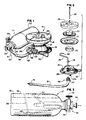
- the campstove includes a burner assembly 16, a fuel tank assembly 17, and a fuel hose or tube 18 which connects the fuel tank and the burner assembly.
- the burner assembly includes a base 19, a support collar 20, a burner pan 21, a burner 22, and a grate 23. The parts are clamped together by a bolt 24 and a nut 24a.
- a burner valve housing 25 is mounted on the base, and a generator tube 26 is connected to a threaded nipple 27 on the burner valve housing by a nut 28. The upper end of the generator tube is shaped to curve around the burner and terminates in a gas tip 29.
- An operating handle 30 is connected to a burner valve within the housing 25 for adjusting the size of the flame at the burner.
- the details of the burner assembly are conventional and well known.
- the fuel tank assembly 17 includes a fuel bottle 32 and a pump and valve assembly 33.
- the pump and valve assembly includes a housing 34 which screws into the fuel bottle, an operating knob 35 for opening and closing the valve, and a pump handle 36 for pumping air into the fuel bottle.
- a first tube 37 extends from the housing 34 at an angle to the axis of the fuel bottle and is connected to the pump.
- a second L-shaped tube 38 extends from the neck portion of the housing.
- the fuel tank assembly is designed for use when the fuel bottle is lying with its axis horizontal and the ends of the tubes 37 and 38 extend upwardly as illustrated in Fig. 3.
- the fuel level is indicated by the line 39, and the ends of the tubes 37 and 38 extend into the air space above the fuel.
- the L-shaped tube 38 includes an elbow 40 which is submerged in the fuel.
- a small orifice in the elbow permits fuel to flow through the tube when the valve is opened.
- the orifice in the elbow is larger than the orifice in the gas tip 29.
- the air space is pressurized by reciprocating the pump handle 37.
- the valve is opened by turning the knob 35, a mixture of fuel and air flows through the tube 38, past the valve, and into the connecting hose 18.
- the details of the pump and the valve are conventional and well known and need not be described herein.
- the fuel hose 18 includes a first end fitting 41 which is attached to the housing 34 and a restrictor assembly 42 on the other end which is adopted to connect to the burner valve 25 housing.
- the restrictor assembly includes a tubular probe 43 which has a tapered outer end 44, a cylindrical central portion 45, and a barbed inner end portion 46 which includes conical barbs 47. The barbs are sized to be frictionally retained within the internal bore 48 of the fuel hose.
- the particular fuel hose illustrated includes a rubber tube 49 and a woven outer sheath 50. After the barbed end of the probe is inserted into the rubber tube, a ferrule 51 is crimped over the end of the hose to secure the probe.
- a restrictor rod 53 extends through the bore of the probe.
- the diameter of the rod is slightly less than the internal diameter of the probe to provide an annular space 54 through which the fuel and air mixture can flow from the fuel hose to the burner.
- An O-ring seal 56 is mounted on the inside end of the restrictor rod and is retained by a nut 57 which is threaded onto the rod.
- a coil spring 58 is retained on the outer end of the rod by a nut 59. The inner end of the spring engages a shoulder 60 in the bore of the probe. The coil spring resiliently biases the O-ring against the inner end of the probe to seal the bore of the probe when the probe is not connected to the burner valve housing.
- a pair of L-shaped retaining clips 62 are pivotally mounted on a clip housing 63 which is mounted on the probe.
- Each clip includes a finger portion 64 and a jaw portion 65.
- the clips are pivotally mounted on pins 66 which extend through openings 67 in the clip housing.
- Springs 68 extend into openings 69 in the clip housing and resiliently bias the jaws 65 of the clip toward the probe.
- a tubular fitting 70 (Fig. 5) extends into an opening in burner valve housing 25 and is secured by brazing.
- a tubular probe fitting 71 is screwed into the fitting 70 and captures an O-ring 72 against a shoulder 73 within the fitting 70.
- a circumferential groove 74 in the probe fitting is sized to receive the jaws 65 of the probe clips 62.
- the fuel hose is connected to the burner assembly by inserting the probe 43 into the bore of the fitting 71.
- the restrictor rod 53 engages the burner valve housing 25
- the restrictor rod slides within the probe and compresses the spring 58.
- the O-ring 72 seals against the probe and prevents fuel from leaking through the fittings 70 and 71.
- the probe is releasably latched to the burner valve housing by pressing the finger portions 64 of the retaining clips 62 to permit the jaws 65 to clear the fitting 71.
- the finger portions are released when the jaws are aligned with the groove 74 in the fitting 71 (Fig. 5).
- the burner is lit by turning the flame adjusting handle 30 to the high position, holding a lighted match at the burner, and opening the fuel valve by turning the knob 35.
- a fuel/air mixture flows from the fuel bottle through the fuel hose.
- the restrictor rod 53 in the probe slows the flow of fuel/air to the burner and reduces the surge effect when the fuel valve is opened.
- the coil spring 58 also restricts the fuel/air flow. Minimizing the surge effect reduces the likelihood that the burner will be flooded with liquid fuel.
- the restrictor rod also reduces the amount of pressurized air which is lost from the fuel bottle during the initial fuel/air surge, thereby reducing the number of pumping strokes required for lighting and enhancing operator convenience.
- the pressure drop of the fuel/air mixture which is created by the restrictor rod also enhances the process of vaporizing the fuel.
- the portion of the fuel path before the restrictor rod is a high pressure region, and the portion of the fuel path between the restrictor rod and the orifice in the gas tip 29 is a low pressure region.
- the fuel/air mixture achieves partial vaporization in the low pressure region. This results in improved instant lighting, particularly at low temperatures.
- the flame adjuster handle 30 is then turned to adjust the flame to the desired heat.
- the restriction provided by the restrictor rod 53 and the coil spring 58 thereafter functions to reduce flame pulsation during burning.
- the spring-loaded restrictor rod and O-ring seal 56 provide a secondary shut-off which minimizes fuel leakage when the fuel hose is disconnected from the burner assembly.
- the coil spring moves the O-ring into sealing engagement with the inner end of the probe (Fig. 6). The fuel hose can therefore be disconnected from the burner for transporting the campstove without having residual fuel in the fuel hose drain from the hose.
- the internal diameter of the probe 43 was 1,57 mm (0,062 inch), and the diameter of the radially enlarged end of the bore provided by the shoulder 60 was 2,44 mm (0.096 inch).
- the diameter of the restrictor rod 53 was 1,27 mm (0,05 inch).
- the coil spring 58 was formed from 0,3 mm (0.012 inch) wire stainless steel and had an outside diameter of 2,24 mm (0.088 inch).
Landscapes
- Engineering & Computer Science (AREA)
- Chemical & Material Sciences (AREA)
- Combustion & Propulsion (AREA)
- Mechanical Engineering (AREA)
- General Engineering & Computer Science (AREA)
- Feeding And Controlling Fuel (AREA)
- Spray-Type Burners (AREA)
- Cookers (AREA)
Description
Claims (13)
- A liquid fuel burning appliance comprising:characterized bya burner assembly (16) including a burner (22) for providing a flame and a generator tube (26) in heat exchange relationship with the burner for vaporising liquid fuel within the generator tube,a fuel tank (17) separate from the burner for holding liquid fuel,a fuel valve (35) on the fuel tank,means (36) for pressurising the fuel tank with air,a fuel tube (18) connecting the fuel valve and the burner assembly for conveying pressurised liquid fuel and air to the burner assembly when the fuel valve is opened, the fuel tube having an upstream end which is connected to the fuel valve, a downstream end which is connected to the burner assembly, and an internal bore through which the fuel flows,flow-restricting means (53) positioned within the bore of the fuel tube adjacent the down stream end of the fuel tube for restricting the flow of fuel and air through the fuel tube, for reducing the pressure of the pressurised fuel downstream of the downstream end of the fuel tube, and for reducing surge of liquid fuel when the valve is open.
- The burner appliance of claim 1 in which said flow-restricting means includes a rod (53) within the bore.
- The burner appliance of claim 1 in which said flow-restricting means includes a tubular probe (43) having a bore and a first end which is inserted into the bore of the tube and a second end which is adapted to be connected to the burner assembly, and a rod (53) which is positioned within the bore of the probe.
- The burner appliance of claim 3 in which said rod is reciprocable within the bore of the probe and includes a first end which extends beyond the first end of the probe and a second end which extends beyond the second end of the probe, seal means (56) mounted on the first end of the rod for sealing the bore of the probe at the first end of the probe, and spring means (58) on the second end of the probe for resiliently biasing the seal means against the first end of the probe.
- The bumer appliance of claim 4 in which said spring means includes a coil spring (58) which is ensleeved on the second end of the rod and extends into the bore of the probe.
- The burner appliance of claim 4 in which said rod is reciprocable between a sealing position when the probe is disconnected from the burner assembly and an open position when the probe is connected to the burner assembly, the seal means engaging the first end of the probe when the rod is in the sealing position and being spaced from the first end of the probe when the rod is in the open position.
- The burner appliance of claim 6 including latch means (62) on the tube for releaseably latching the probe to the burner assembly.
- The burner appliance of claim 6 in which said burner assembly includes a tubular fitting (70) into which the second end of the probe can be inserted for connecting the tube to the burner assembly, the tubular fitting having a groove (74) which is engageable by said latch means.
- The burner appliance of claim 8 in which said latch means includes a pair of generally L-shaped clips (62) which are pivotally mounted on the probe, each of the clips including a finger portion (64) which extends generally parallel to the bore of the probe and a latching portion (65) which extends toward the probe generally perpendicularly to the finger portion, and spring means for resiliently biasing the latching portions toward the probe.
- The burner appliance of claim 4 in which said seal means comprises an O-ring (56) mounted on the first end of the rod.
- The burner appliance of claim 3 in which the first end of the probe includes barbs (47) for retaining the first end within the tube.
- The burner appliance of claim 3 in which said tube (18) is flexible.
- The burner appliance of claim 1 in which said tube (18) is flexible.
Applications Claiming Priority (2)
| Application Number | Priority Date | Filing Date | Title |
|---|---|---|---|
| US07/967,807 US5370527A (en) | 1992-10-28 | 1992-10-28 | Fuel tube for burner assembly with remote fuel tank |
| US967807 | 1992-10-28 |
Publications (3)
| Publication Number | Publication Date |
|---|---|
| EP0594964A2 EP0594964A2 (en) | 1994-05-04 |
| EP0594964A3 EP0594964A3 (en) | 1995-05-03 |
| EP0594964B1 true EP0594964B1 (en) | 1998-10-14 |
Family
ID=25513360
Family Applications (1)
| Application Number | Title | Priority Date | Filing Date |
|---|---|---|---|
| EP93113499A Expired - Lifetime EP0594964B1 (en) | 1992-10-28 | 1993-08-24 | Fuel tube for burner assembly with remote fuel tank |
Country Status (7)
| Country | Link |
|---|---|
| US (1) | US5370527A (en) |
| EP (1) | EP0594964B1 (en) |
| JP (1) | JP2740114B2 (en) |
| KR (1) | KR100188078B1 (en) |
| AU (1) | AU652311B2 (en) |
| CA (1) | CA2089804C (en) |
| DE (1) | DE69321551T2 (en) |
Families Citing this family (27)
| Publication number | Priority date | Publication date | Assignee | Title |
|---|---|---|---|---|
| US5605142A (en) * | 1994-04-04 | 1997-02-25 | Parker, Inc. | Portable barbeque |
| US5533891A (en) * | 1995-01-11 | 1996-07-09 | Uniweld Products, Inc. | Locking mechanism for hand torch regulators |
| NL9500068A (en) * | 1995-01-13 | 1996-08-01 | Meino Jan Van Der Woude | Baking table. |
| CA2194598A1 (en) * | 1996-08-12 | 1998-02-12 | Norris R. Long | Lpn canister connector for combustion appliance |
| US5868126A (en) * | 1996-08-12 | 1999-02-09 | The Coleman Company, Inc. | LPG canister connector for combustion appliance |
| US5983883A (en) * | 1996-12-10 | 1999-11-16 | Moulder; Charles R. | Mounting apparatus for portable stoves |
| WO1998026218A2 (en) * | 1996-12-10 | 1998-06-18 | Charles Robert Moulder | Mounting apparatus for portable stoves |
| USD422452S (en) * | 1997-07-14 | 2000-04-11 | Primus Ab | Cup for an open air stove |
| DE19745487C2 (en) * | 1997-10-15 | 2000-08-24 | Lorch J Ges & Co Kg | Handle for gas burners |
| US6257626B1 (en) * | 1999-04-27 | 2001-07-10 | Flow-Rite Controls, Ltd. | Connector for fluid handling system |
| US6250603B1 (en) * | 1999-11-24 | 2001-06-26 | Prime Solutions, Llc | Adjustable device for opening service valves |
| US6296228B1 (en) | 1999-11-24 | 2001-10-02 | Prime Solutions, Llc | Service device |
| WO2001057441A1 (en) * | 2000-01-31 | 2001-08-09 | Sharp Kabushiki Kaisha | Liquid fuel combustion device |
| US6223738B1 (en) * | 2000-08-28 | 2001-05-01 | Tsen-Tung Wu | Portable burner |
| AU2002357937A1 (en) | 2001-12-31 | 2003-07-24 | Prime Solutions, Llc | Coupling for servicing a pressurized system |
| US6699036B2 (en) | 2002-05-06 | 2004-03-02 | Weber-Stephen Products Company | Curvilinear burner tube |
| US6945774B2 (en) * | 2003-03-07 | 2005-09-20 | Weber-Stephen Products Co. | Gas burner with flame stabilization structure |
| US6899094B1 (en) * | 2003-11-26 | 2005-05-31 | Tsann Kuen Enterprise Co., Ltd. | Cooking assembly with a retaining clip for coupling first and second tubes thereof |
| DE102004007123B3 (en) * | 2004-02-12 | 2005-08-18 | Honeywell B.V. | Mixing device for mixing gas and combustion air for a gas burner comprises a gas regulating unit arranged on a monolithic unit consisting of a housing and a Venturi nozzle |
| US7150416B2 (en) * | 2004-04-09 | 2006-12-19 | Tronox Llc | Liquid fuel injection |
| US20070006868A1 (en) * | 2005-07-08 | 2007-01-11 | Joel Svedlund | Outdoor stove burner control |
| US20070087297A1 (en) * | 2005-10-17 | 2007-04-19 | The Coleman Company, Inc. | Liquid fuel backpacking stove |
| DE102009048405A1 (en) * | 2009-10-06 | 2011-04-07 | Honeywell Technologies S.A.R.L. | Control device for gas burners |
| DE102010010791A1 (en) * | 2010-03-09 | 2011-09-15 | Honeywell Technologies Sarl | Mixing device for a gas burner |
| EP2366953B1 (en) * | 2010-03-18 | 2016-06-15 | Electrolux Home Products Corporation N.V. | Gas cooking appliance |
| FR3017689B1 (en) * | 2014-02-17 | 2016-03-11 | Staubli Sa Ets | BAIONNETTE CONNECTOR SUITABLE FOR REMOVABLE JUNCTION OF PIPELINES |
| CN206073153U (en) * | 2016-08-12 | 2017-04-05 | 庞德制造有限公司 | It is quick to disconnect burning line |
Family Cites Families (24)
| Publication number | Priority date | Publication date | Assignee | Title |
|---|---|---|---|---|
| US1718473A (en) * | 1929-02-28 | 1929-06-25 | Coleman Lamp & Stove Co | Oil-burning device |
| US1858264A (en) * | 1929-11-07 | 1932-05-17 | Coleman Lamp & Stove Co | Device for burning liquid fuels |
| US1958400A (en) * | 1932-01-15 | 1934-05-08 | Boyd W Tullis | Vaporizing generator |
| US3648680A (en) * | 1970-11-19 | 1972-03-14 | Donald L Hein | Miniature camp stove |
| US3807687A (en) * | 1972-11-06 | 1974-04-30 | A Thompson | Automatic disconnect shut-off coupling for fluid lines |
| US3829278A (en) * | 1973-04-20 | 1974-08-13 | Penberthy Harvey Larry | Gasoline stove |
| US3900281A (en) * | 1973-04-20 | 1975-08-19 | Harvey Larry Penberthy | Backpacker's stove |
| US3876364A (en) * | 1973-07-12 | 1975-04-08 | Dennis V Hefling | Fuel control means for camp stoves |
| FR2371633A1 (en) * | 1976-11-19 | 1978-06-16 | Dupont S T | LIQUEFIED GAS APPLIANCE, ESPECIALLY GAS LIGHTER FOR SMOKERS |
| US4458719A (en) * | 1981-11-02 | 1984-07-10 | Imperial Clevite Inc. | Quick coupler service fitting |
| US4506695A (en) * | 1983-04-04 | 1985-03-26 | Scovill Inc. | Plastic tire valve |
| JPS60129614A (en) * | 1983-12-19 | 1985-07-10 | Omron Tateisi Electronics Co | Potentiometer |
| DE3403916A1 (en) * | 1984-02-04 | 1985-08-08 | Webasto-Werk W. Baier GmbH & Co, 8035 Gauting | HEATING UNIT, ESPECIALLY VEHICLE ADDITIONAL HEATING UNIT |
| US4613112A (en) * | 1985-07-19 | 1986-09-23 | Essex Industries, Inc. | Quick-disconnect fitting for gas line connection |
| IT209132Z2 (en) * | 1986-03-04 | 1988-09-12 | Bridgeport Brass Spa | VALVE IMPROVEMENTS FOR TUBELESS TIRES. |
| US4779608A (en) * | 1986-11-17 | 1988-10-25 | Smith T Randolph | Fireplace starter apparatus |
| JPH0661507B2 (en) * | 1987-07-24 | 1994-08-17 | トヨタ自動車株式会社 | Throttle valve for high viscosity paint |
| US5033777A (en) * | 1987-09-15 | 1991-07-23 | Colder Products Company | Male insert member having integrally molded part line free seal |
| US4886086A (en) * | 1987-12-23 | 1989-12-12 | Graco, Inc. | Non-degrading pressure regulator |
| US5027845A (en) * | 1989-08-07 | 1991-07-02 | Tuthill Corporation | Coupling with heat fusible actuator member |
| US5007448A (en) * | 1990-02-09 | 1991-04-16 | Advanced Commercial Products, Inc. | Filling device for liquid filled tires |
| US5123677A (en) * | 1990-05-31 | 1992-06-23 | Swagelok-Quick Connect Co. | All plastic quick-connect coupling |
| US5081847A (en) * | 1990-09-24 | 1992-01-21 | General Motors Corporation | Variable flow orifice tube |
| US5150880A (en) * | 1991-02-14 | 1992-09-29 | Austin Jr George K | Valve assembly with flow control |
-
1992
- 1992-10-28 US US07/967,807 patent/US5370527A/en not_active Expired - Lifetime
-
1993
- 1993-02-18 CA CA002089804A patent/CA2089804C/en not_active Expired - Lifetime
- 1993-03-10 AU AU34089/93A patent/AU652311B2/en not_active Ceased
- 1993-03-22 KR KR1019930004395A patent/KR100188078B1/en not_active Expired - Fee Related
- 1993-07-05 JP JP5165664A patent/JP2740114B2/en not_active Expired - Lifetime
- 1993-08-24 DE DE69321551T patent/DE69321551T2/en not_active Expired - Fee Related
- 1993-08-24 EP EP93113499A patent/EP0594964B1/en not_active Expired - Lifetime
Also Published As
| Publication number | Publication date |
|---|---|
| DE69321551T2 (en) | 1999-03-04 |
| JP2740114B2 (en) | 1998-04-15 |
| DE69321551D1 (en) | 1998-11-19 |
| EP0594964A2 (en) | 1994-05-04 |
| CA2089804C (en) | 1996-11-26 |
| JPH06207716A (en) | 1994-07-26 |
| EP0594964A3 (en) | 1995-05-03 |
| US5370527A (en) | 1994-12-06 |
| KR940009585A (en) | 1994-05-20 |
| AU3408993A (en) | 1994-05-19 |
| AU652311B2 (en) | 1994-08-18 |
| CA2089804A1 (en) | 1994-04-29 |
| KR100188078B1 (en) | 1999-06-01 |
Similar Documents
| Publication | Publication Date | Title |
|---|---|---|
| US5370527A (en) | Fuel tube for burner assembly with remote fuel tank | |
| US5417565A (en) | Automatic instant lighting system for liquid fuel burner | |
| US5803727A (en) | Burner assembly for burning appliances | |
| US20090280447A1 (en) | Backpacking stove | |
| US20070087297A1 (en) | Liquid fuel backpacking stove | |
| US6182651B1 (en) | Open air stove | |
| US3844270A (en) | Energy conversion system | |
| US4643164A (en) | Portable stove assembly | |
| US4432336A (en) | Energy conversion system | |
| US4353348A (en) | Energy conversion system | |
| US4197831A (en) | Energy conversion system | |
| US4025291A (en) | Energy conversion system | |
| US11499719B2 (en) | Regulator | |
| US675135A (en) | Fire-kindler. | |
| JP2674000B2 (en) | Vaporizer for gas appliances | |
| US2865443A (en) | Portable cooking stove | |
| US1671993A (en) | Fuel-oil preheating device | |
| KR830000157Y1 (en) | Preheating and ignition complex device of portable oil burner | |
| US2965164A (en) | Liquid fuel torches | |
| US650145A (en) | Hydrocarbon incandescent burner. | |
| US5188525A (en) | Fuel converter for gasoline powered lanterns | |
| CN2191367Y (en) | Self-driving burner | |
| US643363A (en) | Automatic gas-burner cut-off. | |
| US582619A (en) | canellopoulos | |
| CN2137764Y (en) | Liquified-gas stove with blue-flame while preheating and burning |
Legal Events
| Date | Code | Title | Description |
|---|---|---|---|
| PUAI | Public reference made under article 153(3) epc to a published international application that has entered the european phase |
Free format text: ORIGINAL CODE: 0009012 |
|
| AK | Designated contracting states |
Kind code of ref document: A2 Designated state(s): DE FR GB |
|
| PUAL | Search report despatched |
Free format text: ORIGINAL CODE: 0009013 |
|
| AK | Designated contracting states |
Kind code of ref document: A3 Designated state(s): DE FR GB |
|
| 17P | Request for examination filed |
Effective date: 19950831 |
|
| 17Q | First examination report despatched |
Effective date: 19970313 |
|
| GRAG | Despatch of communication of intention to grant |
Free format text: ORIGINAL CODE: EPIDOS AGRA |
|
| GRAG | Despatch of communication of intention to grant |
Free format text: ORIGINAL CODE: EPIDOS AGRA |
|
| GRAH | Despatch of communication of intention to grant a patent |
Free format text: ORIGINAL CODE: EPIDOS IGRA |
|
| GRAH | Despatch of communication of intention to grant a patent |
Free format text: ORIGINAL CODE: EPIDOS IGRA |
|
| GRAA | (expected) grant |
Free format text: ORIGINAL CODE: 0009210 |
|
| AK | Designated contracting states |
Kind code of ref document: B1 Designated state(s): DE FR GB |
|
| REF | Corresponds to: |
Ref document number: 69321551 Country of ref document: DE Date of ref document: 19981119 |
|
| ET | Fr: translation filed | ||
| PLBE | No opposition filed within time limit |
Free format text: ORIGINAL CODE: 0009261 |
|
| 26N | No opposition filed | ||
| PGFP | Annual fee paid to national office [announced via postgrant information from national office to epo] |
Ref country code: FR Payment date: 20010215 Year of fee payment: 8 |
|
| GBPC | Gb: european patent ceased through non-payment of renewal fee |
Effective date: 20000824 |
|
| REG | Reference to a national code |
Ref country code: GB Ref legal event code: 728V |
|
| REG | Reference to a national code |
Ref country code: GB Ref legal event code: IF02 |
|
| PG25 | Lapsed in a contracting state [announced via postgrant information from national office to epo] |
Ref country code: FR Free format text: LAPSE BECAUSE OF NON-PAYMENT OF DUE FEES Effective date: 20020430 |
|
| REG | Reference to a national code |
Ref country code: GB Ref legal event code: 728Y |
|
| REG | Reference to a national code |
Ref country code: FR Ref legal event code: ST |
|
| PGFP | Annual fee paid to national office [announced via postgrant information from national office to epo] |
Ref country code: DE Payment date: 20080829 Year of fee payment: 16 |
|
| PGFP | Annual fee paid to national office [announced via postgrant information from national office to epo] |
Ref country code: GB Payment date: 20080708 Year of fee payment: 16 |
|
| GBPC | Gb: european patent ceased through non-payment of renewal fee |
Effective date: 20090824 |
|
| PG25 | Lapsed in a contracting state [announced via postgrant information from national office to epo] |
Ref country code: DE Free format text: LAPSE BECAUSE OF NON-PAYMENT OF DUE FEES Effective date: 20100302 |
|
| PG25 | Lapsed in a contracting state [announced via postgrant information from national office to epo] |
Ref country code: GB Free format text: LAPSE BECAUSE OF NON-PAYMENT OF DUE FEES Effective date: 20090824 |