EP0594376B1 - Braking system for motors - Google Patents
Braking system for motors Download PDFInfo
- Publication number
- EP0594376B1 EP0594376B1 EP19930308255 EP93308255A EP0594376B1 EP 0594376 B1 EP0594376 B1 EP 0594376B1 EP 19930308255 EP19930308255 EP 19930308255 EP 93308255 A EP93308255 A EP 93308255A EP 0594376 B1 EP0594376 B1 EP 0594376B1
- Authority
- EP
- European Patent Office
- Prior art keywords
- brake
- motor
- resilient member
- configuration
- rotatable
- Prior art date
- Legal status (The legal status is an assumption and is not a legal conclusion. Google has not performed a legal analysis and makes no representation as to the accuracy of the status listed.)
- Expired - Lifetime
Links
Images

Classifications
-
- F—MECHANICAL ENGINEERING; LIGHTING; HEATING; WEAPONS; BLASTING
- F16—ENGINEERING ELEMENTS AND UNITS; GENERAL MEASURES FOR PRODUCING AND MAINTAINING EFFECTIVE FUNCTIONING OF MACHINES OR INSTALLATIONS; THERMAL INSULATION IN GENERAL
- F16D—COUPLINGS FOR TRANSMITTING ROTATION; CLUTCHES; BRAKES
- F16D55/00—Brakes with substantially-radial braking surfaces pressed together in axial direction, e.g. disc brakes
- F16D55/02—Brakes with substantially-radial braking surfaces pressed together in axial direction, e.g. disc brakes with axially-movable discs or pads pressed against axially-located rotating members
-
- F—MECHANICAL ENGINEERING; LIGHTING; HEATING; WEAPONS; BLASTING
- F16—ENGINEERING ELEMENTS AND UNITS; GENERAL MEASURES FOR PRODUCING AND MAINTAINING EFFECTIVE FUNCTIONING OF MACHINES OR INSTALLATIONS; THERMAL INSULATION IN GENERAL
- F16D—COUPLINGS FOR TRANSMITTING ROTATION; CLUTCHES; BRAKES
- F16D59/00—Self-acting brakes, e.g. coming into operation at a predetermined speed
-
- H—ELECTRICITY
- H02—GENERATION; CONVERSION OR DISTRIBUTION OF ELECTRIC POWER
- H02K—DYNAMO-ELECTRIC MACHINES
- H02K7/00—Arrangements for handling mechanical energy structurally associated with dynamo-electric machines, e.g. structural association with mechanical driving motors or auxiliary dynamo-electric machines
- H02K7/10—Structural association with clutches, brakes, gears, pulleys or mechanical starters
- H02K7/102—Structural association with clutches, brakes, gears, pulleys or mechanical starters with friction brakes
-
- F—MECHANICAL ENGINEERING; LIGHTING; HEATING; WEAPONS; BLASTING
- F16—ENGINEERING ELEMENTS AND UNITS; GENERAL MEASURES FOR PRODUCING AND MAINTAINING EFFECTIVE FUNCTIONING OF MACHINES OR INSTALLATIONS; THERMAL INSULATION IN GENERAL
- F16D—COUPLINGS FOR TRANSMITTING ROTATION; CLUTCHES; BRAKES
- F16D2127/00—Auxiliary mechanisms
- F16D2127/001—Auxiliary mechanisms for automatic or self-acting brake operation
- F16D2127/002—Auxiliary mechanisms for automatic or self-acting brake operation speed-responsive
-
- F—MECHANICAL ENGINEERING; LIGHTING; HEATING; WEAPONS; BLASTING
- F16—ENGINEERING ELEMENTS AND UNITS; GENERAL MEASURES FOR PRODUCING AND MAINTAINING EFFECTIVE FUNCTIONING OF MACHINES OR INSTALLATIONS; THERMAL INSULATION IN GENERAL
- F16D—COUPLINGS FOR TRANSMITTING ROTATION; CLUTCHES; BRAKES
- F16D2129/00—Type of operation source for auxiliary mechanisms
- F16D2129/04—Mechanical
- F16D2129/043—Weights
Definitions
- This invention relates to a brake for a motor, particularly a small motor such as is used in an electric lawnmower.
- Powered lawnmowers operate by providing one or more rapidly spinning or rotating blades to cut the vegetation. Even when the source of power is removed, the blade(s) continue to rotate or spin for some seconds. To reduce the risk of injury to the operator of the mower, there is a need to arrest the motion of the cutting blade(s) as quickly as possible.
- An electric motor with a ventable spring-loaded brake comprising a brake disc which is non-rotatably connected to the motor shaft but is axially movably arranged and may be pressed against the brake friction surface rigid with the casing, Wherein the brake disc is movable at least in one axial direction by an adjusting element operating as a function of centrifugal force, wherein the adjusting element comprises at least two pivotally mounted double-armed centrifugal force levers which are coupled to one another by at least one tension spring and are each articulated by their internal lever arm to the brake disc in such a way that the brake disc is axially movable in both directions by the adjusting element.
- the adjusting element comprises at least two pivotally mounted double-armed centrifugal force levers which are coupled to one another by at least one tension spring and are each articulated by their internal lever arm to the brake disc in such a way that the brake disc is axially movable in both directions by the adjusting element.
- a brake for a motor wherein a resilient member is rotatable with the motor and is deformable from a first conf guration to a second configuration as the centrifugal force on the resilient member increases from zero to a predetermined level, the biasing force of the resilient member thereby decreasing as the speed of the motor increases, the reduced biasing force releasing the brake and the brake being re-applied whenever the centrifugal force on the resilient member falls below the said predetermined level; characterised in that the resilient member is of a concave shape and comprises a plurality of members extending radially from the centre thereof such that, with the motor at rest, a first braking surface rotatable with the motor is urged by the resilient member into frictional contact with a non-rotatable second braking surface to apply a braking torque and, as the speed of the motor increases, the radially extending members are splayed outwards by centrifugal force thereby reducing the braking torque and
- the resilient member can be progressively deformable from its first configuration to its second configuration as the centrifugal force on the member increases, or it may deform abruptly when the force reaches a predetermined level and return to its original configuration when the force next falls below the predetermined level or a lower level.
- the tips of the radially extending members define the first braking surface and act directly upon the second braking surface to apply the brake.
- the first braking surface may comprise a brake disc carried by and rotatable with an armature spindle of the motor.
- the resilient member is preferably held on the armature spindle and urges the brake disc against a friction surface on the body of the motor.
- an electric motor including a brake as described above.
- Figure 1 shows a motor body (10) having an armature spindle (11) extending outwardly therefrom, and an annular friction pad (12) surrounding the armature spindle and adhesively bonded or otherwise secured to one end of the motor (10).
- the friction pad 12 is merely held against the end of the motor body 10 by gravity while co-operating ribs on the body 10 and pad 12 interlock with one another to prevent rotation of the pad.
- the friction pad 12 may comprise a plurality of discrete friction elements secured to the body (10) of the motor.
- a non-circular (shown as hexagonal) nut (14) is located along the armature spindle and rotates with the spindle.
- a brake disc (15) having at the centre thereof an aperture matching the shape of the nut (14) is located over the nut such that rotation of the spindle (11) also causes rotation of the brake disc (15).
- a spring (20) is located on the distal end of the armature spindle (11) and is secured in position by a clip (21) formed integrally with spring (20). In an alternative embodiment, not shown, the clip may be provided as a separate item. As the spindle rotates so does the spring (20).
- the spring (20) is substantially concave and comprises a plurality of members in the form of legs (23) extending radially outwards from a planar central portion (22) (as can be seen in Figure 2), each leg being angled relative to the plane of the central portion (22), thereby extending towards the brake disc (15) and, in the stationary state, making contact therewith.
- the tips (24) of the legs (23) of the spring (20) urge the brake disc (15) into face-to-face contact with the friction pad (12) to apply the brake.
- the motor armature rotates, thereby causing rotation of the nut (14), the brake disc (15), and the spring (20).
- the motor has sufficient torque to overcome the braking torque provided by the contact between the brake disc (15) and friction pad (12) and, as the rotational speed of the armature increases, the centrifugal force on each of the legs (23) causes corresponding movement of the legs from a rest position la to a splayed position 1b (Fig. 1).
- the force exerted by the spring (20) on the brake disc (15) is consequently reduced and produces a corresponding reduction of the braking torque.
- the brake disc is constrained to rotate with the nut, it is axially displaceable along the nut.
- the brake disc (15) is able to move axially away from the friction pad (12), the-eby releasing the brake completely.
- the motor (10) has particular application for rotating or reciprocating the cuttirg blade(s) in a lawnmower, hedgecut er or vegetation trimmer.
- the opposite end of the armatire spindle 11 drives the cutting blades, and the centrifugal brake ensures that the blades are rapidly brought to rest after the motor has been switched off.
- the nut (14) and brake disc (15) may be omitted.
- the legs (23) of spring (20) then act directly upon the friction surface (12) to apply the brake.
Landscapes
- Engineering & Computer Science (AREA)
- General Engineering & Computer Science (AREA)
- Mechanical Engineering (AREA)
- Power Engineering (AREA)
- Braking Arrangements (AREA)
- Connection Of Motors, Electrical Generators, Mechanical Devices, And The Like (AREA)
Description
- This invention relates to a brake for a motor, particularly a small motor such as is used in an electric lawnmower.
- Powered lawnmowers operate by providing one or more rapidly spinning or rotating blades to cut the vegetation. Even when the source of power is removed, the blade(s) continue to rotate or spin for some seconds. To reduce the risk of injury to the operator of the mower, there is a need to arrest the motion of the cutting blade(s) as quickly as possible.
- Many braking systems have been proposed for electric motors. One known device is described in German utility model number 8618334.6. An electric motor with a ventable spring-loaded brake is described comprising a brake disc which is non-rotatably connected to the motor shaft but is axially movably arranged and may be pressed against the brake friction surface rigid with the casing, Wherein the brake disc is movable at least in one axial direction by an adjusting element operating as a function of centrifugal force, wherein the adjusting element comprises at least two pivotally mounted double-armed centrifugal force levers which are coupled to one another by at least one tension spring and are each articulated by their internal lever arm to the brake disc in such a way that the brake disc is axially movable in both directions by the adjusting element. However, there is a need for a simple but effective braking mechanism that can be used on domestic lawnmowers.
- Accordingly, in one aspect of the present invention there is provided a brake for a motor wherein a resilient member is rotatable with the motor and is deformable from a first conf guration to a second configuration as the centrifugal force on the resilient member increases from zero to a predetermined level, the biasing force of the resilient member thereby decreasing as the speed of the motor increases, the reduced biasing force releasing the brake and the brake being re-applied whenever the centrifugal force on the resilient member falls below the said predetermined level; characterised in that the resilient member is of a concave shape and comprises a plurality of members extending radially from the centre thereof such that, with the motor at rest, a first braking surface rotatable with the motor is urged by the resilient member into frictional contact with a non-rotatable second braking surface to apply a braking torque and, as the speed of the motor increases, the radially extending members are splayed outwards by centrifugal force thereby reducing the braking torque and releasing the brake.
- The resilient member can be progressively deformable from its first configuration to its second configuration as the centrifugal force on the member increases, or it may deform abruptly when the force reaches a predetermined level and return to its original configuration when the force next falls below the predetermined level or a lower level.
- Preferably the tips of the radially extending members define the first braking surface and act directly upon the second braking surface to apply the brake.
- Alternatively, the first braking surface may comprise a brake disc carried by and rotatable with an armature spindle of the motor. In such an arrangement the resilient member is preferably held on the armature spindle and urges the brake disc against a friction surface on the body of the motor.
- In another aspect of the present invention there is provided an electric motor including a brake as described above.
- An embodiment of the present invention will now be described in greater detail with reference to the accompanying drawings in which:
- Figure 1 shows in cross-section an electric motor with a centrifugal brake embodying present invention; and
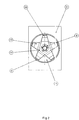
- Figure 2 shows an end view of the electric motor of Figure 1.
- Figure 1 shows a motor body (10) having an armature spindle (11) extending outwardly therefrom, and an annular friction pad (12) surrounding the armature spindle and adhesively bonded or otherwise secured to one end of the motor (10). In one alternative embodiment (not shown), the
friction pad 12 is merely held against the end of themotor body 10 by gravity while co-operating ribs on thebody 10 andpad 12 interlock with one another to prevent rotation of the pad. In a further alternative embodiment, thefriction pad 12 may comprise a plurality of discrete friction elements secured to the body (10) of the motor. - A non-circular (shown as hexagonal) nut (14) is located along the armature spindle and rotates with the spindle. A brake disc (15) having at the centre thereof an aperture matching the shape of the nut (14) is located over the nut such that rotation of the spindle (11) also causes rotation of the brake disc (15). A spring (20) is located on the distal end of the armature spindle (11) and is secured in position by a clip (21) formed integrally with spring (20). In an alternative embodiment, not shown, the clip may be provided as a separate item. As the spindle rotates so does the spring (20).
- The spring (20) is substantially concave and comprises a plurality of members in the form of legs (23) extending radially outwards from a planar central portion (22) (as can be seen in Figure 2), each leg being angled relative to the plane of the central portion (22), thereby extending towards the brake disc (15) and, in the stationary state, making contact therewith.
- At rest, the tips (24) of the legs (23) of the spring (20) urge the brake disc (15) into face-to-face contact with the friction pad (12) to apply the brake. When the power supply to the motor is switched on, the motor armature rotates, thereby causing rotation of the nut (14), the brake disc (15), and the spring (20). The motor has sufficient torque to overcome the braking torque provided by the contact between the brake disc (15) and friction pad (12) and, as the rotational speed of the armature increases, the centrifugal force on each of the legs (23) causes corresponding movement of the legs from a rest position la to a splayed position 1b (Fig. 1). The force exerted by the spring (20) on the brake disc (15) is consequently reduced and produces a corresponding reduction of the braking torque. Although the brake disc is constrained to rotate with the nut, it is axially displaceable along the nut. Thus, as the legs (23) of the spring splay outwards, the brake disc (15) is able to move axially away from the friction pad (12), the-eby releasing the brake completely.
- When the power to the motor is switched off the rotational speed of the motor armature is initially reduced by aerodynamic and internal frictional losses. This continues until the centrifugal force acting on the spring (20) is reduced sufficiently for the legs (23) of the spring to once again exert a force on the brake disc (15), forcing it back into contact with the friction pad (12) and thereby producing rapid braking of the motor.
- The motor (10) has particular application for rotating or reciprocating the cuttirg blade(s) in a lawnmower, hedgecut er or vegetation trimmer. In this case the opposite end of the
armatire spindle 11 drives the cutting blades, and the centrifugal brake ensures that the blades are rapidly brought to rest after the motor has been switched off. - In an alternative embodiment (not shown) the nut (14) and brake disc (15) may be omitted. The legs (23) of spring (20) then act directly upon the friction surface (12) to apply the brake.
Claims (7)
- A brake for a motor (10) wherein a resilient member (20) is rotatable with the motor and is deformable from a first configuration (1a) to a second configuration (1b) as the centrifugal force on the resilient member (20) increases from zero to a predetermined level, the biasing force of the resilient member (20) thereby decreasing as the speed of the motor increases, the reduced biasing force releasing the brake and the brake being re-applied whenever the centrifugal force on the resilient member (20) falls below the said predetermined level; characterised in that the resilient member (20) is of a concave shape and comprises a plurality of members (23) extending radially from the centre (22) thereof such that, with the motor it rest, a first braking surface (15, 24) rotatable with the motor (10) is urged by the resilient member (20) into frictional contact with a non-rotatable second braking surface (12) to apply a braking torque and, as the speed of the motor increases, the radially extending members (23) are splayed outwards by centrifugal force thereby reducing the braking torque and releasing the brake.
- A brake according to Claim 1 whereir the tips (24) of the radially extending members (23) define the first braking surface (15) and act directly on the second braking surface (12) to apply the brake.
- A brake according to claim 1 in which the first braking surface comprises a brake disc (15) carried by and rotatable with an armature spindle (11) of the motor.
- A brake according to claim 3 in which the resilient member (20) is held on the armature spindle and urges the brake disc (15) against a friction surface (12) on the body of the member (10).
- A brake according to any one of claims 1 to 4 wherein the resilient member (20) is progressively deformable from its first configuration to its second configuration as the centrifugal force on the member increases.
- A brake according to any one of claims 1 to 4 wherein the resilient member (20) deforms abruptly from its first configuration to its second configuration when the centrifugal force reaches a predetermined level and returns to its original configuration when the force next falls below the predetermined level or a lower level.
- An electric motor (10) comprising a rotatable armature spindle (11) and including a brake as claimed in any one of Claims 1 to 6, wherein the rotatable armature spindle carries the resilient member of the brake.
Applications Claiming Priority (2)
| Application Number | Priority Date | Filing Date | Title |
|---|---|---|---|
| GB929221876A GB9221876D0 (en) | 1992-10-19 | 1992-10-19 | Braking system for electric motors |
| GB9221876 | 1992-10-19 |
Publications (2)
| Publication Number | Publication Date |
|---|---|
| EP0594376A1 EP0594376A1 (en) | 1994-04-27 |
| EP0594376B1 true EP0594376B1 (en) | 1996-06-26 |
Family
ID=10723649
Family Applications (1)
| Application Number | Title | Priority Date | Filing Date |
|---|---|---|---|
| EP19930308255 Expired - Lifetime EP0594376B1 (en) | 1992-10-19 | 1993-10-15 | Braking system for motors |
Country Status (3)
| Country | Link |
|---|---|
| EP (1) | EP0594376B1 (en) |
| DE (1) | DE69303345T2 (en) |
| GB (1) | GB9221876D0 (en) |
Cited By (1)
| Publication number | Priority date | Publication date | Assignee | Title |
|---|---|---|---|---|
| EP3504954A1 (en) | 2017-12-27 | 2019-07-03 | Robert Bosch GmbH | Braking device |
Families Citing this family (3)
| Publication number | Priority date | Publication date | Assignee | Title |
|---|---|---|---|---|
| DE202004008714U1 (en) * | 2004-05-28 | 2004-07-29 | Dewert Antriebs- Und Systemtechnik Gmbh & Co Kg | Brake device for an electric drive motor and furniture |
| WO2013007962A2 (en) | 2011-07-13 | 2013-01-17 | Husqvarna Uk Limited | Brakes |
| CN114530986B (en) * | 2022-04-21 | 2022-07-05 | 南通领先电器有限公司 | Driving motor with brake function |
Family Cites Families (2)
| Publication number | Priority date | Publication date | Assignee | Title |
|---|---|---|---|---|
| US3038109A (en) * | 1959-12-09 | 1962-06-05 | Walt Inc De | Braking systems for electrical motors |
| DE8618334U1 (en) * | 1986-07-09 | 1987-11-12 | Siemens AG, 1000 Berlin und 8000 München | Electric motor with a ventilated spring pressure brake |
-
1992
- 1992-10-19 GB GB929221876A patent/GB9221876D0/en active Pending
-
1993
- 1993-10-15 EP EP19930308255 patent/EP0594376B1/en not_active Expired - Lifetime
- 1993-10-15 DE DE1993603345 patent/DE69303345T2/en not_active Expired - Lifetime
Cited By (1)
| Publication number | Priority date | Publication date | Assignee | Title |
|---|---|---|---|---|
| EP3504954A1 (en) | 2017-12-27 | 2019-07-03 | Robert Bosch GmbH | Braking device |
Also Published As
| Publication number | Publication date |
|---|---|
| DE69303345T2 (en) | 1996-11-28 |
| DE69303345D1 (en) | 1996-08-01 |
| GB9221876D0 (en) | 1992-12-02 |
| EP0594376A1 (en) | 1994-04-27 |
Similar Documents
| Publication | Publication Date | Title |
|---|---|---|
| US11419262B2 (en) | Grass trimmer | |
| US4466233A (en) | Mower drive assembly | |
| CN102042354B (en) | Brake assembly for power equipment | |
| US5549186A (en) | Clutch/brake assembly | |
| US20020095797A1 (en) | Bush cutting apparatus | |
| EP3833519B1 (en) | Hair cutting appliance | |
| CN101467507B (en) | Brake device of garden tools | |
| JP2880135B2 (en) | Torque limiting fitting | |
| US4189284A (en) | Slipping clutch mechanism | |
| EP0594376A1 (en) | Braking system for motors | |
| US4158944A (en) | Rotary blade coupling for lawn mower | |
| CN201182102Y (en) | Brake device of garden tools | |
| GB2284642A (en) | A machine comprising a rotating part braked when its speed falls below a defined value | |
| CN218868748U (en) | Riding type mower with reverse gear cutting prevention device | |
| CN109980844B (en) | brake equipment | |
| GB2192252A (en) | Improvements in or relating to braking mechanisms | |
| CA3118539A1 (en) | Modular power unit and tool using a modular power unit | |
| US4294339A (en) | Clutch assembly | |
| JPS5948602B2 (en) | Vegetation cutting device | |
| CN108174693B (en) | Garden Tools | |
| JPH02286006A (en) | Overrotation prevention device for power cutter | |
| RU2059109C1 (en) | Wind motor | |
| CN215421681U (en) | Lawn mower of gear drive mechanical brake | |
| EP0620964A1 (en) | Improvements in and relating to a clutch and brake assembly | |
| CN223613863U (en) | A pulley mechanism with braking device for a lawnmower |
Legal Events
| Date | Code | Title | Description |
|---|---|---|---|
| PUAI | Public reference made under article 153(3) epc to a published international application that has entered the european phase |
Free format text: ORIGINAL CODE: 0009012 |
|
| AK | Designated contracting states |
Kind code of ref document: A1 Designated state(s): DE FR GB IT NL |
|
| 17P | Request for examination filed |
Effective date: 19941003 |
|
| 17Q | First examination report despatched |
Effective date: 19950222 |
|
| GRAH | Despatch of communication of intention to grant a patent |
Free format text: ORIGINAL CODE: EPIDOS IGRA |
|
| GRAA | (expected) grant |
Free format text: ORIGINAL CODE: 0009210 |
|
| RAP1 | Party data changed (applicant data changed or rights of an application transferred) |
Owner name: ATCO-QUALCAST LIMITED |
|
| AK | Designated contracting states |
Kind code of ref document: B1 Designated state(s): DE FR GB IT NL |
|
| PG25 | Lapsed in a contracting state [announced via postgrant information from national office to epo] |
Ref country code: NL Free format text: LAPSE BECAUSE OF FAILURE TO SUBMIT A TRANSLATION OF THE DESCRIPTION OR TO PAY THE FEE WITHIN THE PRESCRIBED TIME-LIMIT Effective date: 19960626 Ref country code: IT Free format text: LAPSE BECAUSE OF FAILURE TO SUBMIT A TRANSLATION OF THE DESCRIPTION OR TO PAY THE FEE WITHIN THE PRESCRIBED TIME-LIMIT;WARNING: LAPSES OF ITALIAN PATENTS WITH EFFECTIVE DATE BEFORE 2007 MAY HAVE OCCURRED AT ANY TIME BEFORE 2007. THE CORRECT EFFECTIVE DATE MAY BE DIFFERENT FROM THE ONE RECORDED. Effective date: 19960626 |
|
| REF | Corresponds to: |
Ref document number: 69303345 Country of ref document: DE Date of ref document: 19960801 |
|
| ET | Fr: translation filed | ||
| NLV1 | Nl: lapsed or annulled due to failure to fulfill the requirements of art. 29p and 29m of the patents act | ||
| PLBE | No opposition filed within time limit |
Free format text: ORIGINAL CODE: 0009261 |
|
| 26N | No opposition filed | ||
| REG | Reference to a national code |
Ref country code: GB Ref legal event code: IF02 |
|
| PGFP | Annual fee paid to national office [announced via postgrant information from national office to epo] |
Ref country code: FR Payment date: 20121113 Year of fee payment: 20 |
|
| PGFP | Annual fee paid to national office [announced via postgrant information from national office to epo] |
Ref country code: GB Payment date: 20121023 Year of fee payment: 20 |
|
| PGFP | Annual fee paid to national office [announced via postgrant information from national office to epo] |
Ref country code: DE Payment date: 20121217 Year of fee payment: 20 |
|
| REG | Reference to a national code |
Ref country code: DE Ref legal event code: R071 Ref document number: 69303345 Country of ref document: DE |
|
| REG | Reference to a national code |
Ref country code: GB Ref legal event code: PE20 Expiry date: 20131014 |
|
| PG25 | Lapsed in a contracting state [announced via postgrant information from national office to epo] |
Ref country code: DE Free format text: LAPSE BECAUSE OF EXPIRATION OF PROTECTION Effective date: 20131016 Ref country code: GB Free format text: LAPSE BECAUSE OF EXPIRATION OF PROTECTION Effective date: 20131014 |