EP0593793B1 - Stimulators for fuel combustion - Google Patents
Stimulators for fuel combustion Download PDFInfo
- Publication number
- EP0593793B1 EP0593793B1 EP92117699A EP92117699A EP0593793B1 EP 0593793 B1 EP0593793 B1 EP 0593793B1 EP 92117699 A EP92117699 A EP 92117699A EP 92117699 A EP92117699 A EP 92117699A EP 0593793 B1 EP0593793 B1 EP 0593793B1
- Authority
- EP
- European Patent Office
- Prior art keywords
- fuel
- water
- high pressure
- combustion
- pipe
- Prior art date
- Legal status (The legal status is an assumption and is not a legal conclusion. Google has not performed a legal analysis and makes no representation as to the accuracy of the status listed.)
- Expired - Lifetime
Links
Images


Classifications
-
- F—MECHANICAL ENGINEERING; LIGHTING; HEATING; WEAPONS; BLASTING
- F02—COMBUSTION ENGINES; HOT-GAS OR COMBUSTION-PRODUCT ENGINE PLANTS
- F02M—SUPPLYING COMBUSTION ENGINES IN GENERAL WITH COMBUSTIBLE MIXTURES OR CONSTITUENTS THEREOF
- F02M25/00—Engine-pertinent apparatus for adding non-fuel substances or small quantities of secondary fuel to combustion-air, main fuel or fuel-air mixture
- F02M25/022—Adding fuel and water emulsion, water or steam
- F02M25/0228—Adding fuel and water emulsion
-
- F—MECHANICAL ENGINEERING; LIGHTING; HEATING; WEAPONS; BLASTING
- F02—COMBUSTION ENGINES; HOT-GAS OR COMBUSTION-PRODUCT ENGINE PLANTS
- F02B—INTERNAL-COMBUSTION PISTON ENGINES; COMBUSTION ENGINES IN GENERAL
- F02B47/00—Methods of operating engines involving adding non-fuel substances or anti-knock agents to combustion air, fuel, or fuel-air mixtures of engines
- F02B47/02—Methods of operating engines involving adding non-fuel substances or anti-knock agents to combustion air, fuel, or fuel-air mixtures of engines the substances being water or steam
-
- F—MECHANICAL ENGINEERING; LIGHTING; HEATING; WEAPONS; BLASTING
- F02—COMBUSTION ENGINES; HOT-GAS OR COMBUSTION-PRODUCT ENGINE PLANTS
- F02M—SUPPLYING COMBUSTION ENGINES IN GENERAL WITH COMBUSTIBLE MIXTURES OR CONSTITUENTS THEREOF
- F02M25/00—Engine-pertinent apparatus for adding non-fuel substances or small quantities of secondary fuel to combustion-air, main fuel or fuel-air mixture
- F02M25/022—Adding fuel and water emulsion, water or steam
- F02M25/0221—Details of the water supply system, e.g. pumps or arrangement of valves
- F02M25/0225—Water atomisers or mixers, e.g. using ultrasonic waves
-
- F—MECHANICAL ENGINEERING; LIGHTING; HEATING; WEAPONS; BLASTING
- F02—COMBUSTION ENGINES; HOT-GAS OR COMBUSTION-PRODUCT ENGINE PLANTS
- F02M—SUPPLYING COMBUSTION ENGINES IN GENERAL WITH COMBUSTIBLE MIXTURES OR CONSTITUENTS THEREOF
- F02M25/00—Engine-pertinent apparatus for adding non-fuel substances or small quantities of secondary fuel to combustion-air, main fuel or fuel-air mixture
- F02M25/022—Adding fuel and water emulsion, water or steam
- F02M25/032—Producing and adding steam
- F02M25/038—Producing and adding steam into the cylinder or the pre-combustion chamber
-
- F—MECHANICAL ENGINEERING; LIGHTING; HEATING; WEAPONS; BLASTING
- F02—COMBUSTION ENGINES; HOT-GAS OR COMBUSTION-PRODUCT ENGINE PLANTS
- F02B—INTERNAL-COMBUSTION PISTON ENGINES; COMBUSTION ENGINES IN GENERAL
- F02B1/00—Engines characterised by fuel-air mixture compression
- F02B1/02—Engines characterised by fuel-air mixture compression with positive ignition
- F02B1/04—Engines characterised by fuel-air mixture compression with positive ignition with fuel-air mixture admission into cylinder
-
- F—MECHANICAL ENGINEERING; LIGHTING; HEATING; WEAPONS; BLASTING
- F02—COMBUSTION ENGINES; HOT-GAS OR COMBUSTION-PRODUCT ENGINE PLANTS
- F02B—INTERNAL-COMBUSTION PISTON ENGINES; COMBUSTION ENGINES IN GENERAL
- F02B3/00—Engines characterised by air compression and subsequent fuel addition
- F02B3/06—Engines characterised by air compression and subsequent fuel addition with compression ignition
-
- Y—GENERAL TAGGING OF NEW TECHNOLOGICAL DEVELOPMENTS; GENERAL TAGGING OF CROSS-SECTIONAL TECHNOLOGIES SPANNING OVER SEVERAL SECTIONS OF THE IPC; TECHNICAL SUBJECTS COVERED BY FORMER USPC CROSS-REFERENCE ART COLLECTIONS [XRACs] AND DIGESTS
- Y02—TECHNOLOGIES OR APPLICATIONS FOR MITIGATION OR ADAPTATION AGAINST CLIMATE CHANGE
- Y02T—CLIMATE CHANGE MITIGATION TECHNOLOGIES RELATED TO TRANSPORTATION
- Y02T10/00—Road transport of goods or passengers
- Y02T10/10—Internal combustion engine [ICE] based vehicles
- Y02T10/12—Improving ICE efficiencies
Definitions
- Burning stimulators comprise:
- Stimulators for fuel combustion are designed to be used in engineering for:
- Fuel oil has so far been injected by a high pressure fuel pump through a fuel valve directly into the cylinder of the diesel engine or other combustion chambers. Recently, however, there has been a tendency of water injection into the diesel engine cylinder. This method has been successfully applied by the British EMULSA system. This system provided the injection of the emulsion consisting of water and fuel oil into the diesel engine cylinder.
- a fuel combustion stimulating device comprising a high pressure water pump for supplying a high pressurized water and a high pressure superheater for heating said high pressurized water.
- the embodiment disclosed in this document a Otto-engine with a carburetor.
- each cylinder is provided with an intake port for a fuel-air mixture and, on the other hand, there is a valve means for injecting the superheated water into the engine.
- This valve means comprises a port for suppliance of a control oil for controlling the timing and duration of the injection of superheated water.
- the device can also be employed within a diesel engine. In this case, one opening in the above mentioned valve means is used for the insertion of an additional fuel injection valve instead of a spark plug which has been inserted therein in case of an Otto-engine.
- the installation designed provides the use of the water over the critical state, superheated prior to injection into the combustion chamber of the diesel engine, gas turbine, steam boilers or other large industrial combustion installations. Superheated in this way, the water will remain liquid as long as it is in the critical state, thereby keeping its highly accumulated thermal energy.
- the newly designed dual injector according to claim 1 provides a simultaneous and separate injection of fuel oil and superheated water.
- the dual injector must conform to the normal running conditions of the engine, even if the engine should operate with its superheated water supply being disconnected.
- the main burning stimulator is the superheated water in the critical state, while a further improvement of another fuel combustion stimulator is electricity conducted through electrodes into the combustion chamber in the form of an electric spark, lightnings or arc, acting on superheated water particles at a very high temperature, much higher than the temperature caused by the burning of the fuel. Acting on drops of water with high enthalpy, both thermally and electrically, the electric spark, lightnings and arc will increase the ionisation in the cylinder in order to dissolve the water drops into their molecular and atomic components for enhanced burning and microexplosions.
- Both stimulators i.e. water in the critical state and the electrical stimulation, could be in use at the same time.
- Electrical stimulators produced and prepared outside the combustion chamber and connected by electrodes with the cylinder or the other combustion chambers, should provide the normal running operation of the diesel engine or any other installation even with the electricity supply disconnected.
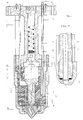
- Dual injector (DI) in Fig. 4 shows the direct injection unit, designed to be applied in diesel engines, gas turbines, steam boilers and other power installations, respectively.
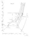
- Fig. 1 T-S diagram illustrates the relation between the change in the water condition when injected by the EMULSA system and when injected by the WICS system.
- Curve “b” shows the EMULSA system.
- cold water is preheated up to 120°C prior to injection and partly evaporates into the diesel engine cylinder after the injection, during the lag time of 0.05 sec., which is at disposal for evaporation and superheating before the fuel ignition.
- the steam produced in this way reduces microexplosions and has the fireextinguishing effects on flame.
- Fig. 2 illustrates the assembled installation design for diesel engine application consisting of the following main parts:
- FP high pressure fuel pump
- High pressure multipiston water pump equipped with the unit for easy capacity control and driven by diesel engine or directly coupled with the electric motor (E), regardless of injection timing, supplies water (W) of about 60°C into a common high pressure electric water superheater (EWS) under constant pressure over 230 bars and superheated to 400°C. From the superheater WICS is distributed to each dual injector (DI) fitted in each cylinder cover of the diesel engine. Timing of water injection is simultaneous with and piloted by the fuel injection timing, but the quantity of water injected into the cylinder is constant and limited with the inlet diameter in the nozzle cap.
- DI dual injector
- Dual injector is designed to provide the continuous engine operation if WICS / electric stimulators are disconnected from the power supply.
- a pair of electrodes is installed for electrical stimulation of fuel combustion, Claim 2.
- Fig. 3 illustrates a high pressure electric water superheater (EWS), consisting of the following parts: high pressure pipes (1) and (2) welded to one inlet and one outlet duct (3) fully inserted into a casting mould box (7) in such a way that pipes (1) pass waterproofly through the bottom of the casting mould box. In the same way between the pipes (2) are inserted pockets (5) for heating elements (6). After that the mould box is filled with the liquid cast metal (4) (brass, lead, aluminium or another alloy) in order to serve as a heat transfer medium from heating elements to the water.
- the water superheater is completely thermally insulated (8) from outside and equipped with control and measuring instruments. Pipes (1) on inlet and outlet side have fitted pipe connections for the easy replacement of the heater. Pipes from the superheater to dual injectors are thermally insulated too.
- Fig. 4 illustrates a dual injector (DI), for the injection of fuel oil and superheated water in the critical state into the combustion chamber. It consists of the following parts: the fuel oil inlet pipe (F) bypasses the injector body (1) and is connected to the nozzle (3), (see detail 12) or welded to the top surface of the nozzle. Water pipe (W) also bypasses the body (1) and the machined part of the nozzle (3) and is connected with it (as in detail 12) or welded. On its outer side the pipe is additionally insulated and encapsulated with a special porcelaine or china clay tube (11). The body (1), the nozzle (3) and the nozzle cap (4) are fastened together with the cap nut (5).
- DI dual injector
- the pressure of the fuel oil valve opening is adjusted with a bolt (10) via a spring (9), a thrust piece (8), a thrust pin (7) presses the needle (2).
- the nozzle cap (4) has separate channels, one for fuel oil and another for WICS. In order to reduce heat transfer from water to the fuel oil, between the channels in the nozzle cap there is some empty space. Pins (6) fix joint parts and protect them when tightening. Needle (2) lifts stroke "X" with the fuet oil impulse, opening both channels at the same time, and fuel oil and water are injected simultaneously into the diesel engine cylinder or into another combustion chamber.
- Electric combustion stimulators arc implemented with electrodes installed close to dual injection tip, through which electricity is conducted - sparking, lightnings or arc being produced in separate electric machinery outside the engine and the combustion space.
- the intensity of the sparking and lightnings are much stronger than the ignition spark used in Otto engines. The two cannot even be compared, since an electric spark is not necessary for diesel engine ignition.
- Very high temperature of sparking, lightnings and arc is much higher than the temperature produced by fuel flame during fuel ignition in the cylinder (abt. 2400° K).
- Electrical stimulators for combustion in gas turbines, boilers and other combustion chambers are built in basically the same way.
- Lightning is produced in Tesla inductor.
- Sparking is produced in transformers with primary and secondary coils in resonance, and sparking is a function of oscillation.
- Electric arc produced for this purpose will be based on technology in practice. Such electrical stimulation should provide a continuous supply of electricity, both with the pulse system of fuel oil supply and with the continuous pressure system fuel oil supply.
Landscapes
- Engineering & Computer Science (AREA)
- Chemical & Material Sciences (AREA)
- Combustion & Propulsion (AREA)
- Mechanical Engineering (AREA)
- General Engineering & Computer Science (AREA)
- Health & Medical Sciences (AREA)
- Public Health (AREA)
- Water Supply & Treatment (AREA)
- Fuel-Injection Apparatus (AREA)
Description
- Heavy marine diesel engines for ship propulsion and for land-based diesel power plants installations,
- Gas turbines
- Steam boilers driven by any kind of fuel
- Other large industrial fuel consumers.
- high pressure fuel oil pump (FP)
- high pressure water supply pump (WP)
- high pressure electric water superheater (EWS)
- dual injector (DI)
Claims (8)
- Fuel combustion stimulating device comprisingcharacterized in thata high pressure water pump (WP) for supplying a high pressurized water,a high pressure superheater (EWS) for heating said high pressurized water,a dual injector valve and a fuel pump supplying fuel to said dual injector valve,said dual injector valve comprisinga fuel delivery pipe (F) anda separate water delivery pipe (W),said high pressure water pump is a multicylinder high pressure water pump (WP) pressurizing the water up to at least 230 bars,said high pressure superheater (EWS) is a high pressure electric water superheater heating the water up to at least 400°C so that the water is brought into the critical state before entering the dual injector valvesaid dual injector valve further comprises a dual injector needle device (2) which is adapted to perform a simultaneous injection of the fuel and the superheated water into a combustion chamber through separate nozzle ports.
- Fuel combustion stimulating device according to claim 1,
characterized by
electrical stimulators based on sparking, lightnings or electric arc by means of a pair of electrodes installed on each cylinder cover of a combustion chamber close to the tip of said dual injector valve. - Fuel combustion stimulating device according to claim 2,
characterized in that
in one electrode block of said pair of electrodes several conductors are installed for each spark, lightning or electric arc, to which terminals from each generator machine are connected. - Fuel combustion stimulating device according to claim 1,
characterized in that said high pressure superheater (EWS) comprisespipes (1, 2) being welded to one inlet and one outlet tube duct (3) and fully inserted into a casting mould box (7),pockets (5) for electric heating elements (6) being located between said pipes (2), whereby all inlet pipes (1) pass watertightly water through the bottom of said mould box (7), whereby, after inserting the pipe construction, said mould box (7) is filled with molten metal (4) like brass, aluiminum, lead or other alloys to be used as heat transfer medium from heating elements to said metal and from said metal to the water, whereby said superheater (EWS) and said pipes outside are thermally insulated (8) and equipped with control and measuring instruments, while inlet and outlet pipes are furnished with tube connections for easy replacement of the heater. - Fuel combustion stimulating device according to claim 1,
characterized in that said dual injector valve comprisesa valve body (1),a fuel pipe (F) bypassing said body (1) and connected or being welded to an upper surface of a nozzle (3) being inserted in said body (1),said body (1), said nozzle (3), a needle (2), a nozzle cap (4) and a center pin (6) being fastened together with a cap nut (5),a bolt (10) for setting a fuel pressure via a spring (9), a thrust piece (8), a thrust pin (7) and said needle (2),a water pipe (W) on the opposite side of said fuel pipe (F) bypassing said body (1) and a partly machined side of said nozzle (3), whereby said water pipe (W) being connected or welded on a lower side of said nozzle (3),whereby said water pipe (W) is additionally insulated with a pipe (11) of china clay, andsaid nozzle cap (4) has separate channels, one for fuel and another for superheated water in the critical state, between the channels there is an empty space in order to insulate heat transfer from the water to the fuel, andsaid needle (2) is raisable about a distance "X", opening both channels at once caused by a fuel impulse from a high pressure fuel pump,whereby timing of superheated water in the critical state is piloted by the simultaneous setting of the fuel pump timing. - Fuel combustion stimulating device according to any of the preceeding claims, characterized in that
it is applicable in gas turbine combustion chambers, in which case a gear fuel oil pump is provided for a constant pressure delivery instead of said high pressure fuel oil pump (FP). - Fuel combustion stimulating device according to any of the preceeding claims, characterized in that
it is applicable in steam boilers, whereby, when coal powder is used for burning in the combustion chamber, initial heating of the boiler may be performed with fuel oil and, after that, the fuel oil pipe may be used for water supply to said dual injector valve, so that said dual injector valve should be adapted for different kinds of fuel. - Fuel combustion stimulating device according to any of the preceeding claims, characterized in that
it is applicable in all industrial equipments using combustion chambers with large fuel consumption being adapted thereto.
Priority Applications (3)
| Application Number | Priority Date | Filing Date | Title |
|---|---|---|---|
| EP92117699A EP0593793B1 (en) | 1992-10-19 | 1992-10-19 | Stimulators for fuel combustion |
| DE69223968T DE69223968T2 (en) | 1992-10-19 | 1992-10-19 | Combustion fuel stimulators |
| DK92117699T DK0593793T3 (en) | 1992-10-19 | 1992-10-19 | Fuel Combustion Stimulators |
Applications Claiming Priority (1)
| Application Number | Priority Date | Filing Date | Title |
|---|---|---|---|
| EP92117699A EP0593793B1 (en) | 1992-10-19 | 1992-10-19 | Stimulators for fuel combustion |
Publications (2)
| Publication Number | Publication Date |
|---|---|
| EP0593793A1 EP0593793A1 (en) | 1994-04-27 |
| EP0593793B1 true EP0593793B1 (en) | 1998-01-07 |
Family
ID=8210138
Family Applications (1)
| Application Number | Title | Priority Date | Filing Date |
|---|---|---|---|
| EP92117699A Expired - Lifetime EP0593793B1 (en) | 1992-10-19 | 1992-10-19 | Stimulators for fuel combustion |
Country Status (3)
| Country | Link |
|---|---|
| EP (1) | EP0593793B1 (en) |
| DE (1) | DE69223968T2 (en) |
| DK (1) | DK0593793T3 (en) |
Cited By (4)
| Publication number | Priority date | Publication date | Assignee | Title |
|---|---|---|---|---|
| WO2001004477A1 (en) | 1999-07-07 | 2001-01-18 | Boric Miroslav | High-pressure gas-turbine plant using high-pressure piston-type compressor |
| WO2002081602A1 (en) * | 2001-04-09 | 2002-10-17 | Supercritical Combustion Corporation | Heating of fuels |
| US6520767B1 (en) | 1999-04-26 | 2003-02-18 | Supercritical Combusion Corporation | Fuel delivery system for combusting fuel mixtures |
| WO2004007933A2 (en) * | 2002-07-16 | 2004-01-22 | Nicholas Mark Brown | Configuration and method for operating an engine |
Families Citing this family (8)
| Publication number | Priority date | Publication date | Assignee | Title |
|---|---|---|---|---|
| US6010544A (en) * | 1997-12-18 | 2000-01-04 | Quantum Energy Technologies | Supercritical water fuel composition and combustion system |
| US6170441B1 (en) * | 1998-06-26 | 2001-01-09 | Quantum Energy Technologies | Engine system employing an unsymmetrical cycle |
| KR20010008168A (en) * | 2000-11-13 | 2001-02-05 | 박권하 | Water mixing unit of diesel engine using water/oil emulsified fuel |
| JP3902018B2 (en) * | 2001-04-06 | 2007-04-04 | 三菱重工業株式会社 | Method and system for operating a reciprocating internal combustion engine |
| CN1461377A (en) * | 2001-04-06 | 2003-12-10 | 三菱重工业株式会社 | Method of operating internal combustion engine injected with critical water |
| DE102008006953B4 (en) * | 2008-01-31 | 2010-09-02 | Airbus Deutschland Gmbh | System and method for reducing pollutants in engine exhaust |
| DE102017204130A1 (en) | 2017-03-13 | 2018-09-13 | Robert Bosch Gmbh | Water injection device and method for operating a water injection device |
| DE102018001246A1 (en) * | 2018-02-18 | 2019-08-22 | Gofficient Ug | Internal combustion engine with direct injection by exhaust heat generated steam |
Family Cites Families (5)
| Publication number | Priority date | Publication date | Assignee | Title |
|---|---|---|---|---|
| US3180324A (en) * | 1963-05-03 | 1965-04-27 | Omer J Stone | Engine |
| JPS5194034A (en) * | 1975-02-17 | 1976-08-18 | ||
| GB1541056A (en) * | 1976-03-26 | 1979-02-21 | Energiagazdalkodasi Intezet | Internal combustion engines |
| PH19563A (en) * | 1980-10-14 | 1986-05-21 | Schlueter William Bryan | System and method for superheated-water injection system (swis) |
| DE4040235A1 (en) * | 1990-12-15 | 1992-06-17 | Bosch Gmbh Robert | Injection pump for diesel engine - has work chamber of pump piston limited by dividing piston on same axis as pump piston |
-
1992
- 1992-10-19 DK DK92117699T patent/DK0593793T3/en active
- 1992-10-19 DE DE69223968T patent/DE69223968T2/en not_active Expired - Fee Related
- 1992-10-19 EP EP92117699A patent/EP0593793B1/en not_active Expired - Lifetime
Cited By (4)
| Publication number | Priority date | Publication date | Assignee | Title |
|---|---|---|---|---|
| US6520767B1 (en) | 1999-04-26 | 2003-02-18 | Supercritical Combusion Corporation | Fuel delivery system for combusting fuel mixtures |
| WO2001004477A1 (en) | 1999-07-07 | 2001-01-18 | Boric Miroslav | High-pressure gas-turbine plant using high-pressure piston-type compressor |
| WO2002081602A1 (en) * | 2001-04-09 | 2002-10-17 | Supercritical Combustion Corporation | Heating of fuels |
| WO2004007933A2 (en) * | 2002-07-16 | 2004-01-22 | Nicholas Mark Brown | Configuration and method for operating an engine |
Also Published As
| Publication number | Publication date |
|---|---|
| EP0593793A1 (en) | 1994-04-27 |
| DK0593793T3 (en) | 1998-09-07 |
| DE69223968D1 (en) | 1998-02-12 |
| DE69223968T2 (en) | 1998-05-28 |
Similar Documents
| Publication | Publication Date | Title |
|---|---|---|
| US4332223A (en) | Plasma fuel ignitors | |
| EP0778410B1 (en) | Injection valve arrangement for an internal combustion engine | |
| EP0593793B1 (en) | Stimulators for fuel combustion | |
| US6955154B1 (en) | Fuel injector spark plug | |
| US5715788A (en) | Integrated fuel injector and ignitor assembly | |
| AU653129B2 (en) | Method of combustion for dual fuel engine | |
| US5085176A (en) | Method of and apparatus for generating and injecting hydrogen into an engine | |
| DE69534203D1 (en) | CHARGING PREPARATION PLANT FOR ENABLING COLD STARTING AND WARMING UP IN THE FOREIGN MIXED INTERNAL PISTON MILLING MACHINE | |
| US5237964A (en) | Internal combustion engine with a new sequence of operation and combustion | |
| US20010050069A1 (en) | Direct fuel injection and ignition system for internal combustion engines | |
| CA1185798A (en) | Internal expansion engine | |
| EP0848786B1 (en) | A device for integrated injection and ignition in an internal combustion engine | |
| GB2074229A (en) | Diesel engine with fuel injector | |
| CA2264655A1 (en) | Fuel injection device for an internal combustion engine | |
| CN112752902A (en) | Injector and method for injecting fuel and additional fluid, and use of an injector | |
| US4558664A (en) | Superheated fuel injection for combustion of liquid-solid slurries | |
| AU720373B2 (en) | Liquid gas engine | |
| KR970004672B1 (en) | Process and device for operating an internal combustion engine or a combustion plant | |
| KR100568994B1 (en) | Energy increment device of heat engine | |
| HRP920497A2 (en) | Fuel combustion stimulators | |
| RU1779282C (en) | Device for preheating intake air of multicylinder diesel engine | |
| CN109312704A (en) | For the spraying system and method that liquid is ejected into piston engine cylinder will to be supplemented | |
| JPS62218654A (en) | Fuel injection device for internal combustion engine | |
| JP2002213304A (en) | Engine using steam explosion | |
| WO2015143186A1 (en) | Varnish prevention and removal systems and methods |
Legal Events
| Date | Code | Title | Description |
|---|---|---|---|
| PUAI | Public reference made under article 153(3) epc to a published international application that has entered the european phase |
Free format text: ORIGINAL CODE: 0009012 |
|
| AK | Designated contracting states |
Kind code of ref document: A1 Designated state(s): AT BE CH DE DK ES FR GB GR IT LI LU NL SE |
|
| RBV | Designated contracting states (corrected) |
Designated state(s): CH DE DK FR GB IT LI SE |
|
| 17P | Request for examination filed |
Effective date: 19940725 |
|
| RIN1 | Information on inventor provided before grant (corrected) |
Inventor name: BORIC, MARIO Inventor name: BORIC, MIROSLAV |
|
| 17Q | First examination report despatched |
Effective date: 19950512 |
|
| GRAG | Despatch of communication of intention to grant |
Free format text: ORIGINAL CODE: EPIDOS AGRA |
|
| GRAH | Despatch of communication of intention to grant a patent |
Free format text: ORIGINAL CODE: EPIDOS IGRA |
|
| RAP3 | Party data changed (applicant data changed or rights of an application transferred) |
Owner name: BORIC, MARIO Owner name: BORIC, MIROSLAV |
|
| GRAH | Despatch of communication of intention to grant a patent |
Free format text: ORIGINAL CODE: EPIDOS IGRA |
|
| GRAA | (expected) grant |
Free format text: ORIGINAL CODE: 0009210 |
|
| AK | Designated contracting states |
Kind code of ref document: B1 Designated state(s): CH DE DK FR GB IT LI SE |
|
| REG | Reference to a national code |
Ref country code: CH Ref legal event code: EP |
|
| REF | Corresponds to: |
Ref document number: 69223968 Country of ref document: DE Date of ref document: 19980212 |
|
| ET | Fr: translation filed | ||
| ITF | It: translation for a ep patent filed |
Owner name: RACHELI & C. S.R.L. |
|
| REG | Reference to a national code |
Ref country code: CH Ref legal event code: NV Representative=s name: ISLER & PEDRAZZINI AG |
|
| REG | Reference to a national code |
Ref country code: DK Ref legal event code: T3 |
|
| PGFP | Annual fee paid to national office [announced via postgrant information from national office to epo] |
Ref country code: SE Payment date: 19981022 Year of fee payment: 7 |
|
| PLBE | No opposition filed within time limit |
Free format text: ORIGINAL CODE: 0009261 |
|
| STAA | Information on the status of an ep patent application or granted ep patent |
Free format text: STATUS: NO OPPOSITION FILED WITHIN TIME LIMIT |
|
| 26N | No opposition filed | ||
| PG25 | Lapsed in a contracting state [announced via postgrant information from national office to epo] |
Ref country code: SE Free format text: THE PATENT HAS BEEN ANNULLED BY A DECISION OF A NATIONAL AUTHORITY Effective date: 19991030 |
|
| EUG | Se: european patent has lapsed |
Ref document number: 92117699.6 |
|
| PGFP | Annual fee paid to national office [announced via postgrant information from national office to epo] |
Ref country code: DK Payment date: 20001023 Year of fee payment: 9 |
|
| PG25 | Lapsed in a contracting state [announced via postgrant information from national office to epo] |
Ref country code: DK Free format text: LAPSE BECAUSE OF NON-PAYMENT OF DUE FEES Effective date: 20011019 |
|
| PGFP | Annual fee paid to national office [announced via postgrant information from national office to epo] |
Ref country code: GB Payment date: 20011030 Year of fee payment: 10 |
|
| PGFP | Annual fee paid to national office [announced via postgrant information from national office to epo] |
Ref country code: FR Payment date: 20011119 Year of fee payment: 10 |
|
| PGFP | Annual fee paid to national office [announced via postgrant information from national office to epo] |
Ref country code: CH Payment date: 20011126 Year of fee payment: 10 |
|
| PGFP | Annual fee paid to national office [announced via postgrant information from national office to epo] |
Ref country code: DE Payment date: 20011130 Year of fee payment: 10 |
|
| REG | Reference to a national code |
Ref country code: GB Ref legal event code: IF02 |
|
| REG | Reference to a national code |
Ref country code: DK Ref legal event code: EBP |
|
| PG25 | Lapsed in a contracting state [announced via postgrant information from national office to epo] |
Ref country code: GB Free format text: LAPSE BECAUSE OF NON-PAYMENT OF DUE FEES Effective date: 20021019 |
|
| PG25 | Lapsed in a contracting state [announced via postgrant information from national office to epo] |
Ref country code: LI Free format text: LAPSE BECAUSE OF NON-PAYMENT OF DUE FEES Effective date: 20021031 Ref country code: CH Free format text: LAPSE BECAUSE OF NON-PAYMENT OF DUE FEES Effective date: 20021031 |
|
| PG25 | Lapsed in a contracting state [announced via postgrant information from national office to epo] |
Ref country code: DE Free format text: LAPSE BECAUSE OF NON-PAYMENT OF DUE FEES Effective date: 20030501 |
|
| GBPC | Gb: european patent ceased through non-payment of renewal fee |
Effective date: 20021019 |
|
| REG | Reference to a national code |
Ref country code: CH Ref legal event code: PL |
|
| PG25 | Lapsed in a contracting state [announced via postgrant information from national office to epo] |
Ref country code: FR Free format text: LAPSE BECAUSE OF NON-PAYMENT OF DUE FEES Effective date: 20030630 |
|
| REG | Reference to a national code |
Ref country code: FR Ref legal event code: ST |
|
| PG25 | Lapsed in a contracting state [announced via postgrant information from national office to epo] |
Ref country code: IT Free format text: LAPSE BECAUSE OF NON-PAYMENT OF DUE FEES;WARNING: LAPSES OF ITALIAN PATENTS WITH EFFECTIVE DATE BEFORE 2007 MAY HAVE OCCURRED AT ANY TIME BEFORE 2007. THE CORRECT EFFECTIVE DATE MAY BE DIFFERENT FROM THE ONE RECORDED. Effective date: 20051019 |