EP0593645B1 - Quick-change fluid section for piston-type paint pumps - Google Patents
Quick-change fluid section for piston-type paint pumps Download PDFInfo
- Publication number
- EP0593645B1 EP0593645B1 EP92915537A EP92915537A EP0593645B1 EP 0593645 B1 EP0593645 B1 EP 0593645B1 EP 92915537 A EP92915537 A EP 92915537A EP 92915537 A EP92915537 A EP 92915537A EP 0593645 B1 EP0593645 B1 EP 0593645B1
- Authority
- EP
- European Patent Office
- Prior art keywords
- piston
- fluid section
- housing
- flange
- section
- Prior art date
- Legal status (The legal status is an assumption and is not a legal conclusion. Google has not performed a legal analysis and makes no representation as to the accuracy of the status listed.)
- Expired - Lifetime
Links
- 239000012530 fluid Substances 0.000 title claims abstract description 53
- 239000003973 paint Substances 0.000 title abstract description 20
- 238000012856 packing Methods 0.000 claims abstract description 21
- 238000007789 sealing Methods 0.000 claims abstract description 11
- 239000010985 leather Substances 0.000 claims abstract description 5
- 230000000717 retained effect Effects 0.000 claims abstract description 5
- 229920001971 elastomer Polymers 0.000 claims description 9
- 239000000806 elastomer Substances 0.000 claims description 9
- 230000008878 coupling Effects 0.000 claims description 5
- 238000010168 coupling process Methods 0.000 claims description 5
- 238000005859 coupling reaction Methods 0.000 claims description 5
- 239000004699 Ultra-high molecular weight polyethylene Substances 0.000 claims description 2
- 229920000785 ultra high molecular weight polyethylene Polymers 0.000 claims description 2
- 239000002184 metal Substances 0.000 claims 3
- 230000002457 bidirectional effect Effects 0.000 claims 1
- BFKJFAAPBSQJPD-UHFFFAOYSA-N tetrafluoroethene Chemical group FC(F)=C(F)F BFKJFAAPBSQJPD-UHFFFAOYSA-N 0.000 claims 1
- 238000000926 separation method Methods 0.000 abstract 1
- 238000013461 design Methods 0.000 description 4
- 238000004891 communication Methods 0.000 description 3
- 239000000463 material Substances 0.000 description 3
- 238000005086 pumping Methods 0.000 description 3
- 229920004943 Delrin® Polymers 0.000 description 2
- 239000003638 chemical reducing agent Substances 0.000 description 2
- 239000004816 latex Substances 0.000 description 2
- 229920000126 latex Polymers 0.000 description 2
- 238000010422 painting Methods 0.000 description 2
- 238000007592 spray painting technique Methods 0.000 description 2
- RYGMFSIKBFXOCR-UHFFFAOYSA-N Copper Chemical compound [Cu] RYGMFSIKBFXOCR-UHFFFAOYSA-N 0.000 description 1
- 229910000831 Steel Inorganic materials 0.000 description 1
- 239000004809 Teflon Substances 0.000 description 1
- 229920006362 Teflon® Polymers 0.000 description 1
- 230000000712 assembly Effects 0.000 description 1
- 238000000429 assembly Methods 0.000 description 1
- 238000006243 chemical reaction Methods 0.000 description 1
- 238000004140 cleaning Methods 0.000 description 1
- 238000002485 combustion reaction Methods 0.000 description 1
- 230000006835 compression Effects 0.000 description 1
- 238000007906 compression Methods 0.000 description 1
- 239000000356 contaminant Substances 0.000 description 1
- 229910052802 copper Inorganic materials 0.000 description 1
- 239000010949 copper Substances 0.000 description 1
- 230000007812 deficiency Effects 0.000 description 1
- 238000011010 flushing procedure Methods 0.000 description 1
- 239000004922 lacquer Substances 0.000 description 1
- 238000012423 maintenance Methods 0.000 description 1
- 230000007257 malfunction Effects 0.000 description 1
- 238000012986 modification Methods 0.000 description 1
- 230000004048 modification Effects 0.000 description 1
- 239000002904 solvent Substances 0.000 description 1
- 239000007921 spray Substances 0.000 description 1
- 238000005507 spraying Methods 0.000 description 1
- 239000010959 steel Substances 0.000 description 1
- 238000012549 training Methods 0.000 description 1
- 210000000707 wrist Anatomy 0.000 description 1
Images


Classifications
-
- B—PERFORMING OPERATIONS; TRANSPORTING
- B05—SPRAYING OR ATOMISING IN GENERAL; APPLYING FLUENT MATERIALS TO SURFACES, IN GENERAL
- B05B—SPRAYING APPARATUS; ATOMISING APPARATUS; NOZZLES
- B05B7/00—Spraying apparatus for discharge of liquids or other fluent materials from two or more sources, e.g. of liquid and air, of powder and gas
- B05B7/24—Spraying apparatus for discharge of liquids or other fluent materials from two or more sources, e.g. of liquid and air, of powder and gas with means, e.g. a container, for supplying liquid or other fluent material to a discharge device
-
- F—MECHANICAL ENGINEERING; LIGHTING; HEATING; WEAPONS; BLASTING
- F04—POSITIVE - DISPLACEMENT MACHINES FOR LIQUIDS; PUMPS FOR LIQUIDS OR ELASTIC FLUIDS
- F04B—POSITIVE-DISPLACEMENT MACHINES FOR LIQUIDS; PUMPS
- F04B53/00—Component parts, details or accessories not provided for in, or of interest apart from, groups F04B1/00 - F04B23/00 or F04B39/00 - F04B47/00
- F04B53/16—Casings; Cylinders; Cylinder liners or heads; Fluid connections
- F04B53/162—Adaptations of cylinders
- F04B53/164—Stoffing boxes
-
- B—PERFORMING OPERATIONS; TRANSPORTING
- B05—SPRAYING OR ATOMISING IN GENERAL; APPLYING FLUENT MATERIALS TO SURFACES, IN GENERAL
- B05B—SPRAYING APPARATUS; ATOMISING APPARATUS; NOZZLES
- B05B9/00—Spraying apparatus for discharge of liquids or other fluent material, without essentially mixing with gas or vapour
- B05B9/03—Spraying apparatus for discharge of liquids or other fluent material, without essentially mixing with gas or vapour characterised by means for supplying liquid or other fluent material
- B05B9/04—Spraying apparatus for discharge of liquids or other fluent material, without essentially mixing with gas or vapour characterised by means for supplying liquid or other fluent material with pressurised or compressible container; with pump
- B05B9/0403—Spraying apparatus for discharge of liquids or other fluent material, without essentially mixing with gas or vapour characterised by means for supplying liquid or other fluent material with pressurised or compressible container; with pump with pumps for liquids or other fluent material
- B05B9/0413—Spraying apparatus for discharge of liquids or other fluent material, without essentially mixing with gas or vapour characterised by means for supplying liquid or other fluent material with pressurised or compressible container; with pump with pumps for liquids or other fluent material with reciprocating pumps, e.g. membrane pump, piston pump, bellow pump
-
- B—PERFORMING OPERATIONS; TRANSPORTING
- B05—SPRAYING OR ATOMISING IN GENERAL; APPLYING FLUENT MATERIALS TO SURFACES, IN GENERAL
- B05C—APPARATUS FOR APPLYING FLUENT MATERIALS TO SURFACES, IN GENERAL
- B05C11/00—Component parts, details or accessories not specifically provided for in groups B05C1/00 - B05C9/00
- B05C11/10—Storage, supply or control of liquid or other fluent material; Recovery of excess liquid or other fluent material
-
- F—MECHANICAL ENGINEERING; LIGHTING; HEATING; WEAPONS; BLASTING
- F04—POSITIVE - DISPLACEMENT MACHINES FOR LIQUIDS; PUMPS FOR LIQUIDS OR ELASTIC FLUIDS
- F04B—POSITIVE-DISPLACEMENT MACHINES FOR LIQUIDS; PUMPS
- F04B35/00—Piston pumps specially adapted for elastic fluids and characterised by the driving means to their working members, or by combination with, or adaptation to, specific driving engines or motors, not otherwise provided for
-
- F—MECHANICAL ENGINEERING; LIGHTING; HEATING; WEAPONS; BLASTING
- F04—POSITIVE - DISPLACEMENT MACHINES FOR LIQUIDS; PUMPS FOR LIQUIDS OR ELASTIC FLUIDS
- F04B—POSITIVE-DISPLACEMENT MACHINES FOR LIQUIDS; PUMPS
- F04B5/00—Machines or pumps with differential-surface pistons
- F04B5/02—Machines or pumps with differential-surface pistons with double-acting pistons
-
- F—MECHANICAL ENGINEERING; LIGHTING; HEATING; WEAPONS; BLASTING
- F04—POSITIVE - DISPLACEMENT MACHINES FOR LIQUIDS; PUMPS FOR LIQUIDS OR ELASTIC FLUIDS
- F04B—POSITIVE-DISPLACEMENT MACHINES FOR LIQUIDS; PUMPS
- F04B53/00—Component parts, details or accessories not provided for in, or of interest apart from, groups F04B1/00 - F04B23/00 or F04B39/00 - F04B47/00
- F04B53/10—Valves; Arrangement of valves
- F04B53/12—Valves; Arrangement of valves arranged in or on pistons
- F04B53/125—Reciprocating valves
- F04B53/126—Ball valves
-
- F—MECHANICAL ENGINEERING; LIGHTING; HEATING; WEAPONS; BLASTING
- F04—POSITIVE - DISPLACEMENT MACHINES FOR LIQUIDS; PUMPS FOR LIQUIDS OR ELASTIC FLUIDS
- F04B—POSITIVE-DISPLACEMENT MACHINES FOR LIQUIDS; PUMPS
- F04B53/00—Component parts, details or accessories not provided for in, or of interest apart from, groups F04B1/00 - F04B23/00 or F04B39/00 - F04B47/00
- F04B53/14—Pistons, piston-rods or piston-rod connections
- F04B53/144—Adaptation of piston-rods
- F04B53/147—Mounting or detaching of piston rod
-
- F—MECHANICAL ENGINEERING; LIGHTING; HEATING; WEAPONS; BLASTING
- F04—POSITIVE - DISPLACEMENT MACHINES FOR LIQUIDS; PUMPS FOR LIQUIDS OR ELASTIC FLUIDS
- F04B—POSITIVE-DISPLACEMENT MACHINES FOR LIQUIDS; PUMPS
- F04B53/00—Component parts, details or accessories not provided for in, or of interest apart from, groups F04B1/00 - F04B23/00 or F04B39/00 - F04B47/00
- F04B53/16—Casings; Cylinders; Cylinder liners or heads; Fluid connections
- F04B53/162—Adaptations of cylinders
Definitions
- This invention relates to the field of piston type fluid pumping devices used for high-pressure airless spraying.
- fluid sections for such pumping devices oftentimes required special tools for disassembly and were held together with tie bolts which, when removed, permitted all component parts to become loose items. This resulted in difficulties in servicing component parts of the fluid section in the field.
- prior art designs required that the fluid section use a single type of seal, typically a V-ring packing set, and thus limited adaptability of such prior art fluid sections to various service conditions.
- prior art designs had the packing set located in an annular recess which was relatively inaccessible by being axially remote within the pump even when the housing was disassembled. Such designs typically required special, not widely available tools to remove the packing set.
- the present invention overcomes deficiencies of the prior art by providing for a quick-change fluid section which allows for disassembly of only the component in the fluid section requiring servicing, and does so without the need for special tools, and furthermore permits the same fluid section to utilize either a V-ring type packing set or a "U" cup or lip type seal, depending upon service and life requirements.
- the present design makes the packing set or seal immediately available upon disassembly of the two portions of the fluid section housing.
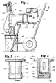
- Figure 1 is a side elevation view of portable spray painting equipment in which the present invention is useful.
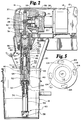
- Figure 2 is a partial section view of a portion of Figure 1, illustrating the present invention.
- Figure 3 is a side view of a quick-change mounting flange useful in the practice of the present invention.
- Figure 4 is a section view taken along line 4-4 of Figure 3.
- Figure 5 is an end view of the flange of Figure 3.
- Figure 6 is a partially exploded section view of a portion of Figure 2.
- Figure 7 is a section view of the fluid section assembly of the present invention utilizing lip type seals.
- Figure 8 is a partially cut away side view of a lip type seal useful in the embodiment shown in Figure 7.
- Figure 9 is a section view of the fluid section assembly of the present invention utilizing a pair of packing sets and an alternative inlet fitting assembly.
- Figure 10 is an exploded view of a packing set useful in the practice of the invention according to the embodiment shown in Figure 9.
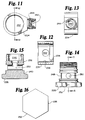
- Figure 11 is a top view of a inlet fitting yoke useful in the practice of the present invention in connection with the embodiment shown in Figure 9.
- Figure 12 is a section view taken along line 12-12 of Figure 11.
- Figure 13 is an end view of the yoke of Figure 11.
- Figure 14 is an inlet fitting post useful in the practice of the present invention according to the embodiment shown in Figure 9.
- Figure 15 is a section view taken along line 15-15 of Figure 14.
- Figure 16 is a bottom view of the post of Figure 14.
- Equipment 10 preferably has a prime mover such as an internal combustion engine 12 and clutch 14 driving a piston type paint pump 16 adapted to draw paint from a container or paint bucket 18.
- Equipment 10 is preferably mounted to and carried by a wheeled cart 20. It is to be understood that gasoline engine 12 and clutch 14 may be replaced by an electric motor or another suitable prime mover (not shown) to drive pump 16. Paint is supplied via an outlet fitting 138, and flexible hose 210 to a paint spray gun 212 having an on/off trigger 214.
- pump 16 preferably includes a gear reducer 22 connected to the output of clutch 14 (or to the electric motor, not shown).
- Reducer 22 has an output shaft 24 carried in a drive housing 26, preferably by anti-friction bearings 28, 30.
- Shaft 24 is preferably keyed to and drives an eccentric 28 which is rotatably coupled to a crank arm 30.
- Crank arm 30 is pivotably coupled to a slide 32 via a wrist pin 34.
- Slide 32 is preferably carried in a slide housing 36 secured to drive housing 26.
- a removeable drive housing cover 38 provides protection for the driving means 37 made up of the shaft 24, eccentric 28, and crank arm 30 and permits access to such parts upon removal of cover 38 from equipment 10.
- a fluid section assembly 40 is preferably mounted to the driving means 37 via a quick-change fluid section mounting flange 42.
- Fluid section assembly 40 includes a reciprocable piston 44 carried in a fluid section housing 46.
- Fluid section housing 46 is made up of an inlet portion 48 and an outlet portion 50.
- An inlet check valve 52 is carried by an inlet check valve housing 54 which is coupled to a suction tube 56 having a strainer 58 at its inlet end 60.
- Piston 44 preferably carries an outlet check valve 62 and has an internal passageway 64 coupled via a plurality of channels 66, 68 to an annular outlet chamber 70 in communication with an outlet port 72.
- suction tube 56 and inlet check valve housing 54 have communicating internal bores forming an inlet passageway 74.
- Figure 2 shows slide 32 both in an upper or retracted position 80 and also shows a partial section view of slide 32 coupled to piston 44 in a lower or extended position 82.
- slide 32 preferably has an internal axial bore 84 which receives an axial extension 86 of piston 44.
- Slide 32 also has a transverse or diametral bore 88. Bore 88 may be aligned with a similar transverse or diametral bore 90 in extension 86 when extension 86 is received in bore 84 of slide 32.
- Slide 32 and piston 44 are coupled together for bi-directional reciprocation by a connecting pin 92 when pin 92 is received in bores 88, 90.
- Pin 92 is retained in bores 88, 90 by a wire retaining clip received in a circumferencial groove 96 which intersects bore 88.
- Flange 42 has a first end 98 carrying a threaded axial bore 99.
- Flange 42 also has a second end 100 having a radially outwardly directed lip 102 having a plurality of keyhole-shaped axially oriented apertures 104 which extend through lip 102.
- Flange 42 further has an elongated generally cylindrical wall section 106 between first and second ends 98, 100. Wall section 106 has diametrically opposed, radially-oriented apertures 108, 110 therethrough.
- Flange 42 further has an interiorly directed lip 112 having a bore 114 therethrough.
- the fluid section assembly 40 may be removed from the driving means 37 by moving clip 94 out from diametral interference with diametral bores 88, 90 such that pin 92 may be removed through aperture 108 as is shown in Figure 6.
- Clip 94 may be moved along slide 32 as is shown at position 94a, or it may be completely removed, as indicated at 94b.
- each of the plurality of threaded fasteners 116 is loosened; flange 42 is rotated with respect to slide housing 36 such that the enlarged portions 118 (See Figure 5) of bores or apertures 104 are aligned with the enlarged heads 120 of fasteners 116.
- Fluid section assembly 40 is then axially displaced away from the driving means 37 and can be serviced or repaired with only one loose part, pin 92, separate from what are now two subassemblies of equipment 10.
- Flange 42 may now be removed by unthreading it from the remainder of fluid section assembly 40.
- suction tube 56 may be separated from the other end of fluid section assembly 40 by unscrewing a cap 55 from housing 54.
- Figure 7 shows a first embodiment of the fluid section assembly 40 utilizing a "U" cup type or lip type seals which have been found to provide longer life with latex type paints.
- a straight-line fluid section assembly 40 to accommodate an in-line suction tube 56 as indicated in Figures 1 and 2 and also it has been found desirable to provide for a swivel type inlet fitting 222 as shown in Figure 9 to provide for drawing paint from containers substantially larger than container 18.
- a flexible suction tube (not shown) is preferably secured to threads 244 on a rotating yoke or collar 224, with the other end of the flexible suction tube (not shown) leading to, for example, a 55 gallon drum or other container (not shown) of paint or other material to be pumped by equipment 10.
- fluid section assembly 40 includes piston 44 and an upper cylinder or outlet portion 50 of fluid section housing 46.
- Housing 46 also has a lower cylinder or inlet portion 48.
- Fluid section housing 46 thus is bifurcated or split in two parts and surrounds piston 44 and further has a first cylindrical annular recess 132 between housing 46 and piston 44 defined by inlet and outlet portions 48, 50.
- Upper cylinder 50 and lower cylinder 48 are preferably detachably secured together by interengaging threads 134.
- FIG. 7 there is a second cylindrical recess 136 between upper cylinder 128 and piston 44.
- Upper or second cylindrical recess 136 is preferably enclosed, in part, by inwardly directed lip 112 on flange 42.
- outlet portion 50 of fluid section housing 46 preferably has an outlet fitting 138 in outlet port 72 and is sealed by a copper gasket or seal in the form of a washer 140.
- Inlet check valve housing 54 carries an inlet check valve seat 142 and an inlet ball guide or cage 144 retained by an inlet sleeve 146.
- An O-ring 148 preferably seals housing 54 to housing section 48.
- a ball 150 acts as a check valve element for inlet check valve 52.
- a retainer nut 152 is preferably secured to piston 44 via threads 154. Nut 152 supports the outlet check valve seat 156, the outlet ball guide 158 and outlet check valve ball or element 160.
- inlet check valve 52 is open and the outlet check valve 62 is closed during upward movement of piston 44, and that the inlet check valve 52 is closed and the outlet check valve 62 is open during downward movement of piston 44, thus pumping paint from inlet passageway 74 to outlet port 72 during both upward and downward strokes of piston 44.
- paint at outlet 72 is at substantially higher pressure than paint at inlet 74, it is necessary that there be effective sealing between piston 44 and the housing 46 made up of inlet portion 48 and outlet portion 50. It is also necessary that piston 44 be sealed against outlet portion 50 in the area where piston 44 exits housing 46.
- First and second recesses 132, 136 provide respective annular spaces for such sealing means.
- a lip seal 162 such as that shown in Figure 8 and as available from the A.W. Chesterton Co., Stoneham, MA 02180 as a type 10000 series monoseal may be utilized as the sealing means.
- Lip seal 162 is preferably held in place by a seal carrier 164.
- Carrier 164 may have a wear ring 166 of teflon or other suitable material. Alternatively, wear ring 166 may be omitted.
- Seal carrier 164 is preferably sealed to housing 46 portions 48, 50 by O-rings 168, 170. In the first recess 132, it has been found preferable to use a second lip seal 174 identical to the first lip seal 162.
- a similar seal carrier 176 having a wear ring 182 and additional lip seal 178 may be utilized at the second recess 136.
- a conventional wiper 180 may be used to exclude external contaminants from the interior of assembly 40. Alternatively, wiper 180 may be eliminated for cost savings, as may wear ring 182 in carrier 176.
- a pair of blind bores 184, 186 are formed in inlet and outlet portions 48, 50 respectively. Bores 184, 186 are each adapted to receive a single-toothed spanner wrench to disassemble fluid section assembly 40.
- each of the inlet and outlet portions 48, 50 of housing 46 may be equipped with wrench flats or hexagonal or other open-end wrench/engaging surfaces as are conventionally known to separate two parts threaded together.
- the sealing means are provided by a packing set 187 made up of alternating leather and elastomer V-rings.
- the elastomer V-rings are preferably ultra high molecular weight polyethylene type rings.
- the leather V-ring 188 and the elastomer V-rings 190 are preferably compressed between a support ring 192 and a pressure ring 194.
- Support ring 192 and pressure ring 194 are preferably formed of delrin, as available from E.I. DuPont de Nemours Co.
- support ring 192 may be made of reinforced delrin or steel. Compression is applied to packing set 187 by a wave washer spring 196.
- the second packing set 202 preferably includes a similar stack of alternating leather and elastomer V-rings 204, 206, which are preferably retained between a second support ring 208 and second pressure ring 216 and compressed by a second wave washer 218.
- Figure 9 shows an alternative inlet fitting 222 which provides for both a right angle entry and a degree of freedom to permit the inlet port 220 to swivel or rotate around fluid section assembly 40'. It is further to be understood that pivoting inlet fitting 222 can be utilized in place of the inline inlet fitting 54 with the lip seal fluid section assembly 40 of Figure 7.
- Figure 9 shows wrench flat 254 on outlet portion 50 of housing 46 and flats 256, 258 on inlet portion 48, replacing bores 184, 186.
- pivoting fluid inlet fitting 222 preferably has a yoke 224 (shown in Figures 11, 12 and 13) and a post 226 (shown in Figures 14, 15 and 16).
- Yoke or cover 224 is received on post 226 and the combination is then threaded into inlet portion 48 and sealed against leakage by O-ring 148.
- Yoke 224 is sealed against leakage by O-rings 228, 230 which, at the same time permit yoke 224 to rotate on post 226.
- Yoke 224 preferably has a stepped bore 232 having a first inner diametral surface 234 having a clearance fit with a first diametral land 236 on post 226. Bore 232 also has a second inner diametral surface 238 sized to mate in a clearance fit with a second diametral land 240 on post 226. It is also to be understood that bore 232 is in communication with a transverse bore 242 in yoke 224, and that yoke 224 preferably has external threads 244 for coupling to a flexible syphon or suction inlet hose (not shown).
- Post 226 preferably has an internal configuration of a stepped bore 246, preferably identical to the corresponding internal configuration of inlet check valve housing 54. This internal configuration 246 supports the check valve seat 142, the inlet valve guide 144, and the inlet sleeve 146. Post 226 has a reduced diameter portion 248 having a through bore 250 in communication with stepped bore 246. Post 226 preferably has a hexagonal shaped end portion 252 to aid in attaching post 226 to inlet housing portion 48.
Landscapes
- Engineering & Computer Science (AREA)
- Mechanical Engineering (AREA)
- General Engineering & Computer Science (AREA)
- Details Of Reciprocating Pumps (AREA)
- Reciprocating Pumps (AREA)
- Nozzles (AREA)
- Coating Apparatus (AREA)
Abstract
Description
- This invention relates to the field of piston type fluid pumping devices used for high-pressure airless spraying. In the past, fluid sections for such pumping devices oftentimes required special tools for disassembly and were held together with tie bolts which, when removed, permitted all component parts to become loose items. This resulted in difficulties in servicing component parts of the fluid section in the field. In addition, prior art designs required that the fluid section use a single type of seal, typically a V-ring packing set, and thus limited adaptability of such prior art fluid sections to various service conditions. Furthermore, prior art designs had the packing set located in an annular recess which was relatively inaccessible by being axially remote within the pump even when the housing was disassembled. Such designs typically required special, not widely available tools to remove the packing set.
- The present invention overcomes deficiencies of the prior art by providing for a quick-change fluid section which allows for disassembly of only the component in the fluid section requiring servicing, and does so without the need for special tools, and furthermore permits the same fluid section to utilize either a V-ring type packing set or a "U" cup or lip type seal, depending upon service and life requirements. The present design makes the packing set or seal immediately available upon disassembly of the two portions of the fluid section housing.
- Figure 1 is a side elevation view of portable spray painting equipment in which the present invention is useful.
- Figure 2 is a partial section view of a portion of Figure 1, illustrating the present invention.
- Figure 3 is a side view of a quick-change mounting flange useful in the practice of the present invention.
- Figure 4 is a section view taken along line 4-4 of Figure 3.
- Figure 5 is an end view of the flange of Figure 3.
- Figure 6 is a partially exploded section view of a portion of Figure 2.
- Figure 7 is a section view of the fluid section assembly of the present invention utilizing lip type seals.
- Figure 8 is a partially cut away side view of a lip type seal useful in the embodiment shown in Figure 7.
- Figure 9 is a section view of the fluid section assembly of the present invention utilizing a pair of packing sets and an alternative inlet fitting assembly.
- Figure 10 is an exploded view of a packing set useful in the practice of the invention according to the embodiment shown in Figure 9.
- Figure 11 is a top view of a inlet fitting yoke useful in the practice of the present invention in connection with the embodiment shown in Figure 9.
- Figure 12 is a section view taken along line 12-12 of Figure 11.
- Figure 13 is an end view of the yoke of Figure 11.
- Figure 14 is an inlet fitting post useful in the practice of the present invention according to the embodiment shown in Figure 9.
- Figure 15 is a section view taken along line 15-15 of Figure 14.
- Figure 16 is a bottom view of the post of Figure 14.
- Referring now to Figure 1, portable
spray painting equipment 10 may be seen.Equipment 10 preferably has a prime mover such as aninternal combustion engine 12 andclutch 14 driving a pistontype paint pump 16 adapted to draw paint from a container orpaint bucket 18.Equipment 10 is preferably mounted to and carried by awheeled cart 20. It is to be understood thatgasoline engine 12 andclutch 14 may be replaced by an electric motor or another suitable prime mover (not shown) to drivepump 16. Paint is supplied via an outlet fitting 138, andflexible hose 210 to apaint spray gun 212 having an on/off trigger 214. - It is to be understood that once painting is completed, solvent is ordinarily flushed through
paint pump 16,hose 210 andgun 212 to clean paint from these items. Such flushing is not always adequate to completely clean paint fromequipment 10, and furthermore, it is sometimes necessary to get access to the interior, paint-contacting surfaces ofpump 16. Furthermore, because of the limitations of prior art systems, the use of a single type of seal resulted in less than ideal matching of the seal to the paint or other material to be pumped, and oftentimes required return of all or a portion ofpump 16 to a service center or to the factory for repair and replacement of parts. - Referring now to Figure 2,
pump 16 preferably includes agear reducer 22 connected to the output of clutch 14 (or to the electric motor, not shown).Reducer 22 has anoutput shaft 24 carried in adrive housing 26, preferably byanti-friction bearings crank arm 30.Crank arm 30 is pivotably coupled to aslide 32 via awrist pin 34.Slide 32 is preferably carried in aslide housing 36 secured to drivehousing 26. A removeabledrive housing cover 38 provides protection for the driving means 37 made up of theshaft 24, eccentric 28, andcrank arm 30 and permits access to such parts upon removal ofcover 38 fromequipment 10. - A
fluid section assembly 40 is preferably mounted to the driving means 37 via a quick-change fluidsection mounting flange 42.Fluid section assembly 40 includes areciprocable piston 44 carried in afluid section housing 46.Fluid section housing 46 is made up of aninlet portion 48 and anoutlet portion 50. Aninlet check valve 52 is carried by an inletcheck valve housing 54 which is coupled to asuction tube 56 having astrainer 58 at itsinlet end 60. Piston 44 preferably carries anoutlet check valve 62 and has aninternal passageway 64 coupled via a plurality ofchannels annular outlet chamber 70 in communication with anoutlet port 72. - It is to be understood that
suction tube 56 and inletcheck valve housing 54 have communicating internal bores forming aninlet passageway 74. - Figure 2 shows
slide 32 both in an upper or retractedposition 80 and also shows a partial section view ofslide 32 coupled topiston 44 in a lower or extendedposition 82. Referring now also to Figure 6,slide 32 preferably has an internalaxial bore 84 which receives anaxial extension 86 ofpiston 44.Slide 32 also has a transverse ordiametral bore 88. Bore 88 may be aligned with a similar transverse ordiametral bore 90 inextension 86 whenextension 86 is received inbore 84 ofslide 32.Slide 32 andpiston 44 are coupled together for bi-directional reciprocation by a connectingpin 92 whenpin 92 is received inbores Pin 92 is retained inbores circumferencial groove 96 which intersects bore 88. - Referring now more particularly to Figures 3-5, certain details of the
mounting flange 42 may be seen.Flange 42 has afirst end 98 carrying a threadedaxial bore 99.Flange 42 also has asecond end 100 having a radially outwardly directedlip 102 having a plurality of keyhole-shaped axiallyoriented apertures 104 which extend throughlip 102.Flange 42 further has an elongated generallycylindrical wall section 106 between first andsecond ends Wall section 106 has diametrically opposed, radially-oriented apertures Flange 42 further has an interiorly directedlip 112 having abore 114 therethrough. - Referring now more particularly again to Figures 2 and 6, the
fluid section assembly 40 may be removed from the driving means 37 by movingclip 94 out from diametral interference withdiametral bores pin 92 may be removed throughaperture 108 as is shown in Figure 6.Clip 94 may be moved alongslide 32 as is shown atposition 94a, or it may be completely removed, as indicated at 94b. Next, each of the plurality of threadedfasteners 116 is loosened;flange 42 is rotated with respect toslide housing 36 such that the enlarged portions 118 (See Figure 5) of bores orapertures 104 are aligned with the enlargedheads 120 offasteners 116.Fluid section assembly 40 is then axially displaced away from the driving means 37 and can be serviced or repaired with only one loose part,pin 92, separate from what are now two subassemblies ofequipment 10.Flange 42 may now be removed by unthreading it from the remainder offluid section assembly 40. In addition,suction tube 56 may be separated from the other end offluid section assembly 40 by unscrewing acap 55 fromhousing 54. - The
fluid section assembly 40 will then appear as shown in Figure 7. Figure 7 shows a first embodiment of thefluid section assembly 40 utilizing a "U" cup type or lip type seals which have been found to provide longer life with latex type paints. - Because such lip seals are more costly than V-ring packings, it has been found desirable to also permit the
fluid section assembly 40 to use V-ring packings as shown in Figure 9. It is important to note that thefluid section assembly 40 of the present invention may be converted between packing sets and lip type seals, and that such conversion may be accomplished in the field by a paint equipment operator, for example during overnight cleaning or daily maintenance ofequipment 10. Furthermore, by providing for the simple and easy removal offluid section assembly 40 from the driving means 37 painting equipment operators may find it desirable to have one or more sparefluid section assemblies 40 available in the event of a malfunction in thefluid section assembly 40 or to rapidly convert theequipment 10 from latex paint to oil-based paint or lacquer with which the packing type seals are preferred. To replace the seals it is only necessary to remove the fluid section assembly from the driving means, and then unscrew a mounting flange and two housing portions from each other to gain direct and immediate access to the seals. - It has also been found to be useful to have an option to provide a straight-line
fluid section assembly 40 to accommodate an in-line suction tube 56 as indicated in Figures 1 and 2 and also it has been found desirable to provide for a swivel type inlet fitting 222 as shown in Figure 9 to provide for drawing paint from containers substantially larger thancontainer 18. In such a case, a flexible suction tube (not shown) is preferably secured tothreads 244 on a rotating yoke orcollar 224, with the other end of the flexible suction tube (not shown) leading to, for example, a 55 gallon drum or other container (not shown) of paint or other material to be pumped byequipment 10. - Returning now to Figure 7,
fluid section assembly 40 includespiston 44 and an upper cylinder oroutlet portion 50 offluid section housing 46.Housing 46 also has a lower cylinder orinlet portion 48.Fluid section housing 46 thus is bifurcated or split in two parts and surroundspiston 44 and further has a first cylindricalannular recess 132 betweenhousing 46 andpiston 44 defined by inlet andoutlet portions Upper cylinder 50 andlower cylinder 48 are preferably detachably secured together byinterengaging threads 134. - As may be seen most clearly in Figure 7, there is a second
cylindrical recess 136 betweenupper cylinder 128 andpiston 44. Upper or secondcylindrical recess 136 is preferably enclosed, in part, by inwardly directedlip 112 onflange 42. - Referring now again to Figure 7,
outlet portion 50 offluid section housing 46 preferably has an outlet fitting 138 inoutlet port 72 and is sealed by a copper gasket or seal in the form of awasher 140. Inletcheck valve housing 54 carries an inletcheck valve seat 142 and an inlet ball guide orcage 144 retained by aninlet sleeve 146. An O-ring 148 preferably sealshousing 54 tohousing section 48. Aball 150 acts as a check valve element forinlet check valve 52. - Referring now to the
outlet check valve 62 inpiston 44, aretainer nut 152 is preferably secured topiston 44 viathreads 154.Nut 152 supports the outletcheck valve seat 156, theoutlet ball guide 158 and outlet check valve ball orelement 160. - It is to be understood that the
inlet check valve 52 is open and theoutlet check valve 62 is closed during upward movement ofpiston 44, and that theinlet check valve 52 is closed and theoutlet check valve 62 is open during downward movement ofpiston 44, thus pumping paint frominlet passageway 74 tooutlet port 72 during both upward and downward strokes ofpiston 44. Because paint atoutlet 72 is at substantially higher pressure than paint atinlet 74, it is necessary that there be effective sealing betweenpiston 44 and thehousing 46 made up ofinlet portion 48 andoutlet portion 50. It is also necessary thatpiston 44 be sealed againstoutlet portion 50 in the area wherepiston 44 exitshousing 46. First andsecond recesses lip seal 162 such as that shown in Figure 8 and as available from the A.W. Chesterton Co., Stoneham, MA 02180 as a type 10000 series monoseal may be utilized as the sealing means.Lip seal 162 is preferably held in place by aseal carrier 164.Carrier 164 may have awear ring 166 of teflon or other suitable material. Alternatively, wearring 166 may be omitted.Seal carrier 164 is preferably sealed tohousing 46portions rings first recess 132, it has been found preferable to use asecond lip seal 174 identical to thefirst lip seal 162. - A
similar seal carrier 176 having awear ring 182 andadditional lip seal 178 may be utilized at thesecond recess 136. Aconventional wiper 180 may be used to exclude external contaminants from the interior ofassembly 40. Alternatively,wiper 180 may be eliminated for cost savings, as may wearring 182 incarrier 176. - Although it is desirable to minimize the special tools required for disassembly of
equipment 10, it may be desirable to restrict access to the interior offluid section assembly 40, for example to those having special training and replacement components, and to carry out such purposes, a pair ofblind bores outlet portions Bores fluid section assembly 40. Alternatively, if it is not desired to restrict access, each of the inlet andoutlet portions housing 46 may be equipped with wrench flats or hexagonal or other open-end wrench/engaging surfaces as are conventionally known to separate two parts threaded together. - Referring now more particularly to Figure 9, an alternative embodiment of fluid section assembly 40' may be seen. In this embodiment, the sealing means are provided by a
packing set 187 made up of alternating leather and elastomer V-rings. The elastomer V-rings are preferably ultra high molecular weight polyethylene type rings. The leather V-ring 188 and the elastomer V-rings 190 are preferably compressed between asupport ring 192 and apressure ring 194.Support ring 192 andpressure ring 194 are preferably formed of delrin, as available from E.I. DuPont de Nemours Co. Alternatively,support ring 192 may be made of reinforced delrin or steel. Compression is applied to packing set 187 by awave washer spring 196. - In
second recess 136, it has been found preferable to utilize a packing sleeve 198 sealed by an O-ring 200. The second packing set 202 preferably includes a similar stack of alternating leather and elastomer V-rings second support ring 208 andsecond pressure ring 216 and compressed by asecond wave washer 218. - It is to be understood that the embodiment of Figure 9 can be utilized with the inlet
check valve housing 54 shown in Figure 7. Figure 9 shows an alternative inlet fitting 222 which provides for both a right angle entry and a degree of freedom to permit theinlet port 220 to swivel or rotate around fluid section assembly 40'. It is further to be understood that pivoting inlet fitting 222 can be utilized in place of the inline inlet fitting 54 with the lip sealfluid section assembly 40 of Figure 7. In addition, Figure 9 shows wrench flat 254 onoutlet portion 50 ofhousing 46 andflats inlet portion 48, replacingbores - Refer now also to Figures 11-16, in addition to Figure 9, pivoting fluid inlet fitting 222 preferably has a yoke 224 (shown in Figures 11, 12 and 13) and a post 226 (shown in Figures 14, 15 and 16).
- Yoke or cover 224 is received on
post 226 and the combination is then threaded intoinlet portion 48 and sealed against leakage by O-ring 148.Yoke 224 is sealed against leakage by O-rings time permit yoke 224 to rotate onpost 226. -
Yoke 224 preferably has a steppedbore 232 having a first innerdiametral surface 234 having a clearance fit with a firstdiametral land 236 onpost 226. Bore 232 also has a second innerdiametral surface 238 sized to mate in a clearance fit with a seconddiametral land 240 onpost 226. It is also to be understood thatbore 232 is in communication with atransverse bore 242 inyoke 224, and thatyoke 224 preferably hasexternal threads 244 for coupling to a flexible syphon or suction inlet hose (not shown). -
Post 226 preferably has an internal configuration of a steppedbore 246, preferably identical to the corresponding internal configuration of inletcheck valve housing 54. Thisinternal configuration 246 supports thecheck valve seat 142, theinlet valve guide 144, and theinlet sleeve 146.Post 226 has a reduceddiameter portion 248 having a throughbore 250 in communication with steppedbore 246.Post 226 preferably has a hexagonal shapedend portion 252 to aid in attachingpost 226 toinlet housing portion 48. - The invention is not to be taken as limited to all of the details thereof as modifications and variations thereof may be made without departing from the scope of the invention as claimed.
Claims (12)
- A fluid section coupling and mounting apparatus in a piston pump of the type having driving means carried in a drive housing (26) and coupled to a double acting piston (44) axially reciprocable in a fluid section housing (46), comprising:(a) a fluid section mounting flange (42) havingi) a first end (98) carrying a threaded axial bore (99) for engagement with a threaded end of the fluid section housing (46),ii) a second end (100) having a radially outwardly directed lip (102) having a plurality of key-hole-shaped axially-oriented apertures (104) therethrough, andiii) an elongated generally cylindrical wall section (106) between said first and second ends (98, 100) having diametrically opposed radially-oriented apertures (108) therethrough;b) a reciprocable coupling means for connecting the driving means to the piston (44) to reciprocate the piston with respect to the housing, the coupling means comprising:i) an axially oriented cylindrical section (32) of the driving means having both axial and diametral bores (84, 88) therein,ii) an axially projecting extension (86) at a first end of the piston (44) and having a diametral bore (90) therethrough,iii) a connecting pin (92) simultaneously transversely received in the diametral bores (88, 90) of the cylindrical section (32) of the driving means and the piston extension (86) such that when the piston extension is received in the axial bore (84) of the cylindrical section coupling the driving means to the piston for bidirectional reciprocation, andiv) pin retaining means (94b) for retaining the connecting pin (92) in the diametral bores (88, 90).
- The apparatus of claim 1 wherein the cylindrical section (32) has a circumferential groove (96) intersecting the diametral bore (88) of the cylindrical section and the pin retaining means comprises a circumferential wire clip (94b) received in the groove such that the pin (92) is retained in simultaneous engagement with the cylindrical section (32) and the piston extension (86).
- The apparatus of claim 2 wherein the wire clip (94b) and pin (92) are each accessible through one of the diametrically-opposed apertures (108) in the flange wall section (106) such that the clip is axially displaceable away from intersecting the diametral bore (88) of the cylindrical section and the pin (92) is thereafter transversely displaceable to decouple the cylindrical section and the piston extension.
- The apparatus of claim 1 or 2 wherein the flange (42) is selectively securable to a slide housing (36) by a plurality of threaded fasteners (116) threadably received in the pump frame and projecting through the keyhole-shaped apertures (104) in the flange lip (102).
- The apparatus of any of claims 1 to 4 wherein the fluid section housing (46) has an open-ended annular recess (136) at the threaded end thereof and the flange (42) further has an inwardly directed lip (112) adjacent the threaded axial bore (99) in the first end of the flange defining an end wall for the open-ended annular recess in the fluid section housing (46) and disengagement of the flange (42) and fluid section housing provides immediate and direct access to the open-ended annular recess (136).
- The apparatus of claim 5 further comprising end sealing means in the open-ended annular recess (136) for sealing the piston (44) to the fluid section housing (46).
- The apparatus of claim 6 wherein the end sealing means comprises an end packing set (202) having a plurality of alternating leather and elastomer V-ring packings (204, 206).
- The apparatus of claim 7 wherein the elastomer V-rings (204) of the end packing set are formed of ultra-high molecular weight polyethylene.
- The apparatus of claim 8 wherein the plurality of end V-ring packing (202) have an elastomer element (216) adjacent to a high-pressure end of the end packing set.
- The apparatus of claim 6 wherein the end sealing means comprises an elastomer lip end seal (178) and a metal end seal carrier (176).
- The apparatus of claim 10 wherein the end sealing means further comprises an elastomer wiper (180) carried by the metal end seal carrier.
- The apparatus of claim 11 wherein the metal end seal carrier has a wear ring (182) formed of tetrafluorethylene in contact with the piston.
Priority Applications (1)
| Application Number | Priority Date | Filing Date | Title |
|---|---|---|---|
| EP96118792A EP0770778A3 (en) | 1991-07-30 | 1992-07-07 | Quick-change fluid section for piston-type paint pumps |
Applications Claiming Priority (3)
| Application Number | Priority Date | Filing Date | Title |
|---|---|---|---|
| US07/735,794 US5228842A (en) | 1991-07-30 | 1991-07-30 | Quick-change fluid section for piston-type paint pumps |
| US735794 | 1991-07-30 | ||
| PCT/US1992/005665 WO1993003279A1 (en) | 1991-07-30 | 1992-07-07 | Quick-change fluid section for piston-type paint pumps |
Related Child Applications (2)
| Application Number | Title | Priority Date | Filing Date |
|---|---|---|---|
| EP96118792A Division EP0770778A3 (en) | 1991-07-30 | 1992-07-07 | Quick-change fluid section for piston-type paint pumps |
| EP96118792.9 Division-Into | 1996-11-22 |
Publications (3)
| Publication Number | Publication Date |
|---|---|
| EP0593645A1 EP0593645A1 (en) | 1994-04-27 |
| EP0593645A4 EP0593645A4 (en) | 1995-12-06 |
| EP0593645B1 true EP0593645B1 (en) | 1997-11-19 |
Family
ID=24957205
Family Applications (2)
| Application Number | Title | Priority Date | Filing Date |
|---|---|---|---|
| EP92915537A Expired - Lifetime EP0593645B1 (en) | 1991-07-30 | 1992-07-07 | Quick-change fluid section for piston-type paint pumps |
| EP96118792A Ceased EP0770778A3 (en) | 1991-07-30 | 1992-07-07 | Quick-change fluid section for piston-type paint pumps |
Family Applications After (1)
| Application Number | Title | Priority Date | Filing Date |
|---|---|---|---|
| EP96118792A Ceased EP0770778A3 (en) | 1991-07-30 | 1992-07-07 | Quick-change fluid section for piston-type paint pumps |
Country Status (9)
| Country | Link |
|---|---|
| US (2) | US5228842A (en) |
| EP (2) | EP0593645B1 (en) |
| JP (1) | JP2819503B2 (en) |
| KR (1) | KR0121999B1 (en) |
| AT (1) | ATE160425T1 (en) |
| CA (1) | CA2114321C (en) |
| DE (1) | DE69223245T2 (en) |
| ES (1) | ES2110004T3 (en) |
| WO (1) | WO1993003279A1 (en) |
Families Citing this family (71)
| Publication number | Priority date | Publication date | Assignee | Title |
|---|---|---|---|---|
| US5334001A (en) * | 1991-08-26 | 1994-08-02 | The Williams Pump Co. | Mounting arrangement for a positive displacement slurry pump |
| JPH09310725A (en) * | 1996-05-23 | 1997-12-02 | Exedy Corp | Modular clutch |
| US5655885A (en) * | 1995-03-31 | 1997-08-12 | Chung; Yang Woong | Reciprocating piston pump with modular fluid subassembly |
| CN1202223A (en) * | 1995-11-21 | 1998-12-16 | 瓦格纳喷涂技术有限公司 | Clamp ring for connecting pin |
| US5647737A (en) * | 1996-02-20 | 1997-07-15 | Ingersoll-Rand Company | Reciprocating pump with simplified seal replacement |
| US5671656A (en) * | 1996-02-20 | 1997-09-30 | Wagner Spray Tech Corporation | Paint pump fluid section |
| US5740718A (en) * | 1996-10-17 | 1998-04-21 | Binks Manufacturing Company | Modular piston rod assembly with integrated high-wear components |
| JP3821173B2 (en) * | 1996-12-19 | 2006-09-13 | 信越化学工業株式会社 | Epoxy resin composition |
| US6141995A (en) * | 1997-12-23 | 2000-11-07 | Maytag Corporation | Method and apparatus for mounting a pump to a washing machine |
| US6183225B1 (en) * | 1998-01-02 | 2001-02-06 | Graco Minnesota Inc. | Angled flow ports for reciprocating piston pump |
| US6212999B1 (en) * | 1998-01-02 | 2001-04-10 | Graco Minnesota Inc. | Automatic throat packing torque clip |
| US6212998B1 (en) * | 1998-01-02 | 2001-04-10 | Graco Minnesota Inc. | Packings on pump rod |
| EP1208287B1 (en) * | 1999-08-31 | 2006-07-26 | Graco Minnesota Inc. | Airless spray pump |
| US6419456B1 (en) | 1999-10-22 | 2002-07-16 | Wagner Spray Tech Corporation | Switch for controlling the motor of a piston pump |
| US6435846B1 (en) | 1999-10-22 | 2002-08-20 | Wagner Spray Tech Corporation | Piston pump having housing with a pump housing and a pump assembly drive housing formed therein |
| US6558141B2 (en) * | 2001-04-12 | 2003-05-06 | Ingersoll-Rand Company | Packing assembly and reciprocating plunger pump incorporating same |
| JP2003148598A (en) * | 2001-11-08 | 2003-05-21 | Honda Motor Co Ltd | Oil passage structure in the rotating shaft |
| DE10235140B4 (en) * | 2002-08-01 | 2005-02-17 | J. Wagner Gmbh | piston pump |
| US7444923B2 (en) * | 2002-08-12 | 2008-11-04 | Graco Minnesota Inc. | Synthetic leather packings for reciprocating piston pump |
| US7070017B2 (en) * | 2002-10-11 | 2006-07-04 | Hitachi Construction Machinery Co., Ltd | Rotating apparatus for construction machine |
| CN1918363A (en) * | 2004-01-20 | 2007-02-21 | 伊利诺斯器械工程公司 | material pump |
| USD516583S1 (en) | 2004-10-28 | 2006-03-07 | Illinois Tool Works Inc. | Pump |
| US7296981B2 (en) * | 2005-02-18 | 2007-11-20 | Illinois Tool Works Inc. | Pump having independently releasable ends |
| US7828527B2 (en) * | 2005-09-13 | 2010-11-09 | Illinois Tool Works Inc. | Paint circulating system and method |
| GB0518637D0 (en) * | 2005-09-13 | 2005-10-19 | Itw Ltd | Back pressure regulator |
| US7926740B2 (en) * | 2007-04-04 | 2011-04-19 | Black & Decker Inc. | Pressure washer system and operating method |
| US20080315552A1 (en) * | 2007-06-19 | 2008-12-25 | Mei-Yen Hsu | Dual-function bicycle seat post assembly |
| GB0715982D0 (en) * | 2007-08-15 | 2007-09-26 | Itw Ltd | Check valve |
| US20090179169A1 (en) * | 2008-01-11 | 2009-07-16 | Fleming Leslie E | Seal assembly for use with valves having a two-piece cage |
| US8986253B2 (en) | 2008-01-25 | 2015-03-24 | Tandem Diabetes Care, Inc. | Two chamber pumps and related methods |
| US20100008804A1 (en) * | 2008-04-18 | 2010-01-14 | Graco, Inc. | Pump having improved and adjustable packing |
| USD605664S1 (en) | 2008-08-07 | 2009-12-08 | Illinois Tool Works Inc. | Pump |
| US8408421B2 (en) | 2008-09-16 | 2013-04-02 | Tandem Diabetes Care, Inc. | Flow regulating stopcocks and related methods |
| CA2737461A1 (en) | 2008-09-19 | 2010-03-25 | Tandem Diabetes Care, Inc. | Solute concentration measurement device and related methods |
| US20100072300A1 (en) * | 2008-09-24 | 2010-03-25 | Miller William S | Paint sprayer |
| US8225968B2 (en) * | 2009-05-12 | 2012-07-24 | Illinois Tool Works Inc. | Seal system for gear pumps |
| EP2724739B1 (en) | 2009-07-30 | 2015-07-01 | Tandem Diabetes Care, Inc. | Portable infusion pump system |
| US20110079960A1 (en) * | 2009-10-07 | 2011-04-07 | Borden B Michael | Multi-Piece Pressure Operated Rings for a Downhole Pump Plunger |
| IT1403119B1 (en) * | 2010-12-16 | 2013-10-04 | Interpump Engineering Srl | PISTON PUMP GUIDE |
| US9180242B2 (en) | 2012-05-17 | 2015-11-10 | Tandem Diabetes Care, Inc. | Methods and devices for multiple fluid transfer |
| US9173998B2 (en) | 2013-03-14 | 2015-11-03 | Tandem Diabetes Care, Inc. | System and method for detecting occlusions in an infusion pump |
| DE102014006759A1 (en) * | 2014-05-08 | 2015-11-12 | Dürr Systems GmbH | Exhaust air duct for a coating agent pump |
| US10253771B2 (en) * | 2014-09-10 | 2019-04-09 | Tritech Industries, Inc. | High pressure paint pump |
| US10941762B2 (en) | 2015-01-30 | 2021-03-09 | Wagner Spray Tech Corporation | Piston limit sensing and software control for fluid application |
| US20160222995A1 (en) * | 2015-01-30 | 2016-08-04 | Wagner Spray Tech Corporation | Piston limit sensing for fluid application |
| EP3338011B1 (en) * | 2015-08-21 | 2020-02-26 | Graco Minnesota Inc. | Packing stacks for piston pumps |
| CN108350874B (en) * | 2015-11-11 | 2021-08-27 | 固瑞克明尼苏达有限公司 | Ball cage with directional flow path for ball pump |
| AU2016277741B2 (en) | 2015-12-30 | 2022-06-02 | Graco Minnesota Inc. | Rotating piston for pumps |
| CN106955807B (en) | 2016-01-12 | 2019-07-05 | 固瑞克明尼苏达有限公司 | Integrated pump guard and control interlock |
| CN106958525B (en) * | 2016-01-12 | 2020-09-29 | 固瑞克明尼苏达有限公司 | Piston rod with cap recess |
| ITUB20160032A1 (en) * | 2016-01-26 | 2017-07-26 | Inkmaker S R L | ALTERNATIVE PUMP, IN PARTICULAR TYPE OF VACUUM, FOR THE SUCKING AND DISTRIBUTION OF A FLUID, IN PARTICULAR A COLORED FLUID |
| US10815990B2 (en) * | 2016-04-11 | 2020-10-27 | Graco Minnesota Inc. | Paint sprayer pump cartridge |
| US11440038B2 (en) * | 2019-01-25 | 2022-09-13 | Graco Minnesota Inc. | Material sprayer |
| US11572876B2 (en) | 2017-08-30 | 2023-02-07 | Graco Minnesota Inc. | Pump piston |
| US12135048B2 (en) | 2017-09-07 | 2024-11-05 | Wagner Spray Tech Corporation | Piston limit sensing for fluid application |
| US10801493B2 (en) | 2017-12-14 | 2020-10-13 | William E. Howseman, Jr. | Positive displacement reciprocating pump assembly for dispensing predeterminedly precise amounts of fluid during both the up and down strokes of the pump piston |
| US11458605B2 (en) * | 2018-03-28 | 2022-10-04 | Graco Minnesota Inc. | Packing insertion tool for paint and other fluid pumps |
| US10989306B2 (en) | 2018-03-28 | 2021-04-27 | Graco Minnesota Inc. | Packing stack carrier for paint and other fluid pumps |
| EP3887682B1 (en) | 2018-11-27 | 2024-06-12 | Graco Minnesota Inc. | Rotating piston rod for spray fluid pump |
| FR3091825B1 (en) * | 2019-01-23 | 2022-08-12 | Exel Ind | Pump for liquid product comprising a sealing device and spraying installation comprising such a pump |
| US11406995B2 (en) | 2019-01-25 | 2022-08-09 | Graco Minnesota Inc. | Material spray gun |
| DE102019106681B4 (en) * | 2019-03-15 | 2023-02-23 | Perma-Tec Gmbh & Co. Kg | lubricator |
| FR3096095B1 (en) * | 2019-05-16 | 2021-12-31 | Exel Ind | Pump for a coating product application system and use of such a pump |
| US11109543B2 (en) * | 2019-12-05 | 2021-09-07 | Shun-Tsung Lu | Soil irrigation and restoration method and system of the same |
| CN212429124U (en) * | 2020-02-21 | 2021-01-29 | 广州市安途电器有限公司 | Inflating pump |
| AU2021280300A1 (en) | 2020-05-29 | 2022-12-08 | Graco Minnesota Inc. | Pump and drive assembly |
| AU2021282335A1 (en) * | 2020-05-29 | 2022-12-08 | Graco Minnesota Inc. | Transfer pump |
| US11725641B2 (en) | 2020-10-29 | 2023-08-15 | William E. Howseman, Jr. | Double-acting reciprocating pump assembly for use in conjunction with a melter |
| CN113082822A (en) * | 2021-04-23 | 2021-07-09 | 承德石油高等专科学校 | Filtering liquid-changing device |
| US20230034134A1 (en) * | 2021-07-28 | 2023-02-02 | Wagner Spray Tech Corporation | Screw driven piston pump |
| US12624686B2 (en) * | 2022-10-27 | 2026-05-12 | Alemite Llc | Battery-operated reciprocating pump for lubricants |
Family Cites Families (22)
| Publication number | Priority date | Publication date | Assignee | Title |
|---|---|---|---|---|
| US2188957A (en) * | 1936-03-11 | 1940-02-06 | Blackhawk Mfg Co | Packing |
| GB562820A (en) * | 1943-03-02 | 1944-07-18 | Joseph Coblentz Groff | Improvements in or relating to plunger pumps |
| US2587405A (en) * | 1947-01-15 | 1952-02-26 | Sealol Corp | Seal for relatively rotating members |
| US2644701A (en) * | 1948-11-10 | 1953-07-07 | Miller Motor Company | Piston rod seal |
| US3003797A (en) * | 1958-11-17 | 1961-10-10 | Gage Arthur Glover | Packing assembly |
| US2982590A (en) * | 1959-03-30 | 1961-05-02 | Clark Equipment Co | Cylinder construction |
| US3069178A (en) * | 1959-09-22 | 1962-12-18 | Rosen Sidney | Sealing arrangement for a pump |
| US3011808A (en) * | 1959-12-03 | 1961-12-05 | John W Mecom | Pump packing |
| US3330217A (en) * | 1965-07-20 | 1967-07-11 | Binks Mfg Co | Pump |
| US3351350A (en) * | 1966-06-22 | 1967-11-07 | Koppers Co Inc | High pressure rod seal |
| DE1653351B1 (en) * | 1966-10-01 | 1971-06-03 | Applied Power Ind Inc | Liquid piston pump |
| US3502029A (en) * | 1968-08-08 | 1970-03-24 | Grant Halladay | Pumps |
| US3827339A (en) * | 1969-03-21 | 1974-08-06 | Nordson Corp | Double acting hydraulic pump |
| US4009971A (en) * | 1974-06-07 | 1977-03-01 | Binks Manufacturing Company | Electric motor-driven, double-acting pump having pressure-responsive actuation |
| US4262915A (en) * | 1978-04-17 | 1981-04-21 | Commercial Shearing, Inc. | Low friction drag seals |
| WO1982003670A1 (en) * | 1980-11-21 | 1982-10-28 | Harold L Reinsma | Seal assembly having a plastic annular sealing member with an integral sealing lip |
| US4440404A (en) * | 1982-08-09 | 1984-04-03 | Halliburton Company | Packing arrangement |
| US4516752A (en) * | 1984-01-12 | 1985-05-14 | Joy Manufacturing Company | Mechanically preloaded packing assembly |
| US4661052A (en) * | 1984-11-19 | 1987-04-28 | Ruhle James L | Reciprocating down-hole sand pump |
| US4775303A (en) * | 1985-02-08 | 1988-10-04 | Miroslav Liska | Pump having adjustable packing |
| US4921407A (en) * | 1989-05-22 | 1990-05-01 | Mack Ponder | Production pump for high gravity or sand laden oil |
| US5094596A (en) * | 1990-06-01 | 1992-03-10 | Binks Manufacturing Company | High pressure piston pump for fluent materials |
-
1991
- 1991-07-30 US US07/735,794 patent/US5228842A/en not_active Expired - Fee Related
-
1992
- 1992-07-07 JP JP5503560A patent/JP2819503B2/en not_active Expired - Lifetime
- 1992-07-07 ES ES92915537T patent/ES2110004T3/en not_active Expired - Lifetime
- 1992-07-07 EP EP92915537A patent/EP0593645B1/en not_active Expired - Lifetime
- 1992-07-07 AT AT92915537T patent/ATE160425T1/en not_active IP Right Cessation
- 1992-07-07 DE DE69223245T patent/DE69223245T2/en not_active Expired - Fee Related
- 1992-07-07 CA CA002114321A patent/CA2114321C/en not_active Expired - Fee Related
- 1992-07-07 EP EP96118792A patent/EP0770778A3/en not_active Ceased
- 1992-07-07 WO PCT/US1992/005665 patent/WO1993003279A1/en not_active Ceased
- 1992-07-30 KR KR1019920013652A patent/KR0121999B1/en not_active Expired - Fee Related
-
1994
- 1994-09-16 US US08/307,390 patent/US5435697A/en not_active Expired - Lifetime
Also Published As
| Publication number | Publication date |
|---|---|
| JPH07500162A (en) | 1995-01-05 |
| US5228842A (en) | 1993-07-20 |
| CA2114321C (en) | 1997-01-21 |
| WO1993003279A1 (en) | 1993-02-18 |
| DE69223245T2 (en) | 1998-06-18 |
| JP2819503B2 (en) | 1998-10-30 |
| CA2114321A1 (en) | 1993-02-18 |
| KR0121999B1 (en) | 1997-11-12 |
| ES2110004T3 (en) | 1998-02-01 |
| ATE160425T1 (en) | 1997-12-15 |
| US5435697A (en) | 1995-07-25 |
| EP0770778A3 (en) | 1997-11-05 |
| DE69223245D1 (en) | 1998-01-02 |
| EP0593645A1 (en) | 1994-04-27 |
| KR930001989A (en) | 1993-02-22 |
| EP0770778A2 (en) | 1997-05-02 |
| EP0593645A4 (en) | 1995-12-06 |
Similar Documents
| Publication | Publication Date | Title |
|---|---|---|
| US5228842A (en) | Quick-change fluid section for piston-type paint pumps | |
| US12313061B2 (en) | Fluid dispensing system having a piston rod and wear sleeve | |
| CA1310228C (en) | Pump head for a high pressure pump | |
| US5415531A (en) | Piston pump for fluent materials | |
| US3931755A (en) | Pump | |
| US5740718A (en) | Modular piston rod assembly with integrated high-wear components | |
| US5671656A (en) | Paint pump fluid section | |
| US5398944A (en) | Sealing system for reciprocating rod | |
| CN109882372A (en) | A kind of reciprocating three-cylinder plunger pump of oil gas field | |
| US20040161351A1 (en) | High pressure fluid pump system having variable displacement through replaceable cartridges | |
| US10935023B2 (en) | Pump for liquid product comprising a sealing device and spraying installation comprising such a pump | |
| US5346037A (en) | Packing nut and rod guide for piston paint pumps | |
| US5655885A (en) | Reciprocating piston pump with modular fluid subassembly | |
| KR20230032107A (en) | r manufacturing the same | |
| US3248020A (en) | High pressure source for viscous liquids, especially those containing suspended abrasive particles | |
| US3817663A (en) | Reciprocating pump | |
| US6568925B2 (en) | Abrasive liquid pump apparatus and method |
Legal Events
| Date | Code | Title | Description |
|---|---|---|---|
| PUAI | Public reference made under article 153(3) epc to a published international application that has entered the european phase |
Free format text: ORIGINAL CODE: 0009012 |
|
| 17P | Request for examination filed |
Effective date: 19940128 |
|
| AK | Designated contracting states |
Kind code of ref document: A1 Designated state(s): AT BE CH DE DK ES FR GB IT LI NL SE |
|
| A4 | Supplementary search report drawn up and despatched |
Effective date: 19951020 |
|
| AK | Designated contracting states |
Kind code of ref document: A4 Designated state(s): AT BE CH DE DK ES FR GB IT LI NL SE |
|
| 17Q | First examination report despatched |
Effective date: 19960715 |
|
| GRAG | Despatch of communication of intention to grant |
Free format text: ORIGINAL CODE: EPIDOS AGRA |
|
| GRAH | Despatch of communication of intention to grant a patent |
Free format text: ORIGINAL CODE: EPIDOS IGRA |
|
| GRAH | Despatch of communication of intention to grant a patent |
Free format text: ORIGINAL CODE: EPIDOS IGRA |
|
| GRAA | (expected) grant |
Free format text: ORIGINAL CODE: 0009210 |
|
| AK | Designated contracting states |
Kind code of ref document: B1 Designated state(s): AT BE CH DE DK ES FR GB IT LI NL SE |
|
| DX | Miscellaneous (deleted) | ||
| PG25 | Lapsed in a contracting state [announced via postgrant information from national office to epo] |
Ref country code: NL Free format text: LAPSE BECAUSE OF FAILURE TO SUBMIT A TRANSLATION OF THE DESCRIPTION OR TO PAY THE FEE WITHIN THE PRESCRIBED TIME-LIMIT Effective date: 19971119 Ref country code: LI Free format text: LAPSE BECAUSE OF FAILURE TO SUBMIT A TRANSLATION OF THE DESCRIPTION OR TO PAY THE FEE WITHIN THE PRESCRIBED TIME-LIMIT Effective date: 19971119 Ref country code: DK Free format text: LAPSE BECAUSE OF NON-PAYMENT OF DUE FEES Effective date: 19971119 Ref country code: CH Free format text: LAPSE BECAUSE OF FAILURE TO SUBMIT A TRANSLATION OF THE DESCRIPTION OR TO PAY THE FEE WITHIN THE PRESCRIBED TIME-LIMIT Effective date: 19971119 Ref country code: BE Free format text: LAPSE BECAUSE OF FAILURE TO SUBMIT A TRANSLATION OF THE DESCRIPTION OR TO PAY THE FEE WITHIN THE PRESCRIBED TIME-LIMIT Effective date: 19971119 Ref country code: AT Free format text: LAPSE BECAUSE OF FAILURE TO SUBMIT A TRANSLATION OF THE DESCRIPTION OR TO PAY THE FEE WITHIN THE PRESCRIBED TIME-LIMIT Effective date: 19971119 |
|
| REF | Corresponds to: |
Ref document number: 160425 Country of ref document: AT Date of ref document: 19971215 Kind code of ref document: T |
|
| ITF | It: translation for a ep patent filed | ||
| REG | Reference to a national code |
Ref country code: CH Ref legal event code: EP |
|
| REF | Corresponds to: |
Ref document number: 69223245 Country of ref document: DE Date of ref document: 19980102 |
|
| ET | Fr: translation filed | ||
| REG | Reference to a national code |
Ref country code: ES Ref legal event code: FG2A Ref document number: 2110004 Country of ref document: ES Kind code of ref document: T3 |
|
| PG25 | Lapsed in a contracting state [announced via postgrant information from national office to epo] |
Ref country code: SE Free format text: LAPSE BECAUSE OF FAILURE TO SUBMIT A TRANSLATION OF THE DESCRIPTION OR TO PAY THE FEE WITHIN THE PRESCRIBED TIME-LIMIT Effective date: 19980219 |
|
| NLV1 | Nl: lapsed or annulled due to failure to fulfill the requirements of art. 29p and 29m of the patents act | ||
| REG | Reference to a national code |
Ref country code: CH Ref legal event code: PL |
|
| PLBE | No opposition filed within time limit |
Free format text: ORIGINAL CODE: 0009261 |
|
| STAA | Information on the status of an ep patent application or granted ep patent |
Free format text: STATUS: NO OPPOSITION FILED WITHIN TIME LIMIT |
|
| 26N | No opposition filed | ||
| PGFP | Annual fee paid to national office [announced via postgrant information from national office to epo] |
Ref country code: FR Payment date: 20000711 Year of fee payment: 9 |
|
| PGFP | Annual fee paid to national office [announced via postgrant information from national office to epo] |
Ref country code: GB Payment date: 20000713 Year of fee payment: 9 |
|
| PGFP | Annual fee paid to national office [announced via postgrant information from national office to epo] |
Ref country code: DE Payment date: 20000717 Year of fee payment: 9 |
|
| PGFP | Annual fee paid to national office [announced via postgrant information from national office to epo] |
Ref country code: ES Payment date: 20000830 Year of fee payment: 9 |
|
| PG25 | Lapsed in a contracting state [announced via postgrant information from national office to epo] |
Ref country code: GB Free format text: LAPSE BECAUSE OF NON-PAYMENT OF DUE FEES Effective date: 20010707 |
|
| PG25 | Lapsed in a contracting state [announced via postgrant information from national office to epo] |
Ref country code: ES Free format text: LAPSE BECAUSE OF NON-PAYMENT OF DUE FEES Effective date: 20010708 |
|
| GBPC | Gb: european patent ceased through non-payment of renewal fee |
Effective date: 20010707 |
|
| PG25 | Lapsed in a contracting state [announced via postgrant information from national office to epo] |
Ref country code: FR Free format text: LAPSE BECAUSE OF NON-PAYMENT OF DUE FEES Effective date: 20020329 |
|
| PG25 | Lapsed in a contracting state [announced via postgrant information from national office to epo] |
Ref country code: DE Free format text: LAPSE BECAUSE OF NON-PAYMENT OF DUE FEES Effective date: 20020501 |
|
| REG | Reference to a national code |
Ref country code: FR Ref legal event code: ST |
|
| REG | Reference to a national code |
Ref country code: ES Ref legal event code: FD2A Effective date: 20020810 |
|
| PG25 | Lapsed in a contracting state [announced via postgrant information from national office to epo] |
Ref country code: IT Free format text: LAPSE BECAUSE OF NON-PAYMENT OF DUE FEES;WARNING: LAPSES OF ITALIAN PATENTS WITH EFFECTIVE DATE BEFORE 2007 MAY HAVE OCCURRED AT ANY TIME BEFORE 2007. THE CORRECT EFFECTIVE DATE MAY BE DIFFERENT FROM THE ONE RECORDED. Effective date: 20050707 |