EP0592839A1 - Retention cage for the balls of rolling-contact bearings - Google Patents
Retention cage for the balls of rolling-contact bearings Download PDFInfo
- Publication number
- EP0592839A1 EP0592839A1 EP93114992A EP93114992A EP0592839A1 EP 0592839 A1 EP0592839 A1 EP 0592839A1 EP 93114992 A EP93114992 A EP 93114992A EP 93114992 A EP93114992 A EP 93114992A EP 0592839 A1 EP0592839 A1 EP 0592839A1
- Authority
- EP
- European Patent Office
- Prior art keywords
- balls
- cage
- couplers
- cavities
- base ring
- Prior art date
- Legal status (The legal status is an assumption and is not a legal conclusion. Google has not performed a legal analysis and makes no representation as to the accuracy of the status listed.)
- Granted
Links
Images
Classifications
-
- F—MECHANICAL ENGINEERING; LIGHTING; HEATING; WEAPONS; BLASTING
- F16—ENGINEERING ELEMENTS AND UNITS; GENERAL MEASURES FOR PRODUCING AND MAINTAINING EFFECTIVE FUNCTIONING OF MACHINES OR INSTALLATIONS; THERMAL INSULATION IN GENERAL
- F16C—SHAFTS; FLEXIBLE SHAFTS; ELEMENTS OR CRANKSHAFT MECHANISMS; ROTARY BODIES OTHER THAN GEARING ELEMENTS; BEARINGS
- F16C19/00—Bearings with rolling contact, for exclusively rotary movement
- F16C19/02—Bearings with rolling contact, for exclusively rotary movement with bearing balls essentially of the same size in one or more circular rows
- F16C19/14—Bearings with rolling contact, for exclusively rotary movement with bearing balls essentially of the same size in one or more circular rows for both radial and axial load
-
- F—MECHANICAL ENGINEERING; LIGHTING; HEATING; WEAPONS; BLASTING
- F16—ENGINEERING ELEMENTS AND UNITS; GENERAL MEASURES FOR PRODUCING AND MAINTAINING EFFECTIVE FUNCTIONING OF MACHINES OR INSTALLATIONS; THERMAL INSULATION IN GENERAL
- F16C—SHAFTS; FLEXIBLE SHAFTS; ELEMENTS OR CRANKSHAFT MECHANISMS; ROTARY BODIES OTHER THAN GEARING ELEMENTS; BEARINGS
- F16C33/00—Parts of bearings; Special methods for making bearings or parts thereof
- F16C33/30—Parts of ball or roller bearings
- F16C33/38—Ball cages
- F16C33/41—Ball cages comb-shaped
- F16C33/412—Massive or moulded comb cages, e.g. snap ball cages
- F16C33/414—Massive or moulded comb cages, e.g. snap ball cages formed as one-piece cages, i.e. monoblock comb cages
-
- F—MECHANICAL ENGINEERING; LIGHTING; HEATING; WEAPONS; BLASTING
- F16—ENGINEERING ELEMENTS AND UNITS; GENERAL MEASURES FOR PRODUCING AND MAINTAINING EFFECTIVE FUNCTIONING OF MACHINES OR INSTALLATIONS; THERMAL INSULATION IN GENERAL
- F16C—SHAFTS; FLEXIBLE SHAFTS; ELEMENTS OR CRANKSHAFT MECHANISMS; ROTARY BODIES OTHER THAN GEARING ELEMENTS; BEARINGS
- F16C33/00—Parts of bearings; Special methods for making bearings or parts thereof
- F16C33/30—Parts of ball or roller bearings
- F16C33/38—Ball cages
- F16C33/41—Ball cages comb-shaped
- F16C33/418—Details of individual pockets, e.g. shape or ball retaining means
Definitions
- This invention relates to a retention cage for the balls contained in rolling-contact bearings.
- An object of the invention is to provide a retention cage which enables the space between two adjacent balls to be reduced to a minimum in order to be able to increase the number of balls or to use larger diameter balls for the same ball bearing, so increasing the loading capacity of the bearing and hence its life.
- a further object of the invention is to provide a cage in which friction against the balls is reduced to a minimum.
- a further object of the invention is to provide a cage which allows improved lubricant grease circulation within the bearing.
- a retention cage for bearing balls of the type consisting of a circular base ring from which a crown of seats or cavities for receiving the bearing balls extends, characterised in that the cavities are defined by a crown of radial couplers arranged to retain the balls along a sheaf of lines of action which pass through the centre of each of the balls and are slightly inclined to the plane in which the balls roll.
- a cage according to the present invention is indicated overall by the reference numeral 10.
- the cage 10 consists of a circular base ring 11, on one side of which there is formed in one piece therewith a crown of equidistantly spaced radial couplers 12.
- the couplers 12 have a substantially C-shaped axial section and are shaped to define, within the spaces between two adjacent couplers, a plurality of spherical seats or cavities 13 arranged to receive corresponding rolling balls 14 (Figure 3 ) which are arranged as a ring between the bearing races (not shown for simplicity) and are maintained a constant distance apart by the cage 10.
- Each spherical cavity 13 is substantially defined by three concave surfaces joined together, namely two surfaces 15 and 16 provided respectively on the opposing faces of two adjacent couplers 12 and a third concave surface 17 joining the first two together and provided on the base ring 11.
- the couplers 12 are composed of two curved portions projecting from the ring 11, namely a longer portion 19 and a shorter portion 20, both having diverging ends 19a and 20a and cooperating with the adjacent couplers 12 to retain the balls 14.
- the portions 19 and 20 cover an arc extending through more than 180° in an axial plane.
- the configuration of the couplers 12 is such that the resultant of the actions and reactions transferred between each ball and the two adjacent couplers which retain it has a line of action r passing through the centre C of each ball, and substantially parallel or slightly inclined to the plane p in which the balls roll, this being perpendicular to the axis of rotation x of the bearing.
Landscapes
- Engineering & Computer Science (AREA)
- General Engineering & Computer Science (AREA)
- Mechanical Engineering (AREA)
- Rolling Contact Bearings (AREA)
Abstract
Description
- This invention relates to a retention cage for the balls contained in rolling-contact bearings.
- Various types of retention cage for ball bearings are known, in which the balls are separated from each other by radial walls carried by a base ring.
- An object of the invention is to provide a retention cage which enables the space between two adjacent balls to be reduced to a minimum in order to be able to increase the number of balls or to use larger diameter balls for the same ball bearing, so increasing the loading capacity of the bearing and hence its life.
- A further object of the invention is to provide a cage in which friction against the balls is reduced to a minimum.
- A further object of the invention is to provide a cage which allows improved lubricant grease circulation within the bearing.
- These and further objects and advantages which will be more apparent from the ensuing description are attained according to the present invention by a retention cage for bearing balls, of the type consisting of a circular base ring from which a crown of seats or cavities for receiving the bearing balls extends, characterised in that the cavities are defined by a crown of radial couplers arranged to retain the balls along a sheaf of lines of action which pass through the centre of each of the balls and are slightly inclined to the plane in which the balls roll.
- The structural and functional characteristics of a preferred but non-limiting embodiment of the cage according to the invention are described hereinafter with reference to the accompanying drawings, in which:
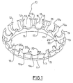
- Figure 1 is a perspective view of the cage according to the invention;
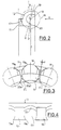
- Figure 2 is a cross-section through the cage of Figure 1, to an enlarged scale;
- Figure 3 is a partial front view of the cage in the direction of the arrow A of Figure 2; and
- Figure 4 is a partial view of the cage from above in the direction of the arrow B of Figure 2.
- With reference initially to Figure 1, a cage according to the present invention is indicated overall by the
reference numeral 10. - The
cage 10 consists of acircular base ring 11, on one side of which there is formed in one piece therewith a crown of equidistantly spacedradial couplers 12. - As shown in Figure 2, the
couplers 12 have a substantially C-shaped axial section and are shaped to define, within the spaces between two adjacent couplers, a plurality of spherical seats orcavities 13 arranged to receive corresponding rolling balls 14 (Figure 3 ) which are arranged as a ring between the bearing races (not shown for simplicity) and are maintained a constant distance apart by thecage 10. - Each
spherical cavity 13 is substantially defined by three concave surfaces joined together, namely twosurfaces adjacent couplers 12 and a thirdconcave surface 17 joining the first two together and provided on thebase ring 11. - The
couplers 12 are composed of two curved portions projecting from thering 11, namely alonger portion 19 and ashorter portion 20, both having divergingends adjacent couplers 12 to retain theballs 14. - As shown in Figure 2, to effectively retain the balls the
portions couplers 12 is such that the resultant of the actions and reactions transferred between each ball and the two adjacent couplers which retain it has a line of action r passing through the centre C of each ball, and substantially parallel or slightly inclined to the plane p in which the balls roll, this being perpendicular to the axis of rotation x of the bearing. - The seats or cavities defined in this manner all intercommunicate in a circumferential direction; this enables the distance d (Figure 3 ) between two adjacent balls to be reduced to a minimum without them mutually interfering. As will be apparent, compared with the known art the space teen up by the radial walls mentioned in the introduction to the present description is eliminated. Consequently, as the available space is greater, the number and/or diameter of the balls can be increased to give greater loading capacity to the bearing and hence a longer life.
- In addition, as the contact surfaces between the balls and the cage of the present invention are very small in area, the overall friction between the balls and cage is reduced.
- Moreover, as the ball seats communicate with each other in the central spherical region of the balls, there is a net improvement in the distribution of lubricant grease over all the balls contained in the bearing.
Claims (5)
- A retention cage for bearing balls, of the type consisting of a circular base ring (11) from which a crown of seats or cavities (13) for receiving the bearing balls (14) extends, characterised in that the cavities (13) are defined by a crown of radial couplers (12) arranged to retain the balls (14) along a sheaf of lines of action (r) which pass through the centre of each ball and are slightly inclined to the plane (p) in which the balls roll.
- A cage as claimed in claim 1, characterised in that the couplers (12) are substantially of C-shaped cross-section.
- A cage as claimed in claim 1, characterised in that the couplers 12 are composed of two curved portions (19, 20)) projecting from the base ring (11), namely a longer portion (19) and a shorter portion (20), both having their respective ends (19a, 20a) diverging in a circumferential direction.
- A cage as claimed in the preceding claims, characterised in that each spherical cavity (13) is substantially defined by three concave surfaces (15, 16, 17) joined together, of which two surfaces (15, 16) are provided respectively on the opposing faces of two adjacent couplers (12), and the third surface (17) joining the first two together is provided on the base ring (11).
- A cage as claimed in claims 1 and 2, characterised in that the cavities (13) communicate with each other in the central spherical region of the balls (14).
Applications Claiming Priority (2)
| Application Number | Priority Date | Filing Date | Title |
|---|---|---|---|
| ITTO920248U | 1992-10-15 | ||
| IT92TO000248U IT227660Y1 (en) | 1992-10-15 | 1992-10-15 | RETAINING CAGE FOR BALL BEARINGS. |
Publications (2)
| Publication Number | Publication Date |
|---|---|
| EP0592839A1 true EP0592839A1 (en) | 1994-04-20 |
| EP0592839B1 EP0592839B1 (en) | 1996-07-03 |
Family
ID=11410270
Family Applications (1)
| Application Number | Title | Priority Date | Filing Date |
|---|---|---|---|
| EP93114992A Expired - Lifetime EP0592839B1 (en) | 1992-10-15 | 1993-09-17 | Retention cage for the balls of rolling-contact bearings |
Country Status (3)
| Country | Link |
|---|---|
| EP (1) | EP0592839B1 (en) |
| DE (1) | DE69303451T2 (en) |
| IT (1) | IT227660Y1 (en) |
Cited By (7)
| Publication number | Priority date | Publication date | Assignee | Title |
|---|---|---|---|---|
| EP1070866A1 (en) * | 1999-07-23 | 2001-01-24 | Skf France | Bearing cage and bearing |
| WO2006027342A1 (en) | 2004-09-09 | 2006-03-16 | Aktiebolaget Skf | Ball bearing unit with an improved ball retaining cage |
| DE102004003106B4 (en) * | 2003-01-31 | 2006-05-11 | Skf Industrie S.P.A. | Cage for rolling element bearings |
| FR2878006A3 (en) * | 2005-05-26 | 2006-05-19 | Snr Roulements Sa | Retention cage for ball bearing, has clamps each formed of material kink comprising inner, outer, front lateral and rear lateral zones, and material bridges disposed without connected with each other |
| EP1847725A1 (en) * | 2006-04-21 | 2007-10-24 | Aktiebolaget SKF | Comb-shaped cage for a ball row of a two row angular contact ball bearing |
| IT201800009709A1 (en) * | 2018-10-24 | 2020-04-24 | Skf Ab | BEARING UNIT WITH RETENTION CAGE |
| CN111936757A (en) * | 2018-03-28 | 2020-11-13 | Ntn株式会社 | Bearing device for wheel |
Families Citing this family (1)
| Publication number | Priority date | Publication date | Assignee | Title |
|---|---|---|---|---|
| DE102008022169B3 (en) * | 2008-05-05 | 2009-09-24 | Fibro Gmbh | Method for producing a ball cage and a ball cage produced by the method |
Citations (5)
| Publication number | Priority date | Publication date | Assignee | Title |
|---|---|---|---|---|
| US3157443A (en) * | 1962-05-18 | 1964-11-17 | Herbert T Draudt | Bearing retainer |
| US3937535A (en) * | 1973-11-05 | 1976-02-10 | Federal-Mogul Corporation | Bearing wheel assembly |
| US4040687A (en) * | 1975-05-22 | 1977-08-09 | Trw Inc. | Ball retainer for ball bearings |
| US4324444A (en) * | 1980-08-11 | 1982-04-13 | Trw Inc. | Snap-in bearing retainer and bearing |
| GB2167816A (en) * | 1984-12-04 | 1986-06-04 | Riv Officine Di Villar Perosa | Bearing ball spacing cage |
-
1992
- 1992-10-15 IT IT92TO000248U patent/IT227660Y1/en active IP Right Grant
-
1993
- 1993-09-17 EP EP93114992A patent/EP0592839B1/en not_active Expired - Lifetime
- 1993-09-17 DE DE69303451T patent/DE69303451T2/en not_active Expired - Lifetime
Patent Citations (5)
| Publication number | Priority date | Publication date | Assignee | Title |
|---|---|---|---|---|
| US3157443A (en) * | 1962-05-18 | 1964-11-17 | Herbert T Draudt | Bearing retainer |
| US3937535A (en) * | 1973-11-05 | 1976-02-10 | Federal-Mogul Corporation | Bearing wheel assembly |
| US4040687A (en) * | 1975-05-22 | 1977-08-09 | Trw Inc. | Ball retainer for ball bearings |
| US4324444A (en) * | 1980-08-11 | 1982-04-13 | Trw Inc. | Snap-in bearing retainer and bearing |
| GB2167816A (en) * | 1984-12-04 | 1986-06-04 | Riv Officine Di Villar Perosa | Bearing ball spacing cage |
Cited By (11)
| Publication number | Priority date | Publication date | Assignee | Title |
|---|---|---|---|---|
| EP1070866A1 (en) * | 1999-07-23 | 2001-01-24 | Skf France | Bearing cage and bearing |
| FR2796680A1 (en) * | 1999-07-23 | 2001-01-26 | Skf France | CAGE DEVICE FOR BALL BEARING AND ASSOCIATED BEARING |
| US6371655B1 (en) | 1999-07-23 | 2002-04-16 | Skf France | Housing device for a ball-type rolling bearing and associated rolling bearing |
| DE102004003106B4 (en) * | 2003-01-31 | 2006-05-11 | Skf Industrie S.P.A. | Cage for rolling element bearings |
| WO2006027342A1 (en) | 2004-09-09 | 2006-03-16 | Aktiebolaget Skf | Ball bearing unit with an improved ball retaining cage |
| DE112005002188B4 (en) * | 2004-09-09 | 2020-04-16 | Aktiebolaget Skf | Ball bearing unit with an improved rolling element cage |
| FR2878006A3 (en) * | 2005-05-26 | 2006-05-19 | Snr Roulements Sa | Retention cage for ball bearing, has clamps each formed of material kink comprising inner, outer, front lateral and rear lateral zones, and material bridges disposed without connected with each other |
| EP1847725A1 (en) * | 2006-04-21 | 2007-10-24 | Aktiebolaget SKF | Comb-shaped cage for a ball row of a two row angular contact ball bearing |
| CN111936757A (en) * | 2018-03-28 | 2020-11-13 | Ntn株式会社 | Bearing device for wheel |
| IT201800009709A1 (en) * | 2018-10-24 | 2020-04-24 | Skf Ab | BEARING UNIT WITH RETENTION CAGE |
| US11035409B2 (en) | 2018-10-24 | 2021-06-15 | Aktiebolaget Skf | Bearing unit with retaining cage |
Also Published As
| Publication number | Publication date |
|---|---|
| ITTO920248V0 (en) | 1992-10-15 |
| ITTO920248U1 (en) | 1994-04-15 |
| DE69303451T2 (en) | 1996-11-07 |
| DE69303451D1 (en) | 1996-08-08 |
| EP0592839B1 (en) | 1996-07-03 |
| IT227660Y1 (en) | 1997-12-15 |
Similar Documents
| Publication | Publication Date | Title |
|---|---|---|
| US5082375A (en) | Composite cage | |
| US4472006A (en) | Roller bearing with an improved cage | |
| CA1152548A (en) | Thrust bearing | |
| US6371656B1 (en) | Rolling element bearing with improved rolling contact surfaces | |
| US5582483A (en) | Roller guide member for full complement roller bearing | |
| PL109163B1 (en) | Sectional structure big anti-friction bearing | |
| US4572678A (en) | Cage for ball bearing, in particular a plastic cage for a four-point contact bearing | |
| GB2118258A (en) | Cross roller bearing and spacer therefor | |
| EP0592839A1 (en) | Retention cage for the balls of rolling-contact bearings | |
| GB1468531A (en) | Roller bearing assembly | |
| JPH03172613A (en) | Retainer of ball bearing | |
| US6783279B2 (en) | Angular contact ball-bearing cage with lubricant pockets | |
| EP0375938A1 (en) | Rolling-contact bearing | |
| US3644006A (en) | Cages for roller-bearings | |
| JPS648208B2 (en) | ||
| EP0303228A1 (en) | Bearing with rolling ball separator | |
| WO1999049228A1 (en) | Cage for a ball bearing, and ball bearing comprising such cage | |
| US4469380A (en) | Linear movement anti-friction bearing | |
| US5474389A (en) | Low friction roller bearing | |
| US4572591A (en) | Ball bearing arrangement for longitudinal movement on a shaft or the like | |
| US4111501A (en) | Bearing cage | |
| US4174138A (en) | Thrust bearing and separator | |
| US5417502A (en) | Cage for full-type roller bearings | |
| JP4505060B2 (en) | Ball bearing for linear motion | |
| JPS5936730Y2 (en) | Cage guided along the outer ring of a double-row spherical roller bearing |
Legal Events
| Date | Code | Title | Description |
|---|---|---|---|
| PUAI | Public reference made under article 153(3) epc to a published international application that has entered the european phase |
Free format text: ORIGINAL CODE: 0009012 |
|
| AK | Designated contracting states |
Kind code of ref document: A1 Designated state(s): DE FR GB |
|
| 17P | Request for examination filed |
Effective date: 19941013 |
|
| 17Q | First examination report despatched |
Effective date: 19950609 |
|
| GRAH | Despatch of communication of intention to grant a patent |
Free format text: ORIGINAL CODE: EPIDOS IGRA |
|
| GRAH | Despatch of communication of intention to grant a patent |
Free format text: ORIGINAL CODE: EPIDOS IGRA |
|
| GRAA | (expected) grant |
Free format text: ORIGINAL CODE: 0009210 |
|
| AK | Designated contracting states |
Kind code of ref document: B1 Designated state(s): DE FR GB |
|
| REF | Corresponds to: |
Ref document number: 69303451 Country of ref document: DE Date of ref document: 19960808 |
|
| ET | Fr: translation filed |
Free format text: CORRECTIONS |
|
| PLBE | No opposition filed within time limit |
Free format text: ORIGINAL CODE: 0009261 |
|
| STAA | Information on the status of an ep patent application or granted ep patent |
Free format text: STATUS: NO OPPOSITION FILED WITHIN TIME LIMIT |
|
| 26N | No opposition filed | ||
| REG | Reference to a national code |
Ref country code: GB Ref legal event code: IF02 |
|
| PGFP | Annual fee paid to national office [announced via postgrant information from national office to epo] |
Ref country code: GB Payment date: 20050914 Year of fee payment: 13 |
|
| PGFP | Annual fee paid to national office [announced via postgrant information from national office to epo] |
Ref country code: FR Payment date: 20050919 Year of fee payment: 13 |
|
| GBPC | Gb: european patent ceased through non-payment of renewal fee |
Effective date: 20060917 |
|
| REG | Reference to a national code |
Ref country code: FR Ref legal event code: ST Effective date: 20070531 |
|
| PG25 | Lapsed in a contracting state [announced via postgrant information from national office to epo] |
Ref country code: GB Free format text: LAPSE BECAUSE OF NON-PAYMENT OF DUE FEES Effective date: 20060917 |
|
| PG25 | Lapsed in a contracting state [announced via postgrant information from national office to epo] |
Ref country code: FR Free format text: LAPSE BECAUSE OF NON-PAYMENT OF DUE FEES Effective date: 20061002 |
|
| PGFP | Annual fee paid to national office [announced via postgrant information from national office to epo] |
Ref country code: DE Payment date: 20121130 Year of fee payment: 20 |
|
| REG | Reference to a national code |
Ref country code: DE Ref legal event code: R071 Ref document number: 69303451 Country of ref document: DE |
|
| PG25 | Lapsed in a contracting state [announced via postgrant information from national office to epo] |
Ref country code: DE Free format text: LAPSE BECAUSE OF EXPIRATION OF PROTECTION Effective date: 20130918 |