EP0592812B1 - Connecting rod for motor-compressor units - Google Patents
Connecting rod for motor-compressor units Download PDFInfo
- Publication number
- EP0592812B1 EP0592812B1 EP19930114478 EP93114478A EP0592812B1 EP 0592812 B1 EP0592812 B1 EP 0592812B1 EP 19930114478 EP19930114478 EP 19930114478 EP 93114478 A EP93114478 A EP 93114478A EP 0592812 B1 EP0592812 B1 EP 0592812B1
- Authority
- EP
- European Patent Office
- Prior art keywords
- motor
- connecting rod
- compressor unit
- arms
- cooperate
- Prior art date
- Legal status (The legal status is an assumption and is not a legal conclusion. Google has not performed a legal analysis and makes no representation as to the accuracy of the status listed.)
- Expired - Lifetime
Links
Images
Classifications
-
- F—MECHANICAL ENGINEERING; LIGHTING; HEATING; WEAPONS; BLASTING
- F04—POSITIVE - DISPLACEMENT MACHINES FOR LIQUIDS; PUMPS FOR LIQUIDS OR ELASTIC FLUIDS
- F04B—POSITIVE-DISPLACEMENT MACHINES FOR LIQUIDS; PUMPS
- F04B39/00—Component parts, details, or accessories, of pumps or pumping systems specially adapted for elastic fluids, not otherwise provided for in, or of interest apart from, groups F04B25/00 - F04B37/00
- F04B39/14—Provisions for readily assembling or disassembling
-
- F—MECHANICAL ENGINEERING; LIGHTING; HEATING; WEAPONS; BLASTING
- F04—POSITIVE - DISPLACEMENT MACHINES FOR LIQUIDS; PUMPS FOR LIQUIDS OR ELASTIC FLUIDS
- F04B—POSITIVE-DISPLACEMENT MACHINES FOR LIQUIDS; PUMPS
- F04B39/00—Component parts, details, or accessories, of pumps or pumping systems specially adapted for elastic fluids, not otherwise provided for in, or of interest apart from, groups F04B25/00 - F04B37/00
- F04B39/0005—Component parts, details, or accessories, of pumps or pumping systems specially adapted for elastic fluids, not otherwise provided for in, or of interest apart from, groups F04B25/00 - F04B37/00 adaptations of pistons
- F04B39/0022—Component parts, details, or accessories, of pumps or pumping systems specially adapted for elastic fluids, not otherwise provided for in, or of interest apart from, groups F04B25/00 - F04B37/00 adaptations of pistons piston rods
-
- F—MECHANICAL ENGINEERING; LIGHTING; HEATING; WEAPONS; BLASTING
- F16—ENGINEERING ELEMENTS AND UNITS; GENERAL MEASURES FOR PRODUCING AND MAINTAINING EFFECTIVE FUNCTIONING OF MACHINES OR INSTALLATIONS; THERMAL INSULATION IN GENERAL
- F16C—SHAFTS; FLEXIBLE SHAFTS; ELEMENTS OR CRANKSHAFT MECHANISMS; ROTARY BODIES OTHER THAN GEARING ELEMENTS; BEARINGS
- F16C7/00—Connecting-rods or like links pivoted at both ends; Construction of connecting-rod heads
- F16C7/02—Constructions of connecting-rods with constant length
- F16C7/023—Constructions of connecting-rods with constant length for piston engines, pumps or the like
Definitions
- This invention relates to a motor-compressor unit according to the preamble of claim 1.
- a motor-compressor unit of this type which is known from document GB-A-2 211 272, is quick to assemble, at least in relation to the drive shaft/connecting rod/piston unit.
- the first connecting rod element which is provided with a forked end
- the second connecting rod element which is provided with an end adapted to cooperate with the forked end of the first element
- a third elastic element in the form of a U-shaped clamp to ensure that these elements remain connected together when under the influence of the forces generated during the reciprocating movement of the piston and of the connecting rod element connected to it (inertial force and negative pressure during the suction stage).
- the forked end has to fit onto the second element with a certain accuracy.
- These elements have therefore to be accurately machined to form the seat for the elastic element and hence achieve a reliable connection between the three parts for the entire life of the motor-compressor unit. This is not easy to achieve at low cost, and the motor-compressor unit can become unusable precisely because of incorrect positioning of said elastic element or errors in assembling the two connecting rod elements.
- the known design is consequently costly and can lead to unreliability in use, especially after a number of years of operation of the motor-compressor unit.
- An object of the present invention is to provide a motor-compressor unit in which the elements to be connected together are connected reliably and without slack, within the material safety limits and manufacturing tolerances of the elements.
- a further object is to provide a motor-compressor unit in which these elements are connected together reliably so as to ensure safe coupling between them even after many years of use of the motor-compressor unit and hence guarantee a long operating life for the entire motor-compressor unit.
- a connecting rod of a motor-compressor unit is indicated overall by 1 and comprises a first and a second element 2 and 3 which cooperate with each other.
- the first element 2 comprises an annular portion 4 to be mounted on the usual motor-compressor unit drive shaft 5 driven by a known electric motor, not shown. From the outer surface 6 of the portion 4 there projects a portion 7 to cooperate with one end 8 of the second element 3. This latter has an annular end 10 to cooperate with the usual motor-compressor unit piston, which is connected to said end 10 in known manner.
- the portion 7 comprises a substantially straight first part 13 joined to said surface 6, and a widened second part 14 with transverse dimensions greater than 13 and with a tapered end 15.
- an element 17 connected to a flat surface 18 of the element 2 and projecting laterally therefrom and from the end 15.
- the end 8 of the second element 3 is fork-shaped and comprises two arms 20 defining a compartment 21 of shape corresponding to the portion 7 of the first element. Said arms 20 are therefore close together at the open end 23 of the compartment 21, then diverge substantially to the centre of the compartment and come together again at that part 25 of the element 3 which connects the end 8 to the annular end 10.
- the elements 2 and 3 of the connecting rod 1 are connected together by slidingly inserting the end 7 of the first element 2 into the end 8 of the second.
- the shoulders 30 are then made to counteract the ends 17A and 17B of the element 17, while at the same time these latter rest on the part 25 to block movement between said elements.
- connection between the elements 2 and 3 is made and then maintained without the use of any elastic connection material, so simplifying the construction of the connecting rod.
- the elements 2 and 3 can be disconnected in the opposite manner to that described for their connection, ie by elastically widening the arms 20 of the end 8 of the second element after moving the shoulders 30 away from the element 17 (by lowering them in the figures).
Landscapes
- Engineering & Computer Science (AREA)
- General Engineering & Computer Science (AREA)
- Mechanical Engineering (AREA)
- Compressor (AREA)
- Compressors, Vaccum Pumps And Other Relevant Systems (AREA)
Description
- This invention relates to a motor-compressor unit according to the preamble of
claim 1. - A motor-compressor unit of this type, which is known from document GB-A-2 211 272, is quick to assemble, at least in relation to the drive shaft/connecting rod/piston unit.
- In this known design the first connecting rod element, which is provided with a forked end, and the second connecting rod element, which is provided with an end adapted to cooperate with the forked end of the first element, are connected together by using a third elastic element in the form of a U-shaped clamp to ensure that these elements remain connected together when under the influence of the forces generated during the reciprocating movement of the piston and of the connecting rod element connected to it (inertial force and negative pressure during the suction stage). Although this solution achieves its purpose of quick connection between the parts, it has various drawbacks.
- In this respect the forked end has to fit onto the second element with a certain accuracy. These elements have therefore to be accurately machined to form the seat for the elastic element and hence achieve a reliable connection between the three parts for the entire life of the motor-compressor unit. This is not easy to achieve at low cost, and the motor-compressor unit can become unusable precisely because of incorrect positioning of said elastic element or errors in assembling the two connecting rod elements.
- The known design is consequently costly and can lead to unreliability in use, especially after a number of years of operation of the motor-compressor unit.
- An object of the present invention is to provide a motor-compressor unit in which the elements to be connected together are connected reliably and without slack, within the material safety limits and manufacturing tolerances of the elements.
- A further object is to provide a motor-compressor unit in which these elements are connected together reliably so as to ensure safe coupling between them even after many years of use of the motor-compressor unit and hence guarantee a long operating life for the entire motor-compressor unit.
- According to the invention these objects are attained by a motor-compressor unit as claimed.
- Thanks to the invention it is possible to obtain a motor-compressor unit in which the two elements of the connecting rod are connected together reliably without the use of an elastic element which is likely to be incorrectly positioned and may be the cause of errors in assembling the two connecting rod elements.
- The present invention will be more apparent from the accompanying drawing, which is provided by way of non-limiting example and in which:
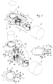
- Figure 1 is a perspective view from above showing a motor-compressor unit connecting rod according to the invention;
- Figure 2 is an exploded perspective view of the connecting rod of Figure 1;
- Figure 3 is a side view of part of the connecting rod of Figure 1;
- and
- Figure 4 is a plan view of the part shown in Figure 3.
- With reference to said figures, a connecting rod of a motor-compressor unit is indicated overall by 1 and comprises a first and a
second element 2 and 3 which cooperate with each other. Thefirst element 2 comprises an annular portion 4 to be mounted on the usual motor-compressorunit drive shaft 5 driven by a known electric motor, not shown. From theouter surface 6 of the portion 4 there projects a portion 7 to cooperate with oneend 8 of the second element 3. This latter has anannular end 10 to cooperate with the usual motor-compressor unit piston, which is connected to saidend 10 in known manner. - More specifically, the portion 7 comprises a substantially straight
first part 13 joined to saidsurface 6, and a widenedsecond part 14 with transverse dimensions greater than 13 and with atapered end 15. On this latter there is anelement 17 connected to aflat surface 18 of theelement 2 and projecting laterally therefrom and from theend 15. - The
end 8 of the second element 3 is fork-shaped and comprises twoarms 20 defining acompartment 21 of shape corresponding to the portion 7 of the first element. Saidarms 20 are therefore close together at theopen end 23 of thecompartment 21, then diverge substantially to the centre of the compartment and come together again at thatpart 25 of the element 3 which connects theend 8 to theannular end 10. -
Shoulders 30 rise from theflat surface 28 of theends 27 of saidarms 20, to cooperate with theends element 17 of said portion 7. - The
elements 2 and 3 of the connectingrod 1 are connected together by slidingly inserting the end 7 of thefirst element 2 into theend 8 of the second. Theshoulders 30 are then made to counteract theends element 17, while at the same time these latter rest on thepart 25 to block movement between said elements. - The counteraction of the
shoulders 30 on theends element 17 prevents accidental separation of the second element 3 from thefirst element 2. - The connection between the
elements 2 and 3 is made and then maintained without the use of any elastic connection material, so simplifying the construction of the connecting rod. - The
elements 2 and 3 can be disconnected in the opposite manner to that described for their connection, ie by elastically widening thearms 20 of theend 8 of the second element after moving theshoulders 30 away from the element 17 (by lowering them in the figures). - A particular embodiment of the invention has been described. Other embodiments are however possible, falling within the scope of the present document.
Claims (3)
- A motor-compressor unit comprising a drive shaft (5) rotating about its axis and driven by an electric motor, to said shaft (5) there being connected a connecting rod which is connected to a piston mobile within a cylinder, the connecting rod comprising two elements (2, 3) removably connected together, wherein the first element (2) is arranged to cooperate with said first shaft (5) and comprises a part (7) projecting radially outwards from an annular portion (4), said projecting part (7) comprising a first substantially straight portion (13) and a second widened portion (14), and said projecting part (7) tapering at its free end (15), and wherein the second element (3) is arranged to cooperate with the piston (11) and has a substantially fork-shaped end (8) with its arms (20) defining a compartment (21) of shape corresponding to the projecting part (7) of the first element (2), the connection between said first and second element (2, 3) being made by inserting said projecting part (7) of the first element (2) into the compartment (21) defined by the forked end (8) of the second element (3), characterised in that a stop and counteracting member (17) is connected to the tapered end (15) of said first element (2), and in that the arms (20) of the fork-shaped end (8) of the second element (3) carry shoulders (30) which rise from a flat surface (28) of said arms and are arranged to cooperate with ends (17A, 17B) of the stop member (17) which project from the projecting portion (7) of the first element (2).
- A motor-compressor unit as claimed in claim 1, characterised in that the stop member (17) projects laterally from the tapered end (15).
- A motor-compressor unit as claimed in claim 1 or 2, characterised in that the arms (20) of the fork-shaped end (8) of the second element (3) are adapted to be elastically widened.
Applications Claiming Priority (2)
| Application Number | Priority Date | Filing Date | Title |
|---|---|---|---|
| ITMI920904U | 1992-10-16 | ||
| IT000904 IT227105Y1 (en) | 1992-10-16 | 1992-10-16 | CONNECTING ROD FOR MOTOR-COMPRESSORS |
Publications (2)
| Publication Number | Publication Date |
|---|---|
| EP0592812A1 EP0592812A1 (en) | 1994-04-20 |
| EP0592812B1 true EP0592812B1 (en) | 1996-06-05 |
Family
ID=11362930
Family Applications (1)
| Application Number | Title | Priority Date | Filing Date |
|---|---|---|---|
| EP19930114478 Expired - Lifetime EP0592812B1 (en) | 1992-10-16 | 1993-09-09 | Connecting rod for motor-compressor units |
Country Status (5)
| Country | Link |
|---|---|
| EP (1) | EP0592812B1 (en) |
| BR (1) | BR9304255A (en) |
| DE (1) | DE69302984T2 (en) |
| ES (1) | ES2089660T3 (en) |
| IT (1) | IT227105Y1 (en) |
Families Citing this family (4)
| Publication number | Priority date | Publication date | Assignee | Title |
|---|---|---|---|---|
| CN100520094C (en) | 1996-11-26 | 2009-07-29 | 松下冷机株式会社 | Reciprocating compressor |
| ITPN20020040U1 (en) * | 2002-07-08 | 2004-01-08 | Zanussi Elettromecc | CONNECTED CONNECTING ROD FOR MOTOR-COMPRESSORS |
| KR100944967B1 (en) | 2003-11-03 | 2010-03-03 | 삼성광주전자 주식회사 | Hermetic compressor |
| KR101199983B1 (en) * | 2010-05-28 | 2012-11-12 | 주식회사코핸즈 | Air compressor having direct fork function |
Family Cites Families (5)
| Publication number | Priority date | Publication date | Assignee | Title |
|---|---|---|---|---|
| US3465952A (en) * | 1968-03-26 | 1969-09-09 | Jonesmith Co Inc | Piston and connecting rod structure for air compressors |
| US4631003A (en) * | 1983-08-15 | 1986-12-23 | Spray-All, Inc. | Fluid medium compressor and user apparatus |
| BR8501182A (en) * | 1985-03-08 | 1986-10-14 | Brasil Compressores Sa | ALTERNATIVE PISTON COMPRESSOR FOR SMALL REFRIGERATION MACHINES AND THEIR ASSEMBLY PROCESS |
| BR8707047A (en) * | 1987-12-17 | 1989-07-18 | Brasil Compressores Sa | IMPROVEMENT IN ALTERNATIVE PISTON COMPRESSOR FOR SMALL REFRIGERATION MACHINES AND ITS ASSEMBLY PROCESS |
| IT1245062B (en) * | 1991-04-12 | 1994-09-13 | Aspera Srl | CONNECTING ROD FOR SMALL ALTERNATIVE MACHINES, IN PARTICULAR FOR COMPRESSORS FOR REFRIGERATORS |
-
1992
- 1992-10-16 IT IT000904 patent/IT227105Y1/en active IP Right Grant
-
1993
- 1993-09-09 DE DE1993602984 patent/DE69302984T2/en not_active Expired - Lifetime
- 1993-09-09 EP EP19930114478 patent/EP0592812B1/en not_active Expired - Lifetime
- 1993-09-09 ES ES93114478T patent/ES2089660T3/en not_active Expired - Lifetime
- 1993-10-15 BR BR9304255A patent/BR9304255A/en not_active IP Right Cessation
Also Published As
| Publication number | Publication date |
|---|---|
| DE69302984D1 (en) | 1996-07-11 |
| DE69302984T2 (en) | 1996-10-31 |
| EP0592812A1 (en) | 1994-04-20 |
| BR9304255A (en) | 1994-04-19 |
| ES2089660T3 (en) | 1996-10-01 |
| ITMI920904V0 (en) | 1992-10-16 |
| IT227105Y1 (en) | 1997-09-15 |
| ITMI920904U1 (en) | 1994-04-16 |
Similar Documents
| Publication | Publication Date | Title |
|---|---|---|
| US4352586A (en) | Linkage system | |
| US4206657A (en) | Power driven tool having a reciprocating shaft arrangement and method of assembly | |
| AU681825B2 (en) | Vibrating compressor | |
| US7895723B2 (en) | Joint press set | |
| EP3821697B1 (en) | Pruning machine | |
| JP2578495B2 (en) | Reciprocating piston compressor and method of assembling the same | |
| CN109249413A (en) | A kind of combination clamping device | |
| KR900009230Y1 (en) | Motor | |
| EP0592812A1 (en) | Connecting rod for motor-compressor units | |
| CA1107701A (en) | Hermetic compressor assembly including torque reaction leaf spring means | |
| CN112621172A (en) | Assembling method and assembling device for cross axle universal joint | |
| JP2009083035A (en) | Circlip mounting tool | |
| CN113601208A (en) | Clamp for steering knuckle | |
| RU2154535C2 (en) | Method of assembly of gas centrifuge | |
| EP0608506B1 (en) | Compressor section in an easily assembled motor-compressor unit | |
| EP0929763A1 (en) | A piston assembly of a hydraulic radial piston-type machine | |
| EP3623626A1 (en) | Cartridge-type vane pump and pump device | |
| EP0071408A1 (en) | Diaphragm assembly | |
| CN219310580U (en) | Handle semi-finished product equipment | |
| CN109794747B (en) | Clamp spring assembly machine | |
| CN217800062U (en) | Clutch sealing ring installation tool with detection function | |
| WO1998044280A1 (en) | A connecting-rod/piston unit for small reciprocating machines and a motor-driven compressor or a similar reciprocating machine comprising the unit | |
| US4647006A (en) | Rotary electrically actuated device | |
| CN218416132U (en) | Convenient assembly fixture for ball bearing of tail shaft of hydraulic plunger pump | |
| US20070040456A1 (en) | Linear compressor, particularly refrigerant compressor |
Legal Events
| Date | Code | Title | Description |
|---|---|---|---|
| PUAI | Public reference made under article 153(3) epc to a published international application that has entered the european phase |
Free format text: ORIGINAL CODE: 0009012 |
|
| AK | Designated contracting states |
Kind code of ref document: A1 Designated state(s): DE ES FR GB |
|
| 17P | Request for examination filed |
Effective date: 19941013 |
|
| 17Q | First examination report despatched |
Effective date: 19941209 |
|
| GRAH | Despatch of communication of intention to grant a patent |
Free format text: ORIGINAL CODE: EPIDOS IGRA |
|
| GRAA | (expected) grant |
Free format text: ORIGINAL CODE: 0009210 |
|
| AK | Designated contracting states |
Kind code of ref document: B1 Designated state(s): DE ES FR GB |
|
| ET | Fr: translation filed | ||
| REF | Corresponds to: |
Ref document number: 69302984 Country of ref document: DE Date of ref document: 19960711 |
|
| REG | Reference to a national code |
Ref country code: ES Ref legal event code: FG2A Ref document number: 2089660 Country of ref document: ES Kind code of ref document: T3 |
|
| REG | Reference to a national code |
Ref country code: ES Ref legal event code: FG2A Ref document number: 2089660 Country of ref document: ES Kind code of ref document: T3 |
|
| PLBE | No opposition filed within time limit |
Free format text: ORIGINAL CODE: 0009261 |
|
| 26N | No opposition filed | ||
| REG | Reference to a national code |
Ref country code: FR Ref legal event code: TP |
|
| REG | Reference to a national code |
Ref country code: GB Ref legal event code: 732E |
|
| REG | Reference to a national code |
Ref country code: GB Ref legal event code: IF02 |
|
| PGFP | Annual fee paid to national office [announced via postgrant information from national office to epo] |
Ref country code: GB Payment date: 20040817 Year of fee payment: 12 |
|
| PGFP | Annual fee paid to national office [announced via postgrant information from national office to epo] |
Ref country code: ES Payment date: 20050804 Year of fee payment: 13 |
|
| PG25 | Lapsed in a contracting state [announced via postgrant information from national office to epo] |
Ref country code: GB Free format text: LAPSE BECAUSE OF NON-PAYMENT OF DUE FEES Effective date: 20050909 |
|
| GBPC | Gb: european patent ceased through non-payment of renewal fee |
Effective date: 20050909 |
|
| REG | Reference to a national code |
Ref country code: FR Ref legal event code: ST Effective date: 20080531 |
|
| PG25 | Lapsed in a contracting state [announced via postgrant information from national office to epo] |
Ref country code: FR Free format text: LAPSE BECAUSE OF NON-PAYMENT OF DUE FEES Effective date: 20071001 |
|
| PGFP | Annual fee paid to national office [announced via postgrant information from national office to epo] |
Ref country code: FR Payment date: 20060929 Year of fee payment: 14 |
|
| REG | Reference to a national code |
Ref country code: ES Ref legal event code: FD2A Effective date: 20070910 |
|
| PG25 | Lapsed in a contracting state [announced via postgrant information from national office to epo] |
Ref country code: ES Free format text: LAPSE BECAUSE OF NON-PAYMENT OF DUE FEES Effective date: 20070910 |
|
| PGFP | Annual fee paid to national office [announced via postgrant information from national office to epo] |
Ref country code: DE Payment date: 20090922 Year of fee payment: 17 |
|
| REG | Reference to a national code |
Ref country code: DE Ref legal event code: R119 Ref document number: 69302984 Country of ref document: DE Effective date: 20110401 |
|
| PG25 | Lapsed in a contracting state [announced via postgrant information from national office to epo] |
Ref country code: DE Free format text: LAPSE BECAUSE OF NON-PAYMENT OF DUE FEES Effective date: 20110401 |