EP0592525B1 - Injection moulding of thermoplastic polymers - Google Patents
Injection moulding of thermoplastic polymers Download PDFInfo
- Publication number
- EP0592525B1 EP0592525B1 EP92914338A EP92914338A EP0592525B1 EP 0592525 B1 EP0592525 B1 EP 0592525B1 EP 92914338 A EP92914338 A EP 92914338A EP 92914338 A EP92914338 A EP 92914338A EP 0592525 B1 EP0592525 B1 EP 0592525B1
- Authority
- EP
- European Patent Office
- Prior art keywords
- polymer
- mould
- cooling
- cavity
- gas
- Prior art date
- Legal status (The legal status is an assumption and is not a legal conclusion. Google has not performed a legal analysis and makes no representation as to the accuracy of the status listed.)
- Expired - Lifetime
Links
- 238000001746 injection moulding Methods 0.000 title claims abstract description 11
- 229920001169 thermoplastic Polymers 0.000 title claims abstract description 11
- 229920000642 polymer Polymers 0.000 claims abstract description 37
- 238000001816 cooling Methods 0.000 claims abstract description 30
- 238000000034 method Methods 0.000 claims abstract description 24
- 238000000465 moulding Methods 0.000 claims description 24
- 239000000463 material Substances 0.000 claims description 6
- 239000002861 polymer material Substances 0.000 claims description 3
- 230000000007 visual effect Effects 0.000 abstract 1
- 230000000694 effects Effects 0.000 description 8
- 230000008901 benefit Effects 0.000 description 5
- 239000000155 melt Substances 0.000 description 5
- 238000012856 packing Methods 0.000 description 5
- 239000004033 plastic Substances 0.000 description 5
- 239000000047 product Substances 0.000 description 3
- 238000007788 roughening Methods 0.000 description 3
- 230000000052 comparative effect Effects 0.000 description 2
- 238000002347 injection Methods 0.000 description 2
- 239000007924 injection Substances 0.000 description 2
- 239000012466 permeate Substances 0.000 description 2
- 239000004416 thermosoftening plastic Substances 0.000 description 2
- 230000009286 beneficial effect Effects 0.000 description 1
- 230000015572 biosynthetic process Effects 0.000 description 1
- 238000005422 blasting Methods 0.000 description 1
- 238000004891 communication Methods 0.000 description 1
- 239000000498 cooling water Substances 0.000 description 1
- 238000010586 diagram Methods 0.000 description 1
- 239000007788 liquid Substances 0.000 description 1
- 239000012768 molten material Substances 0.000 description 1
- 230000001105 regulatory effect Effects 0.000 description 1
- 238000009757 thermoplastic moulding Methods 0.000 description 1
Images


Classifications
-
- B—PERFORMING OPERATIONS; TRANSPORTING
- B29—WORKING OF PLASTICS; WORKING OF SUBSTANCES IN A PLASTIC STATE IN GENERAL
- B29C—SHAPING OR JOINING OF PLASTICS; SHAPING OF MATERIAL IN A PLASTIC STATE, NOT OTHERWISE PROVIDED FOR; AFTER-TREATMENT OF THE SHAPED PRODUCTS, e.g. REPAIRING
- B29C37/00—Component parts, details, accessories or auxiliary operations, not covered by group B29C33/00 or B29C35/00
- B29C37/005—Compensating volume or shape change during moulding, in general
-
- B—PERFORMING OPERATIONS; TRANSPORTING
- B29—WORKING OF PLASTICS; WORKING OF SUBSTANCES IN A PLASTIC STATE IN GENERAL
- B29C—SHAPING OR JOINING OF PLASTICS; SHAPING OF MATERIAL IN A PLASTIC STATE, NOT OTHERWISE PROVIDED FOR; AFTER-TREATMENT OF THE SHAPED PRODUCTS, e.g. REPAIRING
- B29C45/00—Injection moulding, i.e. forcing the required volume of moulding material through a nozzle into a closed mould; Apparatus therefor
- B29C45/17—Component parts, details or accessories; Auxiliary operations
- B29C45/1703—Introducing an auxiliary fluid into the mould
- B29C45/174—Applying a pressurised fluid to the outer surface of the injected material inside the mould cavity, e.g. for preventing shrinkage marks
-
- B—PERFORMING OPERATIONS; TRANSPORTING
- B29—WORKING OF PLASTICS; WORKING OF SUBSTANCES IN A PLASTIC STATE IN GENERAL
- B29C—SHAPING OR JOINING OF PLASTICS; SHAPING OF MATERIAL IN A PLASTIC STATE, NOT OTHERWISE PROVIDED FOR; AFTER-TREATMENT OF THE SHAPED PRODUCTS, e.g. REPAIRING
- B29C45/00—Injection moulding, i.e. forcing the required volume of moulding material through a nozzle into a closed mould; Apparatus therefor
- B29C45/0025—Preventing defects on the moulded article, e.g. weld lines, shrinkage marks
Definitions
- the invention relates to a process for the injection moulding of thermoplastic polymers.
- molten polymer material is injected into one or more cavities defined by separable mould parts, allowed to cool and solidify and extracted after the mould parts are separated.
- Thermoplastic polymers shrink on cooling and this causes sink marks apparent on the surface at regions where the article is thicker than in neighbouring regions.
- a difficulty with the above described method is that air flow through the melt is restricted and often cut off at narrow regions of the melt since these usually solidify first.
- the method is therefore not suitable for some forms of article and in particular may not be suitable for multi-cavity moulds for moulding multiple parts since variation in air passage profile would cause inequality in part material.
- a method of injection moulding which consists in injecting molten thermoplastic polymer material into a cavity defined by separable mould parts, allowing the material to cool and solidify in a cooling phase, separating the mould parts and extracting the solidified material, wherein, during the cooling phase gas is applied under pressure via apertures in the cavity wall to form a pressurised gas layer between the cooling polymer and the cavity wall, characterised in that the gas is distributed to selected places in the cavity wall via prepared surface portions which are roughened to provide micro-channels in the wall.
- the gas is air.
- a moulding tool for the injection moulding of thermoplastic polymer articles, the tool having at least one cavity defined by separable mould parts, gas ducts within at least one of the mould parts for introducing gas into the cavity via the cavity wall whereby a gas layer may be introduced between the cavity wall and polymer cooling in the cavity; characterised in that in use the gas is distributed to selected places in the cavity wall via prepared surface portions which are roughened to provide micro-channels.
- the screw top has a generally cylindrical body 1 which is internally threaded at 2 and which has a domed head 3 with flats 4 around the periphery.
- Figure 2 is a comparative cross-sectional view which shows on the right hand side the screw top when conventionally moulded and on the left-hand side the screw top when moulded using the present invention. The right-hand side shows the effect (exaggerated in the drawing) of shrinkage during cooling. Since the threaded region 2 is of alternating wall thickness there is differential shrinkage during cooling. The thicker parts shrunk more than the thinner parts and since shrinking is inward the effect is to give slight depressions at 5. These are sink marks.
- FIG. 3 there is shown a moulding tool embodying the invention which is designed for moulding the screw top of Figures 1 and 2.
- the tool comprises a central core 6 which has threads 7 and which defines the internal shape of the screw top.
- the core 6 sits within an outer split mould 8 the inner surface of which defines the external shape of the screw top.
- the cavity 9 defined between the core 6 and the outer mould 8 is filled with molten thermoplastic polymer via an internal central channel C by a screw injector (not shown).
- a screw injector not shown
- Air ducts 10 are provided in the core 6 and these are coupled by control valves (not shown) to a high pressure air supply. Typically the air pressure can be 1-300 bar.
- the ducts vent into the cavity at positions chosen for the desired effect of establishing a thin layer of pressurised air between the core and the cooling polymer, the air being applied during the cooling phase.
- the vents are less than 0.001" in width.
- the liquid polymer does not block such small passageways.
- the core is roughened at chosen places 11 by grit blasting. The roughening provides micro-channels through which the air can permeate.
- Air communication to the chosen areas is ensured by situating a vent in each chosen area or by roughening the region between a vent and the chosen area to conduct air.
- a vent in each chosen area or by roughening the region between a vent and the chosen area to conduct air.
- it is found beneficial to apply air in two stages, firstly a short low-pressure stage and secondly a larger high-pressure stage.
- this gas pressure is to pressurise the polymer, substantially equal to the gas pressure. In many moulded components this will cause polymer to flow back through the component "feed gate” unless prevented by either a gate valve or a machine nozzle shut-off valve. Both systems are available as proprietary injection moulding equipment.
- Figure 4 shows detail of the tool of Figure 3, specifically the roughened regions 11 on the mould core (inner mould part) 26. These are surrounded by smooth boundary regions 12. At these smooth boundaries the cooling polymer forms seals which contain the pressurised air layers.
- the mould cavity (the outer mould part) 27 is smooth.
- the injected plastic is shown at 28.
- the effect of the air is to urge the polymer away from the core.
- the amount of air and its pressure is closely regulated so that the air is just sufficient to maintain an outward pressure of the polymer against the wall of the outer mould 8 despite the tendency of the polymer to shrink.
- the air acts as a spring which accommodates to the shrinkage effect and keeps the polymer in intimate contact with the wall of mould 8. This has two effects. Firstly, the formation of sink marks is inhibited. Secondly, cooling of the polymer takes place via the outer mould 8.
- FIG. 5 there is shown schematically a moulding machine which has a tool of the kind shown in Figure 3 but with multiple mould cavities 13.
- the mould cavities are defined between a fixed platen 14 and a moving platen 15.
- a machine screw and barrel plasticising/injection system 16 is provided for injecting the plastic material at 17 via a shut-off nozzle 18.
- High pressure air is supplied to the air conduit system 19 via an air solenoid valve 20 from an air compressor 21.
- An air reservoir 22 is provided to reduce pressure fluctuations.
- Valve 20 has a low air pressure input 25 which may be used for the low pressure phase described above. Accelerated cooling is achieved by means of cooling ducts 23 in the outer (moving) mould part.
- a pipe system 24 supplies cooling water to the ducts 23 and removes it therefrom.
- thermoplastic mouldings this process offers an economic route to obtaining effectively 'Sink Free' precision mouldings. Also, stresses within the parts are even and low with consequential low warpage.
- the plasticising element of the cycle can start significantly earlier in the machine cycle, giving the opportunity to shorten the cycle accordingly.
- this cycle time saving would have a proportional effect on the part cost.
- the size (and therefore cost) of the moulding machine is determined by the 'packing pressure' necessary to minimise 'sinks' on the part.
- This packing pressure tends to be relatively high, because as the part cools, it becomes progressively more difficult to inject molten material into features far away from the 'gate'.
- the maximum duration required for packing is 2.0 seconds, and therefore the melt is relatively hot, and the pressure can be a minimum.
- the melt is relatively hot, and the pressure can be a minimum.
- the size of this mark becomes a critical quality parameter.
- the gate diameter is substantially controlled by the length of the "packing phase” required, so that the gate does not freeze. However, when using this process this consideration no longer applies and the gate diameter may be the minimum necessary to fill the part.
Landscapes
- Engineering & Computer Science (AREA)
- Manufacturing & Machinery (AREA)
- Mechanical Engineering (AREA)
- Moulds For Moulding Plastics Or The Like (AREA)
- Injection Moulding Of Plastics Or The Like (AREA)
- Graft Or Block Polymers (AREA)
- Compositions Of Macromolecular Compounds (AREA)
Abstract
Description
- The invention relates to a process for the injection moulding of thermoplastic polymers. In such a process, molten polymer material is injected into one or more cavities defined by separable mould parts, allowed to cool and solidify and extracted after the mould parts are separated. Thermoplastic polymers shrink on cooling and this causes sink marks apparent on the surface at regions where the article is thicker than in neighbouring regions.
- Sink marks seriously detract from the appearance of moulded thermoplastic articles and efforts have been made to obviate them. One process injects high pressure air into the partly solidified melt and it is found that the air forms channels within the melt and permeates principally to relatively thick regions of the article. Here the air is locked under high pressure and exerts an outward force which inhibits external sinking as the melt cools.
- A difficulty with the above described method is that air flow through the melt is restricted and often cut off at narrow regions of the melt since these usually solidify first. The method is therefore not suitable for some forms of article and in particular may not be suitable for multi-cavity moulds for moulding multiple parts since variation in air passage profile would cause inequality in part material.
- An alternative method is shown in patent specification US 3345687 where air under pressure is introduced between one mould surface and the semi-molten polymer of the part being moulded. This method uses low air pressure. For current commercial products and polymers very much greater air pressures would be required and the use of higher pressures introduces the difficulties that air can leak from between the part being moulded and the mould parting line and polymer can be forced back through the cavity gate point. The present invention seeks to provide an improved injection moulding process.
- According to one aspect of the invention there is provided a method of injection moulding which consists in injecting molten thermoplastic polymer material into a cavity defined by separable mould parts, allowing the material to cool and solidify in a cooling phase, separating the mould parts and extracting the solidified material, wherein, during the cooling phase gas is applied under pressure via apertures in the cavity wall to form a pressurised gas layer between the cooling polymer and the cavity wall, characterised in that the gas is distributed to selected places in the cavity wall via prepared surface portions which are roughened to provide micro-channels in the wall. Preferably the gas is air.
- It is normal to make the cavity walls smooth but it is found that by roughening the walls slightly in selected areas the gas is provided with micro-channels along which it can flow to establish the required gas layer. Furthermore, the distribution of gas via the micro-channels is limited by polymer seals formed between the cooling polymer and smooth-walled boundaries bounding the prepared surface portions. In this way a very thin high-pressure gas layer can be established where desired. In practice a gas layer will be positioned to urge the solidifying polymer against the opposing wall of the cavity where sink marks would otherwise be experienced. Clearly, it is possible to apply gas where required in the mould and the invention is applicable to multi-cavity moulding as well as single cavity moulding.
- According to another aspect of the invention there is provided a moulding tool for the injection moulding of thermoplastic polymer articles, the tool having at least one cavity defined by separable mould parts, gas ducts within at least one of the mould parts for introducing gas into the cavity via the cavity wall whereby a gas layer may be introduced between the cavity wall and polymer cooling in the cavity; characterised in that in use the gas is distributed to selected places in the cavity wall via prepared surface portions which are roughened to provide micro-channels.
- There are other disadvantages in conventional injection moulding techniques. For example, generally hollow thick-walled articles are formed by defining a cavity between a central core and an outer mould. In cooling, the polymer shrinks on to the core and loses thermal contact with the outer mould. Consequently, heat must be extracted via the core and because the core size is small and thermal access is restricted the cooling rate is limited. In turn this limits the cycle time of the moulding process. The present invention provides an improvement, since it is possible to arrange that the gas layer is provided between the core and the cooling polymer, thereby retaining thermal contact between the polymer and the outer mould as the polymer cools. Heat can be extracted efficiently and quickly via the outer mould instead of via the core.
- The invention will further be described with reference to the accompanying drawings, of which:-
- Figure 1 is a perspective view of a thermoplastics screw top for a container;
- Figure 2 is a comparative cross-sectional view of the screw top of Figure 1;
- Figure 3 is a cross-sectional view of a moulding tool embodying the invention for moulding a screw top of the kind shown in Figures 1 and 2,
- Figure 4 is a detail view of part of the tool of Figure 3; and
- Figure 5 is a schematic diagram of a moulding machine embodying the invention.
- Referring to Figure 1 the screw top has a generally
cylindrical body 1 which is internally threaded at 2 and which has adomed head 3 withflats 4 around the periphery. Figure 2 is a comparative cross-sectional view which shows on the right hand side the screw top when conventionally moulded and on the left-hand side the screw top when moulded using the present invention. The right-hand side shows the effect (exaggerated in the drawing) of shrinkage during cooling. Since the threadedregion 2 is of alternating wall thickness there is differential shrinkage during cooling. The thicker parts shrunk more than the thinner parts and since shrinking is inward the effect is to give slight depressions at 5. These are sink marks. - Referring now to Figure 3 there is shown a moulding tool embodying the invention which is designed for moulding the screw top of Figures 1 and 2. The tool comprises a
central core 6 which hasthreads 7 and which defines the internal shape of the screw top. Thecore 6 sits within anouter split mould 8 the inner surface of which defines the external shape of the screw top. Thecavity 9 defined between thecore 6 and theouter mould 8 is filled with molten thermoplastic polymer via an internal central channel C by a screw injector (not shown). There is then a cooling phase during which the polymer is allowed to cool and solidify. During the cooling phase the injection pressure is held in order to pack more polymer into the tool as shrinkage takes place. -
Air ducts 10 are provided in thecore 6 and these are coupled by control valves (not shown) to a high pressure air supply. Typically the air pressure can be 1-300 bar. The ducts vent into the cavity at positions chosen for the desired effect of establishing a thin layer of pressurised air between the core and the cooling polymer, the air being applied during the cooling phase. The vents are less than 0.001" in width. The liquid polymer does not block such small passageways. In order to allow air to flow along the surface of the core, the core is roughened at chosenplaces 11 by grit blasting. The roughening provides micro-channels through which the air can permeate. Air communication to the chosen areas is ensured by situating a vent in each chosen area or by roughening the region between a vent and the chosen area to conduct air. In practice it is found beneficial to apply air in two stages, firstly a short low-pressure stage and secondly a larger high-pressure stage. - The effect of this gas pressure is to pressurise the polymer, substantially equal to the gas pressure. In many moulded components this will cause polymer to flow back through the component "feed gate" unless prevented by either a gate valve or a machine nozzle shut-off valve. Both systems are available as proprietary injection moulding equipment.
- Figure 4 shows detail of the tool of Figure 3, specifically the roughened
regions 11 on the mould core (inner mould part) 26. These are surrounded bysmooth boundary regions 12. At these smooth boundaries the cooling polymer forms seals which contain the pressurised air layers. The mould cavity (the outer mould part) 27 is smooth. The injected plastic is shown at 28. - The effect of the air is to urge the polymer away from the core. The amount of air and its pressure is closely regulated so that the air is just sufficient to maintain an outward pressure of the polymer against the wall of the
outer mould 8 despite the tendency of the polymer to shrink. In other words the air acts as a spring which accommodates to the shrinkage effect and keeps the polymer in intimate contact with the wall ofmould 8. This has two effects. Firstly, the formation of sink marks is inhibited. Secondly, cooling of the polymer takes place via theouter mould 8. - Referring now to Figure 5 there is shown schematically a moulding machine which has a tool of the kind shown in Figure 3 but with
multiple mould cavities 13. The mould cavities are defined between a fixedplaten 14 and a movingplaten 15. A machine screw and barrel plasticising/injection system 16 is provided for injecting the plastic material at 17 via a shut-offnozzle 18. - High pressure air is supplied to the
air conduit system 19 via anair solenoid valve 20 from anair compressor 21. Anair reservoir 22 is provided to reduce pressure fluctuations.Valve 20 has a lowair pressure input 25 which may be used for the low pressure phase described above. Accelerated cooling is achieved by means of coolingducts 23 in the outer (moving) mould part. Apipe system 24 supplies cooling water to theducts 23 and removes it therefrom. - Because of the more rapid cooling possible via the outer mould than conventionally via the core, improvements in cycle time may be achieved. For example, typical figures are given below for (a) conventional practice and (b) the process of the invention:-
- (a) Typical Standard Cycle. (Numbers - seconds) Overall Cycle of 16 seconds shown
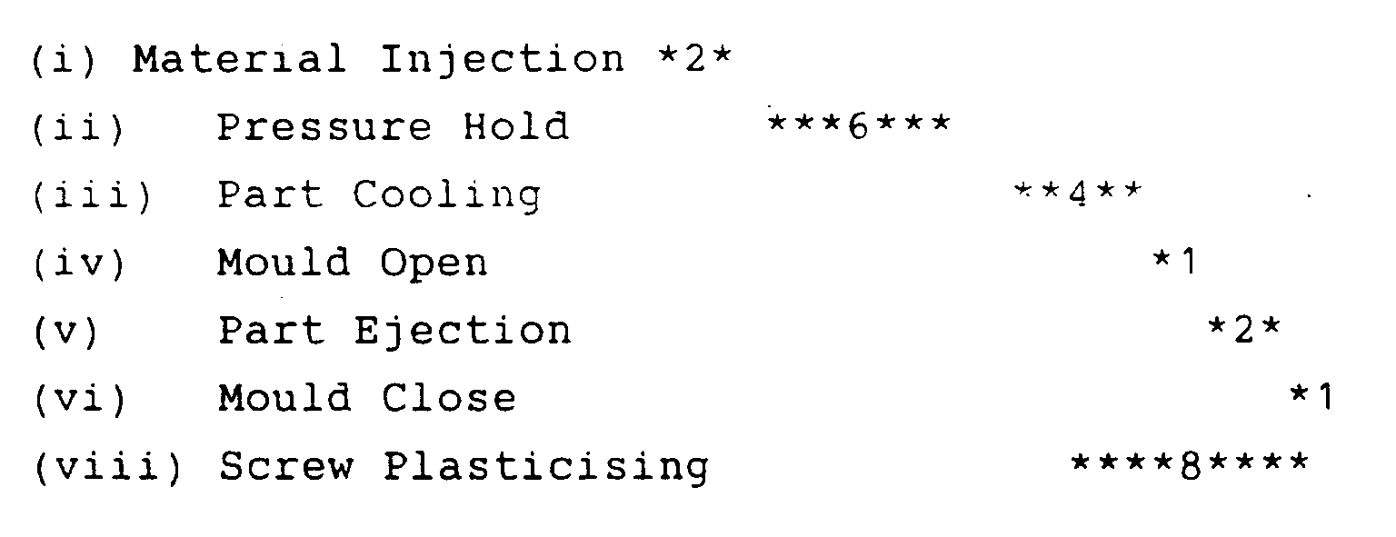
- (b) With use of the Figure 3 tool Assuming a cycle time of 14 seconds
- It has been noted that a further advantage of this moulding process is that the polymer stress above, is fundamentally equal all over the component. This is unusual with conventional moulding techniques, where it is understood that in order to minimise "sink marks", molten polymer is continuously injected into the semi-molten core of the part as it cools and shrinks away from the cavity walls. This process element is normally referred to as the "pressure hold or packing phase" and is understood to induce unequal and sometimes severe stresses into the component. These unequal internal stresses result in warpage of the part, once it is removed from the mould, and is a large element of part quality rejections. Thus any process having substantially equal stresses and low warpage will have significant economic and quality benefits.
- Some of the benefits of the invention may be summarised as follows:-
- For thermoplastic mouldings, this process offers an economic route to obtaining effectively 'Sink Free' precision mouldings. Also, stresses within the parts are even and low with consequential low warpage.
- With innovative tooling design, parts can be manufactured with relatively simple tooling, that would be only possible, if at all, by expensive tooling running on slow cycles. Freedom in part design is allowed since requirements to hide sink marks are relaxed.
- Many injection moulding cycles are limited by the time necessary to plasticise the molten charge for the following 'shot'.
- Using the invention it can be seen, that the plasticising element of the cycle can start significantly earlier in the machine cycle, giving the opportunity to shorten the cycle accordingly. In many medium to high volume parts, this cycle time saving would have a proportional effect on the part cost.
- In many moulding systems, the size (and therefore cost) of the moulding machine is determined by the 'packing pressure' necessary to minimise 'sinks' on the part. This packing pressure tends to be relatively high, because as the part cools, it becomes progressively more difficult to inject molten material into features far away from the 'gate'.
- Using the invention, however, the maximum duration required for packing is 2.0 seconds, and therefore the melt is relatively hot, and the pressure can be a minimum. Thus, it allows an increase in the size of part which can be moulded on a given sized machine with associated reduction in costs to the customer.
- Because internal moulding stresses are reduced and there is less likelihood of the mould to flash it is possible to use less expensive tooling.
- Where the moulding "gate mark" is in a highly visible position, the size of this mark becomes a critical quality parameter. The gate diameter is substantially controlled by the length of the "packing phase" required, so that the gate does not freeze. However, when using this process this consideration no longer applies and the gate diameter may be the minimum necessary to fill the part.
- Using conventional moulding techniques it has been found to be extremely difficult to predict the precise shrinkage value for each discrete element of a part. Since this shrinkage value is influenced by the following plastic conditions during moulding:-
- (a) plastic temperature profile;
- (b) plastic stress profile; and
- (c) whether the element is free to shrink, or is restrained by the mould core or cavity.
- Since using this process will reduce the variation of all of these parameters it is expected that this shrinkage value will show significantly less variation, and will therefore be easier to predict.
- The invention is not restricted to the details of the foregoing example.

Claims (8)
- A method of injection moulding which consists in injecting molten thermoplastic polymer material into a cavity (9) defined by separable mould parts (6, 8), allowing the material to cool and solidify in a cooling phase, separating the mould parts (6, 8) and extracting the solidified material, wherein, during the cooling phase gas is applied under pressure via apertures (10) in the cavity wall (6) to form a pressurised gas layer between the cooling polymer and the cavity wall (6), characterised in that the gas is distributed to selected places in the cavity wall (6) via prepared surface portions (11) which are roughened to provide micro-channels in the wall (6).
- A method as claimed in Claim 1 wherein the distribution of gas via the micro-channels is limited by polymer seals formed between the cooling polymer (28) and smooth-walled boundaries (12) bounding the prepared surface portions (11).
- A method as claimed in Claim 1 or Claim 2 wherein the mould (6, 8) is a multi-cavity mould (13).
- A method as claimed in any preceding Claim wherein the mould comprises a mould core (6) and an outer mould (8) and the gas layer is provided between the core (6) and the cooling polymer (28) thereby retaining thermal contact between the polymer (28) and the outer mould (8) as the polymer (28) cools.
- A moulding tool for the injection moulding of thermoplastic polymer articles, the tool having at least one cavity (9) defined by separable mould parts (6, 8), gas ducts (10) within at least one of the mould parts (6, 8) for introducing gas into the cavity (9) via the cavity wall (26) whereby a gas layer may be introduced between the cavity wall (26) and polymer (28) cooling in the cavity (9), characterised in that in use the gas is distributed to selected places in the cavity wall (26) via prepared surface portions (11) which are roughened to provide micro-channels.
- A moulding tool as claimed in Claim 5 wherein the prepared surface portions (11) are bounded by smooth regions (12).
- A moulding tool as claimed in Claim 5 or Claim 6 wherein the tool comprises a core (6) and an outer mould (8) and the ducts (10) and prepared surface portions (11) are arranged so that the gas layer is provided between the core (6) and the polymer (28).
- A moulding tool as claimed in Claim 7 wherein cooling means (23, 24) are provided to extract heat from the outer mould (15).
Applications Claiming Priority (3)
| Application Number | Priority Date | Filing Date | Title |
|---|---|---|---|
| GB9114324 | 1991-07-03 | ||
| GB919114324A GB9114324D0 (en) | 1991-07-03 | 1991-07-03 | Injection moulding of thermoplastic polymers |
| PCT/GB1992/001206 WO1993001039A1 (en) | 1991-07-03 | 1992-07-03 | Injection moulding of thermoplastic polymers |
Publications (2)
| Publication Number | Publication Date |
|---|---|
| EP0592525A1 EP0592525A1 (en) | 1994-04-20 |
| EP0592525B1 true EP0592525B1 (en) | 1996-10-23 |
Family
ID=10697725
Family Applications (1)
| Application Number | Title | Priority Date | Filing Date |
|---|---|---|---|
| EP92914338A Expired - Lifetime EP0592525B1 (en) | 1991-07-03 | 1992-07-03 | Injection moulding of thermoplastic polymers |
Country Status (12)
| Country | Link |
|---|---|
| US (1) | US6071463A (en) |
| EP (1) | EP0592525B1 (en) |
| JP (1) | JP3169382B2 (en) |
| AT (1) | ATE144455T1 (en) |
| AU (1) | AU2243992A (en) |
| CA (1) | CA2112747C (en) |
| DE (1) | DE69214817T2 (en) |
| DK (1) | DK0592525T3 (en) |
| ES (1) | ES2093264T3 (en) |
| GB (1) | GB9114324D0 (en) |
| GR (1) | GR3022197T3 (en) |
| WO (1) | WO1993001039A1 (en) |
Cited By (2)
| Publication number | Priority date | Publication date | Assignee | Title |
|---|---|---|---|---|
| DE19949539C1 (en) * | 1999-10-14 | 2001-03-01 | Battenfeld Gmbh | Injection molding method to produce intersecting, reinforced wall sections avoiding collapse, effects movement of transition region plastic towards intersection point by fluid injection |
| US6294126B1 (en) | 1997-10-04 | 2001-09-25 | Battenfeld Gmbh | Process for controlling gas blanket extent in plastics injection molding |
Families Citing this family (24)
| Publication number | Priority date | Publication date | Assignee | Title |
|---|---|---|---|---|
| US5458846A (en) * | 1988-12-05 | 1995-10-17 | Carroll; Robert E. | Method of injection molding |
| GB9202165D0 (en) * | 1992-02-01 | 1992-03-18 | Pearson Terence C | Gas-assisted injection moulding method and apparatus |
| US5439365A (en) * | 1992-03-23 | 1995-08-08 | Icp Systems, Inc. | Apparatus for fluid compression of injection molded plastic material |
| US6403014B1 (en) | 1992-03-23 | 2002-06-11 | Incoe Corporation | Method for fluid compression of injection molded plastic material |
| GB2278308A (en) * | 1993-05-11 | 1994-11-30 | Gas Injection Ltd | Gas assisted injection moulding method and apparatus |
| JP3290011B2 (en) * | 1993-10-22 | 2002-06-10 | 株式会社青木固研究所 | Preform molding method in injection stretch blow molding |
| AU687431B2 (en) * | 1993-10-22 | 1998-02-26 | A. K. Technical Laboratory, Inc. | Method of molding preform in injection stretch blow molding |
| DE19516290C2 (en) * | 1995-05-04 | 1997-09-11 | Battenfeld Gmbh | Method and device for injection molding plastic objects |
| US5716560A (en) * | 1995-09-14 | 1998-02-10 | Icp Systems, Inc. | Gas assisted injection molding combining internal and external gas pressures |
| DE19735031C2 (en) * | 1997-08-13 | 2000-09-21 | Battenfeld Gmbh | Method and device for injection molding plastic objects |
| DE19855929C2 (en) * | 1998-12-04 | 2000-10-26 | Brocke Kg I B S | Method and device for producing molded parts |
| DE10006359C1 (en) * | 2000-02-12 | 2001-10-31 | Brocke Kg I B S | Production of decorative materials from leather or textiles is carried out in two-part mold, pressurized gas being applied to material surface, beginning at start of filling molding cavity, at latest |
| US6830716B2 (en) * | 2001-06-06 | 2004-12-14 | Fuji Photo Film Co., Ltd. | Method of removing extraneous matter from injection mold |
| EP1633786A4 (en) * | 2002-10-09 | 2007-07-25 | Rinat Neuroscience Corp | Methods of treating alzheimer s disease using antibodies directed against amyloid beta peptide and compositions thereof |
| US20050129888A1 (en) * | 2003-12-10 | 2005-06-16 | Kwon Hyuk T. | Process for making cosmetic containers having a transparent thermoplastic outer wall |
| JP3838372B2 (en) * | 2004-06-08 | 2006-10-25 | トヨタ自動車株式会社 | Injection molding method and injection molding apparatus |
| GEP20115195B (en) * | 2004-07-30 | 2011-04-11 | Rinat Neuroscience Corp | Antibodies directed against amyloid-beta peptide and use thereof |
| PE20061323A1 (en) | 2005-04-29 | 2007-02-09 | Rinat Neuroscience Corp | ANTIBODIES TARGETED AGAINST AMYLOID BETA PEPTIDE AND METHODS USING THEM |
| US8841378B2 (en) * | 2007-07-02 | 2014-09-23 | Bridgestone Corporation | Polymeric particles and processes for preparation of polymeric particles that involve molding |
| DE102008022421B3 (en) * | 2008-05-07 | 2009-11-19 | Blach Verwaltungs Gmbh & Co. Kg | Extruder drives |
| JP6346119B2 (en) * | 2015-03-27 | 2018-06-20 | 株式会社ニフコ | Skin clip |
| US11572536B2 (en) | 2015-05-11 | 2023-02-07 | Simplinext Sa | Well inserts with brittle membranes |
| EP3558623B1 (en) * | 2016-12-22 | 2024-09-04 | Modi Consulting and Investments Pty Ltd | Moulding process having active force coupled cooling |
| CN110480966A (en) * | 2018-05-15 | 2019-11-22 | 泰科电子(上海)有限公司 | Injection mould cooling system |
Family Cites Families (27)
| Publication number | Priority date | Publication date | Assignee | Title |
|---|---|---|---|---|
| US3345687A (en) * | 1964-06-10 | 1967-10-10 | Gen Electric | Injection molding apparatus |
| FR2105498A5 (en) * | 1970-09-09 | 1972-04-28 | Meca Ste Internale Const | Shoe sole mould - giving smooth surfaced products and allowing ejection without use of release agents |
| DE2235994A1 (en) * | 1971-10-23 | 1973-05-03 | Ts Lab Stex | METHOD AND DEVICE FOR INJECTION MOLDING OF POLYMERS |
| DE2501314A1 (en) * | 1975-01-15 | 1976-07-22 | Roehm Gmbh | INJECTION MOLDING OF HOLLOW MOLDED PARTS MADE OF THERMOPLASTIC PLASTICS, IN PARTICULAR FOR THE CONSTRUCTION SECTOR |
| US4164523A (en) * | 1976-09-09 | 1979-08-14 | Robert Hanning | Method of injection-molding and cooling of shaped synthetic-resin bodies |
| US4177238A (en) * | 1977-12-14 | 1979-12-04 | Logic Devices, Inc. | Fluid cooling of injection molded plastic articles |
| US4474717A (en) * | 1982-05-24 | 1984-10-02 | Lang Fastener Corporation | Method of making a twin-wall internally corrugated plastic structural part with a smooth non-cellular skin |
| GB2139549A (en) * | 1983-05-11 | 1984-11-14 | James Watson Hendry | Injection moulding |
| GB2139548B (en) * | 1983-05-11 | 1986-11-19 | James Watson Hendry | Injection moulding |
| GB2158002B (en) * | 1984-05-04 | 1987-06-17 | Peerless Foam Moulding Co | Injection moulding |
| CA1292348C (en) * | 1986-05-19 | 1991-11-26 | Indra K. Baxi | Method for injection molding, apparatus therefor and moldings produced thereby |
| GB8706204D0 (en) * | 1987-03-16 | 1987-04-23 | Peerless Cinpres Ltd | Injection moulding apparatus |
| JPH0788025B2 (en) * | 1987-04-28 | 1995-09-27 | 三菱瓦斯化学株式会社 | Manufacturing method of synthetic resin molded product having uneven wall reinforcement structure |
| US4944910A (en) * | 1987-07-09 | 1990-07-31 | Michael Ladney | Method of molding thermoplastic material |
| GB8722620D0 (en) * | 1987-09-25 | 1987-11-04 | Cinpres Ltd | Injection moulding |
| US5069859A (en) * | 1987-12-16 | 1991-12-03 | Milad Limited Partnership | Method of injection molding with pressurized-fluid assist |
| US4913644A (en) * | 1988-04-15 | 1990-04-03 | Michael Ladney | System for making a hollow-shaped body from molten resin by injection molding |
| GB2217644A (en) * | 1988-04-22 | 1989-11-01 | Cinpres Ltd | Injection moulding |
| US5225141A (en) * | 1988-07-11 | 1993-07-06 | Milad Limited Partnership | Process for injection molding a hollow plastic article |
| US5098637A (en) * | 1988-07-11 | 1992-03-24 | Milad Limited Partnership | Process for injection molding and hollow plastic article produced thereby |
| ATE155728T1 (en) * | 1988-12-05 | 1997-08-15 | Robert E Carroll | INJECTION MOLDING PROCESS |
| US5069858A (en) * | 1989-09-18 | 1991-12-03 | Milad Limited Partnership | Method for the use of gas assistance in the molding of plastic articles |
| GB2241464A (en) * | 1990-03-01 | 1991-09-04 | Cinpres Ltd | Moulding rackets |
| US5028377A (en) * | 1990-03-05 | 1991-07-02 | Michael Ladney | Method for injection molding plastic article with gas-assistance |
| US5137680A (en) * | 1990-07-16 | 1992-08-11 | Milad Limited Partnership | Method of injection molding utilizing pressurized fluid source within a chamber in a mold |
| US5110533A (en) * | 1990-11-07 | 1992-05-05 | Milad Limited Partnership | Method for the use of gas assistance in the molding of plastic articles to enhance surface quality |
| US5232711A (en) * | 1991-06-06 | 1993-08-03 | Melea Limited | Apparatus for injection molding with pressurized fluid assist in the mold |
-
1991
- 1991-07-03 GB GB919114324A patent/GB9114324D0/en active Pending
-
1992
- 1992-07-03 EP EP92914338A patent/EP0592525B1/en not_active Expired - Lifetime
- 1992-07-03 WO PCT/GB1992/001206 patent/WO1993001039A1/en not_active Ceased
- 1992-07-03 DK DK92914338.6T patent/DK0592525T3/en active
- 1992-07-03 ES ES92914338T patent/ES2093264T3/en not_active Expired - Lifetime
- 1992-07-03 US US08/178,263 patent/US6071463A/en not_active Expired - Fee Related
- 1992-07-03 AU AU22439/92A patent/AU2243992A/en not_active Abandoned
- 1992-07-03 DE DE69214817T patent/DE69214817T2/en not_active Expired - Fee Related
- 1992-07-03 AT AT92914338T patent/ATE144455T1/en not_active IP Right Cessation
- 1992-07-03 CA CA002112747A patent/CA2112747C/en not_active Expired - Fee Related
- 1992-07-03 JP JP50207993A patent/JP3169382B2/en not_active Expired - Fee Related
-
1996
- 1996-12-31 GR GR960402280T patent/GR3022197T3/en unknown
Cited By (2)
| Publication number | Priority date | Publication date | Assignee | Title |
|---|---|---|---|---|
| US6294126B1 (en) | 1997-10-04 | 2001-09-25 | Battenfeld Gmbh | Process for controlling gas blanket extent in plastics injection molding |
| DE19949539C1 (en) * | 1999-10-14 | 2001-03-01 | Battenfeld Gmbh | Injection molding method to produce intersecting, reinforced wall sections avoiding collapse, effects movement of transition region plastic towards intersection point by fluid injection |
Also Published As
| Publication number | Publication date |
|---|---|
| GR3022197T3 (en) | 1997-03-31 |
| ATE144455T1 (en) | 1996-11-15 |
| JPH07505585A (en) | 1995-06-22 |
| DE69214817T2 (en) | 1997-02-27 |
| WO1993001039A1 (en) | 1993-01-21 |
| US6071463A (en) | 2000-06-06 |
| CA2112747A1 (en) | 1993-01-21 |
| ES2093264T3 (en) | 1996-12-16 |
| AU2243992A (en) | 1993-02-11 |
| DE69214817D1 (en) | 1996-11-28 |
| EP0592525A1 (en) | 1994-04-20 |
| DK0592525T3 (en) | 1997-04-21 |
| CA2112747C (en) | 2002-05-14 |
| JP3169382B2 (en) | 2001-05-21 |
| GB9114324D0 (en) | 1991-08-21 |
Similar Documents
| Publication | Publication Date | Title |
|---|---|---|
| US6071463A (en) | Method and apparatus for preventing sink marks in the injection moulding of thermoplastic polymers | |
| US4963312A (en) | Injection molding method for plastic materials | |
| US5047183B1 (en) | Method of injection molding articles of thermoplastic materials | |
| US4601870A (en) | Injection molding process | |
| US4701292A (en) | Method for pressure molding objects of different resins | |
| EP0830931B1 (en) | On-demand fast cycle mold | |
| US5232654A (en) | Injection molding method for manufacturing a thermoplastic part free from sink marks using a void inducing member | |
| US5762861A (en) | Method and apparatus for producing hollow plastic objects with pressurized gas injection after overflow cut-off | |
| EP0321117B2 (en) | Method and system for localized fluid-assisted injection molding and body formed thereby | |
| CA2649177C (en) | Two-piece bottom insert | |
| WO1990006220A1 (en) | Injection mold method and apparatus | |
| CA2219941C (en) | Method and system for injection molding utilizing a variable volume spill cavity and article produced thereby | |
| US6666999B1 (en) | Gas assisted moulding | |
| US5458846A (en) | Method of injection molding | |
| US5304341A (en) | Injection molding apparatus and method having in-cavity control of plastics and gas flow rates | |
| JP4383673B2 (en) | Injection molding apparatus having a molding core with a reverse taper | |
| US6855280B2 (en) | Method for injection molding of plastic materials using gas holding pressure in mold | |
| EP0751858B1 (en) | Method and mould for injection-moulding of a product, and product manufactured by the method | |
| EP1127674A3 (en) | Method and apparatus for injection moulding articles having at least one hollow section | |
| EP0958120B1 (en) | A process in the manufacturing of a plastic product | |
| WO1998053975A1 (en) | Injection moulding of thermoplastic polymers | |
| GB2322094A (en) | Method and apparatus for injection moulding | |
| GB2343651A (en) | Plastics moulding | |
| HK1006210B (en) | Method of injection molding a thermoplastic resin and a mold for injection molding |
Legal Events
| Date | Code | Title | Description |
|---|---|---|---|
| PUAI | Public reference made under article 153(3) epc to a published international application that has entered the european phase |
Free format text: ORIGINAL CODE: 0009012 |
|
| 17P | Request for examination filed |
Effective date: 19931223 |
|
| AK | Designated contracting states |
Kind code of ref document: A1 Designated state(s): AT BE CH DE DK ES FR GB GR IT LI LU NL SE |
|
| 17Q | First examination report despatched |
Effective date: 19950518 |
|
| GRAG | Despatch of communication of intention to grant |
Free format text: ORIGINAL CODE: EPIDOS AGRA |
|
| GRAH | Despatch of communication of intention to grant a patent |
Free format text: ORIGINAL CODE: EPIDOS IGRA |
|
| GRAH | Despatch of communication of intention to grant a patent |
Free format text: ORIGINAL CODE: EPIDOS IGRA |
|
| GRAA | (expected) grant |
Free format text: ORIGINAL CODE: 0009210 |
|
| AK | Designated contracting states |
Kind code of ref document: B1 Designated state(s): AT BE CH DE DK ES FR GB GR IT LI LU NL SE |
|
| REF | Corresponds to: |
Ref document number: 144455 Country of ref document: AT Date of ref document: 19961115 Kind code of ref document: T |
|
| ITF | It: translation for a ep patent filed | ||
| ET | Fr: translation filed | ||
| REG | Reference to a national code |
Ref country code: CH Ref legal event code: NV Representative=s name: ISLER & PEDRAZZINI AG PATENTANWAELTE |
|
| REF | Corresponds to: |
Ref document number: 69214817 Country of ref document: DE Date of ref document: 19961128 |
|
| REG | Reference to a national code |
Ref country code: ES Ref legal event code: FG2A Ref document number: 2093264 Country of ref document: ES Kind code of ref document: T3 |
|
| REG | Reference to a national code |
Ref country code: GR Ref legal event code: FG4A Free format text: 3022197 |
|
| REG | Reference to a national code |
Ref country code: DK Ref legal event code: T3 |
|
| PLBE | No opposition filed within time limit |
Free format text: ORIGINAL CODE: 0009261 |
|
| STAA | Information on the status of an ep patent application or granted ep patent |
Free format text: STATUS: NO OPPOSITION FILED WITHIN TIME LIMIT |
|
| 26N | No opposition filed | ||
| REG | Reference to a national code |
Ref country code: GB Ref legal event code: IF02 |
|
| PGFP | Annual fee paid to national office [announced via postgrant information from national office to epo] |
Ref country code: BE Payment date: 20030602 Year of fee payment: 12 |
|
| PGFP | Annual fee paid to national office [announced via postgrant information from national office to epo] |
Ref country code: FR Payment date: 20030604 Year of fee payment: 12 |
|
| PGFP | Annual fee paid to national office [announced via postgrant information from national office to epo] |
Ref country code: DE Payment date: 20030627 Year of fee payment: 12 |
|
| PGFP | Annual fee paid to national office [announced via postgrant information from national office to epo] |
Ref country code: LU Payment date: 20030630 Year of fee payment: 12 |
|
| PGFP | Annual fee paid to national office [announced via postgrant information from national office to epo] |
Ref country code: ES Payment date: 20030708 Year of fee payment: 12 |
|
| PGFP | Annual fee paid to national office [announced via postgrant information from national office to epo] |
Ref country code: SE Payment date: 20030716 Year of fee payment: 12 |
|
| PGFP | Annual fee paid to national office [announced via postgrant information from national office to epo] |
Ref country code: DK Payment date: 20030718 Year of fee payment: 12 |
|
| PGFP | Annual fee paid to national office [announced via postgrant information from national office to epo] |
Ref country code: CH Payment date: 20030721 Year of fee payment: 12 |
|
| PGFP | Annual fee paid to national office [announced via postgrant information from national office to epo] |
Ref country code: AT Payment date: 20030724 Year of fee payment: 12 |
|
| PGFP | Annual fee paid to national office [announced via postgrant information from national office to epo] |
Ref country code: NL Payment date: 20030731 Year of fee payment: 12 |
|
| PGFP | Annual fee paid to national office [announced via postgrant information from national office to epo] |
Ref country code: GR Payment date: 20030901 Year of fee payment: 12 |
|
| PG25 | Lapsed in a contracting state [announced via postgrant information from national office to epo] |
Ref country code: LU Free format text: LAPSE BECAUSE OF NON-PAYMENT OF DUE FEES Effective date: 20040703 Ref country code: AT Free format text: LAPSE BECAUSE OF NON-PAYMENT OF DUE FEES Effective date: 20040703 |
|
| PG25 | Lapsed in a contracting state [announced via postgrant information from national office to epo] |
Ref country code: SE Free format text: LAPSE BECAUSE OF NON-PAYMENT OF DUE FEES Effective date: 20040704 |
|
| PG25 | Lapsed in a contracting state [announced via postgrant information from national office to epo] |
Ref country code: ES Free format text: LAPSE BECAUSE OF NON-PAYMENT OF DUE FEES Effective date: 20040705 |
|
| PG25 | Lapsed in a contracting state [announced via postgrant information from national office to epo] |
Ref country code: LI Free format text: LAPSE BECAUSE OF NON-PAYMENT OF DUE FEES Effective date: 20040731 Ref country code: CH Free format text: LAPSE BECAUSE OF NON-PAYMENT OF DUE FEES Effective date: 20040731 Ref country code: BE Free format text: LAPSE BECAUSE OF NON-PAYMENT OF DUE FEES Effective date: 20040731 |
|
| PG25 | Lapsed in a contracting state [announced via postgrant information from national office to epo] |
Ref country code: DK Free format text: LAPSE BECAUSE OF NON-PAYMENT OF DUE FEES Effective date: 20040802 |
|
| BERE | Be: lapsed |
Owner name: *KONTOR MOULDING SYSTEMS LTD Effective date: 20040731 |
|
| PG25 | Lapsed in a contracting state [announced via postgrant information from national office to epo] |
Ref country code: NL Free format text: LAPSE BECAUSE OF NON-PAYMENT OF DUE FEES Effective date: 20050201 Ref country code: DE Free format text: LAPSE BECAUSE OF NON-PAYMENT OF DUE FEES Effective date: 20050201 |
|
| PG25 | Lapsed in a contracting state [announced via postgrant information from national office to epo] |
Ref country code: GR Free format text: LAPSE BECAUSE OF NON-PAYMENT OF DUE FEES Effective date: 20050203 |
|
| REG | Reference to a national code |
Ref country code: DK Ref legal event code: EBP |
|
| EUG | Se: european patent has lapsed | ||
| REG | Reference to a national code |
Ref country code: CH Ref legal event code: PL |
|
| PG25 | Lapsed in a contracting state [announced via postgrant information from national office to epo] |
Ref country code: FR Free format text: LAPSE BECAUSE OF NON-PAYMENT OF DUE FEES Effective date: 20050331 |
|
| NLV4 | Nl: lapsed or anulled due to non-payment of the annual fee |
Effective date: 20050201 |
|
| REG | Reference to a national code |
Ref country code: FR Ref legal event code: ST |
|
| PGFP | Annual fee paid to national office [announced via postgrant information from national office to epo] |
Ref country code: GB Payment date: 20050621 Year of fee payment: 14 |
|
| PG25 | Lapsed in a contracting state [announced via postgrant information from national office to epo] |
Ref country code: IT Free format text: LAPSE BECAUSE OF NON-PAYMENT OF DUE FEES;WARNING: LAPSES OF ITALIAN PATENTS WITH EFFECTIVE DATE BEFORE 2007 MAY HAVE OCCURRED AT ANY TIME BEFORE 2007. THE CORRECT EFFECTIVE DATE MAY BE DIFFERENT FROM THE ONE RECORDED. Effective date: 20050703 |
|
| REG | Reference to a national code |
Ref country code: ES Ref legal event code: FD2A Effective date: 20040705 |
|
| PG25 | Lapsed in a contracting state [announced via postgrant information from national office to epo] |
Ref country code: GB Free format text: LAPSE BECAUSE OF NON-PAYMENT OF DUE FEES Effective date: 20060703 |
|
| GBPC | Gb: european patent ceased through non-payment of renewal fee |
Effective date: 20060703 |
|
| BERE | Be: lapsed |
Owner name: *KONTOR MOULDING SYSTEMS LTD Effective date: 20040731 |