EP0592459B1 - Actuator assembly - Google Patents
Actuator assembly Download PDFInfo
- Publication number
- EP0592459B1 EP0592459B1 EP92910819A EP92910819A EP0592459B1 EP 0592459 B1 EP0592459 B1 EP 0592459B1 EP 92910819 A EP92910819 A EP 92910819A EP 92910819 A EP92910819 A EP 92910819A EP 0592459 B1 EP0592459 B1 EP 0592459B1
- Authority
- EP
- European Patent Office
- Prior art keywords
- actuators
- linkage
- actuator assembly
- assembly according
- pair
- Prior art date
- Legal status (The legal status is an assumption and is not a legal conclusion. Google has not performed a legal analysis and makes no representation as to the accuracy of the status listed.)
- Expired - Lifetime
Links
- 238000000034 method Methods 0.000 description 4
- 230000000712 assembly Effects 0.000 description 2
- 238000000429 assembly Methods 0.000 description 2
- 238000006073 displacement reaction Methods 0.000 description 2
- 230000007246 mechanism Effects 0.000 description 2
- 230000000704 physical effect Effects 0.000 description 1
- 238000004088 simulation Methods 0.000 description 1
- 230000003068 static effect Effects 0.000 description 1
- 230000000007 visual effect Effects 0.000 description 1
Images

Classifications
-
- G—PHYSICS
- G09—EDUCATION; CRYPTOGRAPHY; DISPLAY; ADVERTISING; SEALS
- G09B—EDUCATIONAL OR DEMONSTRATION APPLIANCES; APPLIANCES FOR TEACHING, OR COMMUNICATING WITH, THE BLIND, DEAF OR MUTE; MODELS; PLANETARIA; GLOBES; MAPS; DIAGRAMS
- G09B9/00—Simulators for teaching or training purposes
- G09B9/02—Simulators for teaching or training purposes for teaching control of vehicles or other craft
- G09B9/08—Simulators for teaching or training purposes for teaching control of vehicles or other craft for teaching control of aircraft, e.g. Link trainer
- G09B9/12—Motion systems for aircraft simulators
- G09B9/14—Motion systems for aircraft simulators controlled by fluid actuated piston or cylinder ram
Definitions
- the present invention relates to an actuator assembly, particularly but not exclusively applicable to the support of motion platforms for vehicle simulators.
- Vehicle simulators are widely used in training or entertainment applications.
- One major area of use is in the training of aircraft pilots.
- a trainee pilot sits in a mock cockpit and views an image visible through the cockpit windows.
- the mock cockpit is supported on a motion platform so that the physical effects of vehicle motion can be simulated to suppiement the simulation of aircraft motion represented by the visual image.
- the mock cockpit is supported on six hydraulic actuators.
- the hydraulic actuators are connected between three pivots on the underside of the platform and three pivots on a support base beneath the platform.
- each platform pivot is connected to two actuators which are in turn connected to respective ones of a pair of the support base pivots.
- the pivots are arranged in a hexagonal shape, the platform pivots and support base pivots alternating around the periphery of the hexagon.
- This actuator system provides for movement about 6 axes providing translational (vertical, longitudinal or lateral) and rotational (pitch, roll and heave) displacements.
- the conventional actuator system works well for standard sized flight simulators. If the size of the motion platform of the flight simulator is increased, the size of the conventional actuator system must be increased accordingly. This causes a problem when it is desired to use a large motion platform suitable for supporting for example a representation of a passenger aircraft fuselage to be used for emergency evacuation training, where the actuators would have to be very long.
- a three axis system has been proposed having three servo-controlled actuators and various methods of constraint, for example, "scissors", “hanging links” and cascade mechanisms where one axis is built upon another.
- constraint for example, "scissors", "hanging links” and cascade mechanisms where one axis is built upon another.
- Such three axis systems provide for pitch, heave and roll, but the methods of constraint and cascade mechanisms are complex and costly.
- an actuator assembly comprising a pair of interconnected extensible actuators, a linkage constrained to move with the actuators such that differences in extension of the actuators cause a change in position of the linkage, and means for detecting changes in position of the linkage.
- the linkage comprises an elongate rod which may be mounted so as to be equi-distant between the actuators.
- a sleeve may be slidably mounted on the rod and connected to a pair of arms, each of the arms being connected to a respective one of the pair of actuators.
- the arms are pivotally connected to the actuators and the sleeve.
- the actuators may be pivotally connected together, and may be pivotally mounted on respective pivots located on a supporting surface to define a triangular structure.
- the rod may be pivotally mounted on the supporting surface between the actuator pivots.
- a warning output may be generated in the event of the linkage being displaced from the datum position.
- a motion system platform may be supported on one or more of the actuator assemblies. Preferably there are three actuator assemblies.
- a vehicle simulator may be mounted on the platform.
- the triangular structure formed by the two hydraulic actuators and the supporting surface may be maintained isosceles at all times. This ensures that the actuators are extended and retracted In phase and with equal amplitude.
- a conventional six axis motion system comprises a motion platform 1 which is positioned on six hydraulic actuators 2 to 7.
- the six actuators 2 to 7 are connected at their lower ends to three pivot points 8, 9, 10 which are securely mounted on a supporting floor 11.
- the upper ends of the actuators are connected to pivot points 12, 13, 14 mounted on the underside of the motion platform 1.
- a trainee pilot is indicated by the figure 15.
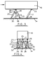
- the illustrated motion system comprises a motion platform 16 positioned on six hydraulic actuators 17 to 22.
- the motion platform is of generally rectangular shape and has dimensions typically of 16.8m (55ft) x 6.7m (22ft) x 5.5m (18ft).
- the actuators 17 to 22 are of a standard form as used in conventional six-axis systems, with a piston 23 located in an actuator body 24, in which the piston 23 is slidable, and are grouped into 3 pairs. Each pair of actuators is connected at upper ends of the pistons 23 to a pivot point 25, 26, 27 mounted on the underside of the motion platform 16. Pivot point 25 is located towards one end of the motion platform mid-way between the side edges of the platform.
- Pivot points 26, 27 are located opposite one another at the edges of the platform towards the other end of the platform from pivot point 25. Pivot points 25, 26, 27 are all approximately equi-distant from the centre of mass of the platform.
- the lower ends of actuators 17 to 22 are connected to six pivot points 28 to 33 which are securely mounted on a supporting floor 34. Each pair of actuators forms an isosceles triangle with the floor 34.
- Actuators 17 and 18 are pivoted to pivot point 25 and pivot points 28 and 29. Pivot points 28 and 29 are situated further towards the centre of mass of the platform than pivot point 25, so that actuators 17 and 18 are inclined at an angle to the vertical.
- Pivot points 30 and 32 are located below the edge of the platform.
- Pivot points 31 and 33 are located beneath the platform, further towards the end of the platform and further towards the centre of the platform than pivot points 26 and 27. Thus actuators 19, 20, 21 and 22 are inclined at an angle to the vertical.
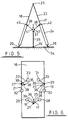
- a control rod 35 is provided for each pair of actuators.
- the control rod is pivoted to the floor at a pivot point 36 mid-way between the actuators.
- the control rod is provided with a sleeve 37, slidable on the control rod.
- Two arms 38, 39 are pivoted to the sleeve 37 at pivot points 40, 41.
- the other end of each arm 38, 39 is pivoted to pivot points 42, 43 on the actuator body 24.
- Pivot points 42, 43 are situated at an upper end of the actuator body 24, in a position facing the control rod 35.
- the control rods are inclined at an angle to the vertical because the actuators are so inclined.
- the arms 38, 39 cause the sleeve 37 to slide up or down the control rod 35. If extension or retraction of the pair of actuators is equal, there is no lateral force on the control rod 35. The control rod thus remains in the same position, spaced equi-distant between the actuators. If the extension of the pair of actuators are unequal, a lateral force if applied to the control rod via the arms 38, 39, and the control rod pivots about pivot point 36. Movement of the control rod 35 is utilised to initiate actions as required to remedy the imbalance in extension of the actuators. For example, the system could be shut down, feedback could be applied to a control loop, or hydraulic flow to or from the actuators could be controlled, depending on the situation.
- the triangle formed by a pair of actuators is free to rotate about a line joining the pivot points between the actuators and the supporting surface (for example, pivot points 28, 29), in response to movement of the other pairs of actuators.
- the control rod would also pivot about this line, without causing a lateral force to be exerted on the rod.
- the positions of the control rod 35 give an immediate indication of any difference between the lengths of the associated pairs of actuators.
- extensions of the pairs of actuators will be locked in amplitude and phase using conventional servo control methods, but in the event of failure of such control methods the control rods 35 will indicate failure and enable appropriate actions to be taken. High levels of system security and safety can therefore be achieved.
- the sleeve 37 is linked to the pivot points 42 and 43 and controls the angular position of the control rod 35.
- a telescopic or otherwise extensible rod could be connected at one end to the mid-point between the pivots 28 and 29 of Figure 5 and at the other end to the pivot 25. If the two jacks were intended to be of equal length at all times, the angular position of the telescopic control rod would be constant in all normal conditions, and therefore any displacement of the control rod would indicate a problem.
Landscapes
- Engineering & Computer Science (AREA)
- Theoretical Computer Science (AREA)
- Aviation & Aerospace Engineering (AREA)
- Business, Economics & Management (AREA)
- Physics & Mathematics (AREA)
- Educational Administration (AREA)
- Educational Technology (AREA)
- General Physics & Mathematics (AREA)
- Transmission Devices (AREA)
- Invalid Beds And Related Equipment (AREA)
- Mechanical Control Devices (AREA)
Abstract
Description
- The present invention relates to an actuator assembly, particularly but not exclusively applicable to the support of motion platforms for vehicle simulators.
- Vehicle simulators are widely used in training or entertainment applications. One major area of use is in the training of aircraft pilots.
- In a typical aircraft flight simulator (see for example US-A-3 295 224) a trainee pilot sits in a mock cockpit and views an image visible through the cockpit windows. Often the mock cockpit is supported on a motion platform so that the physical effects of vehicle motion can be simulated to suppiement the simulation of aircraft motion represented by the visual image. Typically the mock cockpit is supported on six hydraulic actuators. The hydraulic actuators are connected between three pivots on the underside of the platform and three pivots on a support base beneath the platform. Thus each platform pivot is connected to two actuators which are in turn connected to respective ones of a pair of the support base pivots. In plan view, the pivots are arranged in a hexagonal shape, the platform pivots and support base pivots alternating around the periphery of the hexagon. This actuator system provides for movement about 6 axes providing translational (vertical, longitudinal or lateral) and rotational (pitch, roll and heave) displacements.
- The conventional actuator system works well for standard sized flight simulators. If the size of the motion platform of the flight simulator is increased, the size of the conventional actuator system must be increased accordingly. This causes a problem when it is desired to use a large motion platform suitable for supporting for example a representation of a passenger aircraft fuselage to be used for emergency evacuation training, where the actuators would have to be very long.
- The problem of large actuator size with large motion platforms can be addressed by widening the system base (ie providing six support base pivots so as to move the pairs of actuators further apart) and reducing the actuators maximum extensions. Such an arrangement would cause problems of over-angling however, that is to say the ends of the platform could strike the support base.
- In some large motion platform systems, acceptable performances can be achieved with systems having three degrees of freedom. A three axis system has been proposed having three servo-controlled actuators and various methods of constraint, for example, "scissors", "hanging links" and cascade mechanisms where one axis is built upon another. Such three axis systems provide for pitch, heave and roll, but the methods of constraint and cascade mechanisms are complex and costly.
- It is an object of the present invention to provide an actuator assembly which can be built from conventional actuator components to provide a three axis motion platform support system.
- According to the present invention there is provided an actuator assembly comprising a pair of interconnected extensible actuators, a linkage constrained to move with the actuators such that differences in extension of the actuators cause a change in position of the linkage, and means for detecting changes in position of the linkage.
- Preferably the linkage comprises an elongate rod which may be mounted so as to be equi-distant between the actuators. A sleeve may be slidably mounted on the rod and connected to a pair of arms, each of the arms being connected to a respective one of the pair of actuators. Preferably the arms are pivotally connected to the actuators and the sleeve. The actuators may be pivotally connected together, and may be pivotally mounted on respective pivots located on a supporting surface to define a triangular structure. The rod may be pivotally mounted on the supporting surface between the actuator pivots.
- Preferably means are provided to control the actuators such that the linkage is maintained in a datum position. A warning output may be generated in the event of the linkage being displaced from the datum position.
- A motion system platform may be supported on one or more of the actuator assemblies. Preferably there are three actuator assemblies. A vehicle simulator may be mounted on the platform.
- Thus, the triangular structure formed by the two hydraulic actuators and the supporting surface may be maintained isosceles at all times. This ensures that the actuators are extended and retracted In phase and with equal amplitude.
- A specific embodiment of the present invention will now be described by wav of example, with reference to the accompanying drawings, in which;
- Figure 1
- is a schematic illustration of the basic components of a motion system of a conventional six axis motion platform;
- Figure 2
- is a schematic illustration of the arrangement of hydraulic actuators in a motion system of the type shown in Figure 1;
- Figure 3
- is a schematic illustration of the basic components of a motion system according to an embodiment of the present invention;
- Figure 4
- is a schematic illustration of the basic components shown in Figure 3 and viewed along the direction of the arrow of Figure 3;
- Figure 5
- is a schematic illustration of one of the pairs of hydraulic actuators shown in Figure 3: and
- Figure 6
- is a plan view of the positions of the hydraulic actuators in the embodiment of Figure 3.
- Referring to figures 1 and 2, a conventional six axis motion system comprises a motion platform 1 which is positioned on six
hydraulic actuators 2 to 7. The sixactuators 2 to 7 are connected at their lower ends to threepivot points floor 11. The upper ends of the actuators are connected topivot points - Referring now to figures 3, 4, 5 and 6, the illustrated motion system comprises a
motion platform 16 positioned on sixhydraulic actuators 17 to 22. The motion platform is of generally rectangular shape and has dimensions typically of 16.8m (55ft) x 6.7m (22ft) x 5.5m (18ft). Theactuators 17 to 22 are of a standard form as used in conventional six-axis systems, with apiston 23 located in anactuator body 24, in which thepiston 23 is slidable, and are grouped into 3 pairs. Each pair of actuators is connected at upper ends of thepistons 23 to apivot point motion platform 16.Pivot point 25 is located towards one end of the motion platform mid-way between the side edges of the platform.Pivot points pivot point 25.Pivot points actuators 17 to 22 are connected to sixpivot points 28 to 33 which are securely mounted on a supportingfloor 34. Each pair of actuators forms an isosceles triangle with thefloor 34.Actuators pivot point 25 andpivot points Pivot points pivot point 25, so thatactuators Pivot points Pivot points pivot points actuators - A
control rod 35 is provided for each pair of actuators. The control rod is pivoted to the floor at apivot point 36 mid-way between the actuators. The control rod is provided with asleeve 37, slidable on the control rod. Twoarms sleeve 37 at pivot points 40, 41. The other end of eacharm points actuator body 24. Pivot points 42, 43 are situated at an upper end of theactuator body 24, in a position facing thecontrol rod 35. The control rods are inclined at an angle to the vertical because the actuators are so inclined. - As the actuators are extended or retracted, the
arms sleeve 37 to slide up or down thecontrol rod 35. If extension or retraction of the pair of actuators is equal, there is no lateral force on thecontrol rod 35. The control rod thus remains in the same position, spaced equi-distant between the actuators. If the extension of the pair of actuators are unequal, a lateral force if applied to the control rod via thearms pivot point 36. Movement of thecontrol rod 35 is utilised to initiate actions as required to remedy the imbalance in extension of the actuators. For example, the system could be shut down, feedback could be applied to a control loop, or hydraulic flow to or from the actuators could be controlled, depending on the situation. - The triangle formed by a pair of actuators is free to rotate about a line joining the pivot points between the actuators and the supporting surface (for example, pivot points 28, 29), in response to movement of the other pairs of actuators. The control rod would also pivot about this line, without causing a lateral force to be exerted on the rod.
- Extending and retracting all six actuators simultaneously gives heave. Roll is obtained by extending
actuators actuators actuators actuators - Thus the positions of the
control rod 35 give an immediate indication of any difference between the lengths of the associated pairs of actuators. Generally, extensions of the pairs of actuators will be locked in amplitude and phase using conventional servo control methods, but in the event of failure of such control methods thecontrol rods 35 will indicate failure and enable appropriate actions to be taken. High levels of system security and safety can therefore be achieved. - In the arrangement illustrated in Figure 5, the
sleeve 37 is linked to the pivot points 42 and 43 and controls the angular position of thecontrol rod 35. Other arrangements are possible however. For example, a telescopic or otherwise extensible rod could be connected at one end to the mid-point between thepivots pivot 25. If the two jacks were intended to be of equal length at all times, the angular position of the telescopic control rod would be constant in all normal conditions, and therefore any displacement of the control rod would indicate a problem.
Claims (8)
- An actuator assembly comprising a pair of interconnected extensible actuators, characterised in that it further comprises a linkage constrained to move with the actuators such that differences in extension of the actuators cause a change in position of the linkage, and means for detecting changes in position of the linkage.
- An actuator assembly according to claim 1 wherein the linkage comprises an elongate rod mounted between the actuators.
- An actuator assembly according to claim 2, wherein a sleeve is slidably mounted on the rod and connected to a pair of arms, each of the arms being connected to a respective one of the pair of actuators.
- An actuator assembly according to claim 3, wherein the arms are pivotally connected to the actuators and the sleeve.
- An actuator assembly according to any preceding claim, wherein the actuators are pivotally connected together and pivotally mounted on respective pivots located on a supporting surface to define a triangular structure.
- An acutator assembly according to any preceding claim, wherein means are provided to control the actuators such that the linkage is maintained in a datum position.
- An actuator assembly according to claim 6, wherein a warning output is generated in the event of the linkage being displaced from the datum position.
- A motion system platform supported on at least one actuator assembly according to any preceding claim.
Applications Claiming Priority (3)
| Application Number | Priority Date | Filing Date | Title |
|---|---|---|---|
| GB9114124 | 1991-06-29 | ||
| GB919114124A GB9114124D0 (en) | 1991-06-29 | 1991-06-29 | Actuator assembly |
| PCT/GB1992/000984 WO1993000666A1 (en) | 1991-06-29 | 1992-06-01 | Actuator assembly |
Publications (2)
| Publication Number | Publication Date |
|---|---|
| EP0592459A1 EP0592459A1 (en) | 1994-04-20 |
| EP0592459B1 true EP0592459B1 (en) | 1996-02-07 |
Family
ID=10697593
Family Applications (1)
| Application Number | Title | Priority Date | Filing Date |
|---|---|---|---|
| EP92910819A Expired - Lifetime EP0592459B1 (en) | 1991-06-29 | 1992-06-01 | Actuator assembly |
Country Status (8)
| Country | Link |
|---|---|
| US (1) | US5511979A (en) |
| EP (1) | EP0592459B1 (en) |
| JP (1) | JPH06508699A (en) |
| AU (1) | AU1774792A (en) |
| CA (1) | CA2112564A1 (en) |
| DE (1) | DE69208253T2 (en) |
| GB (2) | GB9114124D0 (en) |
| WO (1) | WO1993000666A1 (en) |
Families Citing this family (15)
| Publication number | Priority date | Publication date | Assignee | Title |
|---|---|---|---|---|
| US5931739A (en) * | 1993-12-27 | 1999-08-03 | Moog Inc. | Fail-safe ride simulator |
| US5496220A (en) * | 1994-06-02 | 1996-03-05 | Brad Engstrand | Sensory simulator |
| AU7625294A (en) * | 1994-08-01 | 1996-03-04 | Technische Universiteit Delft | Method of manufacturing a motion simulator, and a motion simulator |
| US5975907A (en) * | 1998-04-06 | 1999-11-02 | Technische Universiteit Delft | Motion simulator with movable base plate |
| US6039653A (en) * | 1998-11-16 | 2000-03-21 | Engstrand; Brad | Apparatus, system and method for experiencing motion |
| GB2348915B (en) * | 1999-04-13 | 2001-03-21 | January Lech Bednarczyk | A clip for and method of attaching a replacement slate to a batten |
| NL1015672C2 (en) * | 2000-07-10 | 2002-01-11 | Lely Entpr Ag | Device for automatic milking of animals. |
| GB0127810D0 (en) * | 2001-11-21 | 2002-01-09 | Tilting Tees Ltd | Golf simulator |
| US7039512B2 (en) * | 2002-03-06 | 2006-05-02 | Vssl Commercial, Inc. | Active suspension for a marine platform |
| US8454366B2 (en) * | 2005-11-30 | 2013-06-04 | D-Box Technologies Inc. | Actuated support platform for video system |
| US8032238B2 (en) * | 2008-05-30 | 2011-10-04 | GM Global Technology Operations LLC | Mechanical system with an active materials-based actuator |
| US9410596B2 (en) * | 2011-11-04 | 2016-08-09 | Honeywell International Inc. | Mounting systems for structural members, fastening assemblies thereof, and vibration isolation systems including the same |
| US9475594B2 (en) | 2012-09-25 | 2016-10-25 | Honeywell International Inc. | Launch lock assemblies with reduced preload and spacecraft isolation systems including the same |
| AT516901B1 (en) * | 2015-03-06 | 2018-07-15 | Amst Systemtechnik Gmbh | Flight simulator and flight simulation method |
| CN114876992B (en) * | 2022-04-15 | 2023-04-07 | 重庆大学 | Active control Stewart vibration reduction platform based on magnetic transmission |
Family Cites Families (8)
| Publication number | Priority date | Publication date | Assignee | Title |
|---|---|---|---|---|
| US3295224A (en) * | 1964-12-07 | 1967-01-03 | Franklin Institute | Motion simulator |
| US3496650A (en) * | 1967-08-30 | 1970-02-24 | Us Navy | Air cushion proprioceptive motion system |
| US3577659A (en) * | 1969-08-06 | 1971-05-04 | Singer General Precision | Motion simulator actuator joint |
| US3967387A (en) * | 1974-10-21 | 1976-07-06 | Daniel Marchegiani | Motion simulator |
| US4268979A (en) * | 1978-08-17 | 1981-05-26 | The Singer Company | Method and apparatus to extend the bandwidth of buffeting in flight simulators |
| US4343610A (en) * | 1980-01-30 | 1982-08-10 | The Franklin Institute | Motion systems providing three or four degrees of freedom |
| US4536690A (en) * | 1982-10-19 | 1985-08-20 | Calspan Corporation | Tool-supporting self-propelled robot platform |
| GB2179605B (en) * | 1985-08-27 | 1988-11-16 | Singer Link Miles Ltd | Motion simulator |
-
1991
- 1991-06-29 GB GB919114124A patent/GB9114124D0/en active Pending
-
1992
- 1992-06-01 AU AU17747/92A patent/AU1774792A/en not_active Abandoned
- 1992-06-01 JP JP4509869A patent/JPH06508699A/en active Pending
- 1992-06-01 WO PCT/GB1992/000984 patent/WO1993000666A1/en not_active Ceased
- 1992-06-01 CA CA002112564A patent/CA2112564A1/en not_active Abandoned
- 1992-06-01 EP EP92910819A patent/EP0592459B1/en not_active Expired - Lifetime
- 1992-06-01 DE DE69208253T patent/DE69208253T2/en not_active Expired - Fee Related
- 1992-06-01 US US08/170,207 patent/US5511979A/en not_active Expired - Fee Related
-
1993
- 1993-12-16 GB GB9325791A patent/GB2272674B/en not_active Expired - Fee Related
Also Published As
| Publication number | Publication date |
|---|---|
| DE69208253T2 (en) | 1996-07-25 |
| GB9325791D0 (en) | 1994-03-02 |
| WO1993000666A1 (en) | 1993-01-07 |
| GB9114124D0 (en) | 1991-08-14 |
| CA2112564A1 (en) | 1992-12-30 |
| GB2272674B (en) | 1994-12-07 |
| JPH06508699A (en) | 1994-09-29 |
| GB2272674A (en) | 1994-05-25 |
| AU1774792A (en) | 1993-01-25 |
| DE69208253D1 (en) | 1996-03-21 |
| US5511979A (en) | 1996-04-30 |
| EP0592459A1 (en) | 1994-04-20 |
Similar Documents
| Publication | Publication Date | Title |
|---|---|---|
| US5511979A (en) | Motion system including actuator assembly | |
| US4343610A (en) | Motion systems providing three or four degrees of freedom | |
| CA2960554C (en) | Motion and vibration cuing system | |
| US8353199B1 (en) | Multi-degree-of-freedom test stand for unmanned air vehicles | |
| CN101528539B (en) | Joysticks for fly-by-wire flight control systems | |
| CA1064456A (en) | Aerofoils | |
| US5669773A (en) | Realistic motion ride simulator | |
| EP2870301B1 (en) | Adjustable structures | |
| US20080268404A1 (en) | Novel Aircraft Training Platform and Related Method of Operation | |
| KR102077969B1 (en) | Ground surface adaptive landing apparatus for vertical take-off and landing flight vehicle | |
| US3304628A (en) | Cockpit motion system for aircraft simulators | |
| US3281962A (en) | Motion system for an aircraft flight simulator | |
| PL187102B1 (en) | Bridge structure stabilisation | |
| US3225458A (en) | Helicopter training device | |
| US5345818A (en) | Wind driven dynamic manipulator for a wind tunnel | |
| US3559936A (en) | Motion simulator | |
| US5291787A (en) | Triaxial vibrating platform, particularly for helicopter simulators | |
| US2276702A (en) | Transmission mechanism with automatically variable ratio | |
| Zhang et al. | Analysis of geometrically nonlinear anisotropic membranes: application to pneumatic muscle actuators | |
| US4559014A (en) | Motion limiting systems | |
| RU2022878C1 (en) | Aircraft aerodynamic surface control device | |
| US3352029A (en) | Motion system for flight simulation | |
| US3166274A (en) | Pre-tensioned control system for control surfaces of an aircraft | |
| SU1462968A1 (en) | Bed for strength testing of structural components | |
| Choudhury et al. | Design Modification of Mechanical Flight Control Circuits of an Intermediate Aerobatic Trainer Aircraft for Improved Efficiency |
Legal Events
| Date | Code | Title | Description |
|---|---|---|---|
| PUAI | Public reference made under article 153(3) epc to a published international application that has entered the european phase |
Free format text: ORIGINAL CODE: 0009012 |
|
| 17P | Request for examination filed |
Effective date: 19931224 |
|
| AK | Designated contracting states |
Kind code of ref document: A1 Designated state(s): DE ES FR IT |
|
| 17Q | First examination report despatched |
Effective date: 19950621 |
|
| RAP1 | Party data changed (applicant data changed or rights of an application transferred) |
Owner name: THOMSON TRAINING & SIMULATION LIMITED |
|
| GRAA | (expected) grant |
Free format text: ORIGINAL CODE: 0009210 |
|
| AK | Designated contracting states |
Kind code of ref document: B1 Designated state(s): DE ES FR IT |
|
| PG25 | Lapsed in a contracting state [announced via postgrant information from national office to epo] |
Ref country code: IT Free format text: LAPSE BECAUSE OF FAILURE TO SUBMIT A TRANSLATION OF THE DESCRIPTION OR TO PAY THE FEE WITHIN THE PRE;WARNING: LAPSES OF ITALIAN PATENTS WITH EFFECTIVE DATE BEFORE 2007 MAY HAVE OCCURRED AT ANY TIME BEFORE 2007. THE CORRECT EFFECTIVE DATE MAY BE DIFFERENT FROM THE ONE RECORDED.SCRIBED TIME-LIMIT Effective date: 19960207 Ref country code: ES Free format text: THE PATENT HAS BEEN ANNULLED BY A DECISION OF A NATIONAL AUTHORITY Effective date: 19960207 |
|
| REF | Corresponds to: |
Ref document number: 69208253 Country of ref document: DE Date of ref document: 19960321 |
|
| ET | Fr: translation filed | ||
| PLBE | No opposition filed within time limit |
Free format text: ORIGINAL CODE: 0009261 |
|
| STAA | Information on the status of an ep patent application or granted ep patent |
Free format text: STATUS: NO OPPOSITION FILED WITHIN TIME LIMIT |
|
| 26N | No opposition filed | ||
| PGFP | Annual fee paid to national office [announced via postgrant information from national office to epo] |
Ref country code: DE Payment date: 19980608 Year of fee payment: 7 |
|
| PGFP | Annual fee paid to national office [announced via postgrant information from national office to epo] |
Ref country code: FR Payment date: 19980609 Year of fee payment: 7 |
|
| PG25 | Lapsed in a contracting state [announced via postgrant information from national office to epo] |
Ref country code: FR Free format text: THE PATENT HAS BEEN ANNULLED BY A DECISION OF A NATIONAL AUTHORITY Effective date: 19990630 |
|
| PG25 | Lapsed in a contracting state [announced via postgrant information from national office to epo] |
Ref country code: DE Free format text: LAPSE BECAUSE OF NON-PAYMENT OF DUE FEES Effective date: 20000503 |
|
| REG | Reference to a national code |
Ref country code: FR Ref legal event code: ST |