EP0592102B1 - Sealed electrical connector - Google Patents
Sealed electrical connector Download PDFInfo
- Publication number
- EP0592102B1 EP0592102B1 EP93306963A EP93306963A EP0592102B1 EP 0592102 B1 EP0592102 B1 EP 0592102B1 EP 93306963 A EP93306963 A EP 93306963A EP 93306963 A EP93306963 A EP 93306963A EP 0592102 B1 EP0592102 B1 EP 0592102B1
- Authority
- EP
- European Patent Office
- Prior art keywords
- connector
- seal
- housing
- cover
- plug
- Prior art date
- Legal status (The legal status is an assumption and is not a legal conclusion. Google has not performed a legal analysis and makes no representation as to the accuracy of the status listed.)
- Expired - Lifetime
Links
- 230000014759 maintenance of location Effects 0.000 claims description 16
- 238000007789 sealing Methods 0.000 claims description 13
- 230000002093 peripheral effect Effects 0.000 claims description 9
- 230000013011 mating Effects 0.000 claims description 5
- 238000003780 insertion Methods 0.000 claims description 4
- 230000037431 insertion Effects 0.000 claims description 4
- 239000000463 material Substances 0.000 claims description 4
- 238000004382 potting Methods 0.000 description 3
- 230000010287 polarization Effects 0.000 description 2
- XLYOFNOQVPJJNP-UHFFFAOYSA-N water Substances O XLYOFNOQVPJJNP-UHFFFAOYSA-N 0.000 description 2
- 230000002411 adverse Effects 0.000 description 1
- 210000005069 ears Anatomy 0.000 description 1
- 230000000694 effects Effects 0.000 description 1
- 229920006351 engineering plastic Polymers 0.000 description 1
- 238000009434 installation Methods 0.000 description 1
- 229920003023 plastic Polymers 0.000 description 1
- 239000012858 resilient material Substances 0.000 description 1
- 230000000284 resting effect Effects 0.000 description 1
- 238000010079 rubber tapping Methods 0.000 description 1
- 210000003813 thumb Anatomy 0.000 description 1
- 238000004078 waterproofing Methods 0.000 description 1
Images




Classifications
-
- H—ELECTRICITY
- H01—ELECTRIC ELEMENTS
- H01R—ELECTRICALLY-CONDUCTIVE CONNECTIONS; STRUCTURAL ASSOCIATIONS OF A PLURALITY OF MUTUALLY-INSULATED ELECTRICAL CONNECTING ELEMENTS; COUPLING DEVICES; CURRENT COLLECTORS
- H01R13/00—Details of coupling devices of the kinds covered by groups H01R12/70 or H01R24/00 - H01R33/00
- H01R13/46—Bases; Cases
- H01R13/52—Dustproof, splashproof, drip-proof, waterproof, or flameproof cases
- H01R13/5205—Sealing means between cable and housing, e.g. grommet
- H01R13/5208—Sealing means between cable and housing, e.g. grommet having at least two cable receiving openings
-
- H—ELECTRICITY
- H01—ELECTRIC ELEMENTS
- H01R—ELECTRICALLY-CONDUCTIVE CONNECTIONS; STRUCTURAL ASSOCIATIONS OF A PLURALITY OF MUTUALLY-INSULATED ELECTRICAL CONNECTING ELEMENTS; COUPLING DEVICES; CURRENT COLLECTORS
- H01R13/00—Details of coupling devices of the kinds covered by groups H01R12/70 or H01R24/00 - H01R33/00
- H01R13/46—Bases; Cases
- H01R13/52—Dustproof, splashproof, drip-proof, waterproof, or flameproof cases
- H01R13/5202—Sealing means between parts of housing or between housing part and a wall, e.g. sealing rings
Definitions
- This invention relates to an electrical connector assembly providing sealing of plug and receptacle connectors, in particular when associated with an electronic module.
- An increasing use of sophisticated electronics in vehicles, appliances, and the like has created a necessity of waterproofing and sealing against moisture that might adversely affect contact interfaces and sensitive components within electronic modules interconnected by such connector.
- tests have been devised where a stream of water is directed against a connector and/or an electronic module package creating pressure differentials tending to drive moisture within the connector and module.
- Multi-way electrical connectors are particularly vulnerable to leaking due to the numbers of cavities through which contacts and wires must be fitted and potting materials and/or individual wire seals have been attempted to provide not only moisture sealing, but which are also adequate for submersion for periods of time.
- An object of the invention is to provide an improved sealed connector.
- a sealed connector should have the possibility of sealed integrity, even when all terminal positions are not used. Further, this connector should provide the possibility of assembling the terminals into the housing, through the seal, and also provide proper alignment of the terminal therewith.
- the present invention consists in an electrical connector as defined in claim 1.
- EP-A-0 320 249 discloses a connector according to the preamble of claim 1.
- an electrical connector comprising a housing of insulative material having at least one cavity therethrough for the receipt of an electrical terminal, the connector further comprising a seal for sealing in the interior of the housing.
- the seal is interfacially disposed against a rear face of said housing and held there, the seal having a peripheral outer edge larger than an outer periphery of the housing, whereby said peripheral outer edge forms a peripheral seal for a hood of a mating connector, for example, an electronic module.
- Embodiments of the present invention are defined in the subordinate claims.
- the seal contained in the plug is of one piece with centrally disposed apertures of diameters to tightly grip and seal the wires terminated to contacts inserted through the seal.
- the central housing further includes pins that assist in alignment and assembly that fit through apertures in the seal and are sealed thereby.
- the rear cover of the plug includes, on one side, a retention lance that can be pressed in by the thumb of an operator upon the plug being joined with a receptacle, the lance containing a latching surface that engages a surface positioned on the side of the receptacle extending from a surface of the electronic module interconnected by the connector of the invention.
- the receptacle includes a hood that is essentially box-like that extends over the outside of the front cover of the plug and the central housing to be engaged by ribs on the plug seal, multiple ribs being used for a redundancy of sealing.
- the plug latch serves to assure a proper polarization of the plug and receptacle during assembly and further polarizing ribs are employed in the plug to facilitate an initial proper insertion prior to engagement of the retention latch of the plug.
- a gasket is made to surround the receptacle and engage surfaces on the module to seal the receptacle to the module and additionally, lugs on the receptacle housing are made hollow to receive individual seals through which fastening screws are extended to join the receptacle to the module.
- the receptacle half and gasket with fasteners would be applied to the module with the terminals thereof interconnected to circuit boards within the module and such module installed as for example, in a vehicle, with the plug portion of the connector connected to cable and to the harness of the vehicle added thereafter in final assembly.
- a hood may be employed, covering over the wires of the plug half of the connector for protection of such wires.
- FIG. 1 an embodiment of the invention is shown in the form of a connector assembly 1a comprised of a plug 4 and a receptacle 2 for plug 4. Additionally shown is a receptacle 3 which would be utilized with a plug connector of a larger size, essentially like plug 4.
- the invention contemplates a variety of sizes of multi-way connectors, plug 4 being for a six-way or six-wire connector, receptacle 3 being for an 18-position plug connector, not shown.
- the receptacle portion of connector la includes lugs 13 extending from the sides of the receptacles and retention devices 6 associated with each of the receptacles that function in a manner to be described.
- the plug and receptacle connector 1a is associated with an electronic module 1b that may be taken to include sensitive electronic circuits and devices that must be protected from moisture and in certain cases, from total submersion of the module.
- the connector including plug and receptacle, has as its purpose the interconnection of a harness, including wires such as 17, carrying signal and power to and from the module.
- the plug and receptacle are, as will be described, made moisture and waterproof.
- Figure 2 shows the receptacle apart from the electronic package to include plastic hoods 3a, and within each of the hoods, a number of contacts 10 arranged in rows extending from the interior 8 of the hoods to a pin contact header 7 with the ends of the contacts formed into posts 11 bent at right angles to extend through a printed circuit board carrying electronic devices and circuits and residing within the module 1b.
- the connector includes a mounting ear 12 on each side that attaches to the printed circuit board and holds the receptacles relative thereto. Additionally included is a relatively thick elastic gasket 15 extending around the receptacles and utilized in conjunction with the package of the module to seal the receptacle relative to the module.
- Figure 2 shows the mounting ears 13 in more detail relative to a screw for mechanically mounting on the outside of the module as shown in Figure 1. Also shown in Figure 2 are polarizing ribs 28a extending on the inside of hoods 3a and intended to provide for a polarization of the plug that is made to include recesses or projections positioned to preclude an insertion of the wrong connector.
- Figure 6 shows the above mentioned relationship of the gasket 15 to portions of the module, and portions of the receptacle to effect a peripheral sealing. Also shown in Figure 6 is the printed circuit board 35 of the module in relation to the posts 11.
- Figure 3 shows the plug 4 of the connector including wires 17 and a retention latch 5 that cooperates with the retention devices 6 mounted on top of the module.
- the view in Figure 3 is of an assembled plug, Figure 4 showing the plug partially assembled with a contact 18 terminated to wire 17 prior to insertion of the contact within the plug.
- Figure 4 shows the polarized cavities 23 that cause an orientation of the contact when inserted in the plug.
- Figure 5 shows the plug fully disassembled and including a rear cover 19, a seal 21 containing a series of cavities or apertures 30 and ribs 29 on its outer periphery.
- Adjacent seal 21 is a central housing 20 that includes cavities 22a that align with the cavities 23 of the rear cover to receive contacts inserted therein.
- the central housing further includes arms extending forwardly, arms 25 that serve to retain a front cover 16. Carried on the arms 25 is a front pawl 33 and a series of retention steps 26. Note that the ends of retention lances 36 extend away from the forward face of the central housing as do the front pawl and retention steps.
- the front cover 16 includes cavities 22b aligned for receiving the contacts 18, and in the side, a two-step slot 27 that contains locking teeth 34 and a bridge 33a that holds the outside of the cover mechanically.
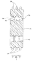
- Figure 9 shows the seal 21 including cavities 30 with interior ribs 38 that seal the wire and ribs 40 that seal the retention pins 24.
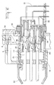
- the exterior ribs 29 that fit inside a hood 8 of the rear housing and are deflected to provide a rear seal, note Figures 6 and 7 to see the position of the seal relative to retaining pins 24 and contacts 18 as terminated to wires 17.
- the cavity 30 includes a sealing diaphragm 39 at one end that is ruptured to fit tightly around the wire 17 once the contact is pushed through the seal.
- the retention pins 24 hold the two housing parts 19, 20 together, and are sealed by the ribs 40 ( Figure 9).
- the plug 4 may be seen in a preassembled condition such that the various covers and housings are held together with the cavities in alignment to receive a contact 18 inserted therethrough.
- the pawl 33 resides half way within the two-step slot 27 and that the retention steps 26 are engaged with a rear edge surface of the slot portion 27a.
- contacts may be inserted as shown in Figure 4, through the aperture 23, by using the polarized feature 23a, and into the position shown in Figure 7. If the contacts are not fully seated within the front housing, the ends of the retention lances 36 will be held outwardly, resting against the forward portions of contact 18 to stub against the rear face of the front cover and preclude a final assembly of the plug.
- the contact retention lances 36 will be in the position shown in Figure 6 with the forward surfaces extending radially into the contact against a rear surface thereof to preclude back out and in such position, allow the forward cover to be axially displaced relative to the central housing from the position shown in Figure 7 to the position shown in Figure 8, at which time the retention step 26 will engage an interior locking tooth 34 proximate the two-step slot 27.
- the plug With the plug assembled in the condition of engagement shown in Figure 8, the plug can now be inserted into a receptacle to reside as indicated in Figure 6.
- Figure 6 also shows the use of a boot 34 that serves to protect the wires 17 and the rear part of the plug.
- the boot 34 includes a forward lip that engages a slot 32a extending around the rear of the rear cover.
- the rear cover includes a recess 32b that allows an optional addition of potting material to pot the wires 17 and the rear of the connector to provide for applications wherein the entire module and connector assembly must be immersed under water for some period of time.
- the invention contemplates uses wherein the seals discussed are adequate for all intended uses and applications wherein the seals need to be assisted by potting, and as shown in Figure 7, the addition of an additional seal 13a that seals the self-tapping screw 13b located in the mounting ear 12 of the receptacle.
- the various cover and housings of plug and receptacle can be molded of engineering plastic having suitable mechanical strength and dielectric qualities with the seals and gaskets made of suitable resilient materials. It should be apparent from the foregoing description that the invention includes several aspects relating to sealing and to assuring a proper contact seating. Proper contact seating is particularly important in sealed connectors but has uses apart from such connectors and sealing has uses apart from proper contact seating structures.
Landscapes
- Connector Housings Or Holding Contact Members (AREA)
Description
Claims (13)
- An electrical connector (4) comprising a housing (20) of insulative material having at least one cavity (22a) therethrough for the receipt of an electrical terminal (18), having a wire (17) trailing therefrom, the connector (4) further comprising a seal member (21) for sealing an interior of said housing (20) by forming a seal with the trailing wire (17), wherein said seal (21) is interfacially disposed against a rear face of said housing (20) and held there; characterized in that said seal (21) has a peripheral outer edge larger than an outer periphery of said housing (20), said peripheral outer edge being for forming a peripheral seal with a hood (3) of a mating connector.
- A connector as claimed in claim 1, characterized in that said seal (21) has a plurality of ribs (29) along said outer peripheral edge for sealing contact against an inner surface of a mating connector.
- A connector as claimed in claim 1 or 2, further characterized by a rear cover member (19) which is placed against said seal (21).
- A connector as claimed in claim 1, 2 or 3, characterized in that the rear cover (19) includes a hood portion (31) which is spaced from and surrounds said peripheral edge of said seal (21).
- A connector as claimed in claim 1, 2, 3 or 4 characterized in that said housing (20) has retention pins (24) which project through said seal (21), and into said cover portion (19), retaining said rear cover (19) and front housing portion (20) together.
- A connector as claimed in any one of claims 1 to 5, characterized in that said rear cover (19) has a rear plate portion which is pressed against said seal.
- A connector as claimed in any one of claims 1 to 6, characterized in that said rear cover (19) has apertures (23) therethrough, which are polarized (23a) for the receipt of terminals (18).
- A connector as claimed in any one of claims 1 to 7, characterized in that the seal (21) has cavities (39) that include a series of ribs (38) for sealing with said wires (17).
- A connector as claimed in any one of claims 1 to 8, characterized in that the seal (21) includes a thin rupturable diaphragm (39) penetrated by the electrical terminal (18) upon insertion.
- A connector as claimed in any one of claims 1 to 9, characterized in that means (36) are operable to preclude mating of the connector with the mating connector unless the terminals are properly seated in the housing (20).
- A connector as claimed in claim 10, characterized in that the connector further includes a front cover (16) telescopically receivable upon the housing (20) to define the terminal receiving cavities (23) wherein resilient means (36) are provided on the housing (20) that are adapted to be driven transversely relative to the cavity by a partially inserted terminal (18) and allowed to move inwardly upon proper seating of the terminal (18) such that telescopic closure of the housing (20) and the forward cover (16) is responsive to a proper terminal seating.
- A connector as claimed in claim 11, characterized in that means (27,33) are included for holding the housing (20) and the front cover (16) in a first position relatively displaced apart prior to seating of said terminals (18) and a second position relatively axially displaced together upon proper seating of said terminals (18).
- A connector as claimed in claim 12, characterized in that resilient retention arms (36) extend from the central housing (20) to preclude movement of said housing (20) and said cover (16) relatively together prior to a proper seating of said terminals (18).
Applications Claiming Priority (2)
| Application Number | Priority Date | Filing Date | Title |
|---|---|---|---|
| ITMI922304 | 1992-10-06 | ||
| ITMI922304A IT1255846B (en) | 1992-10-06 | 1992-10-06 | ELECTRONIC CONNECTOR SEALED |
Publications (3)
| Publication Number | Publication Date |
|---|---|
| EP0592102A2 EP0592102A2 (en) | 1994-04-13 |
| EP0592102A3 EP0592102A3 (en) | 1995-03-22 |
| EP0592102B1 true EP0592102B1 (en) | 1998-07-22 |
Family
ID=11364066
Family Applications (1)
| Application Number | Title | Priority Date | Filing Date |
|---|---|---|---|
| EP93306963A Expired - Lifetime EP0592102B1 (en) | 1992-10-06 | 1993-09-02 | Sealed electrical connector |
Country Status (3)
| Country | Link |
|---|---|
| EP (1) | EP0592102B1 (en) |
| DE (1) | DE69319822T2 (en) |
| IT (1) | IT1255846B (en) |
Families Citing this family (12)
| Publication number | Priority date | Publication date | Assignee | Title |
|---|---|---|---|---|
| JP2813620B2 (en) * | 1993-08-06 | 1998-10-22 | 矢崎総業株式会社 | Waterproof connector |
| JP2573399Y2 (en) * | 1993-10-05 | 1998-05-28 | 矢崎総業株式会社 | Super multi-pole connector |
| ES1029509Y (en) * | 1994-11-23 | 1995-11-01 | Mecanismos Aux Ind | PERFECTED WATERTIGHT CONNECTOR. |
| DE59608044D1 (en) * | 1995-08-01 | 2001-12-06 | Tyco Electronics Logistics Ag | Connectors |
| DE19638368A1 (en) * | 1996-06-20 | 1998-04-02 | Siemens Ag | Motor vehicle central seat plug with protective collar |
| DE19624646C2 (en) * | 1996-06-20 | 1998-07-09 | Siemens Ag | Connectors |
| EP0831559A3 (en) * | 1996-09-19 | 1999-06-16 | Siemens Aktiengesellschaft | Plug connector |
| JPH11195448A (en) * | 1997-12-26 | 1999-07-21 | Amp Japan Ltd | Waterproof-type electric connector |
| DE102018113980A1 (en) | 2018-06-12 | 2019-12-12 | Te Connectivity Germany Gmbh | Method for producing an electrical connector, in particular electrical connector for a high-density header system; and electrical connectors, in particular electrical connectors for the automotive sector; and a high-density header system |
| US10553963B1 (en) * | 2018-09-19 | 2020-02-04 | Te Connectivity Corporation | Insulation crimp with lead-in projection |
| CN112615283A (en) * | 2020-12-14 | 2021-04-06 | 福州市闽工电力设备有限公司 | Energy-saving distribution box safe to use |
| CN115579664A (en) * | 2022-10-31 | 2023-01-06 | 中航光电科技股份有限公司 | A kind of electric connector and its installation method |
Family Cites Families (3)
| Publication number | Priority date | Publication date | Assignee | Title |
|---|---|---|---|---|
| US4544220A (en) * | 1983-12-28 | 1985-10-01 | Amp Incorporated | Connector having means for positively seating contacts |
| US4776813A (en) * | 1987-12-08 | 1988-10-11 | Molex Incorporated | Sealed connector assembly |
| GB8827756D0 (en) * | 1988-11-28 | 1988-12-29 | Amp Great Britain | Electrical connector housing assembly |
-
1992
- 1992-10-06 IT ITMI922304A patent/IT1255846B/en active IP Right Grant
-
1993
- 1993-09-02 EP EP93306963A patent/EP0592102B1/en not_active Expired - Lifetime
- 1993-09-02 DE DE69319822T patent/DE69319822T2/en not_active Expired - Fee Related
Also Published As
| Publication number | Publication date |
|---|---|
| DE69319822T2 (en) | 1998-12-10 |
| ITMI922304A1 (en) | 1994-04-06 |
| ITMI922304A0 (en) | 1992-10-06 |
| EP0592102A2 (en) | 1994-04-13 |
| IT1255846B (en) | 1995-11-17 |
| EP0592102A3 (en) | 1995-03-22 |
| DE69319822D1 (en) | 1998-08-27 |
Similar Documents
| Publication | Publication Date | Title |
|---|---|---|
| US6910905B2 (en) | Waterproof connector | |
| KR101463132B1 (en) | Connector for flat cables | |
| US5240433A (en) | Waterproof electric connector | |
| JP2725753B2 (en) | Sealing member for waterproof connector | |
| JP3097367B2 (en) | Waterproof shield connector | |
| US5890922A (en) | Electrical connector | |
| KR100227170B1 (en) | Electrical connectors with terminal positioning device and guide means for mating connectors | |
| US6059594A (en) | Sealed electrical connector | |
| EP0948101B1 (en) | Electrical connector for making contact with at least one flat foil conductor | |
| CN213401658U (en) | Plug-in connector and sealing element for a plug-in connector | |
| KR101546318B1 (en) | Connector for Connecting Device and the Method for Manufacturing the Connector | |
| JPH08339861A (en) | Connector socket | |
| US7311546B2 (en) | Connector, a mating connector and a connector device | |
| JP2000058187A (en) | Electrical connector | |
| EP0592102A2 (en) | Sealed electrical connector | |
| CA2209701C (en) | Sealed fuse connector | |
| US6638090B2 (en) | Waterproof connector used for a flexible flat cable | |
| EP0125786A2 (en) | Electrical connector assembly | |
| US6132250A (en) | Connector with sealing members | |
| JPH05129046A (en) | Connector structure for flexible wiring board | |
| JP2805436B2 (en) | Simple waterproof connector | |
| EP0654860B1 (en) | Waterproofing assembly for connector | |
| JP3437063B2 (en) | Waterproof connector | |
| JPH08185920A (en) | Electrical connecting structure for circuit board | |
| US6132256A (en) | Design of a lambda module with mating plug |
Legal Events
| Date | Code | Title | Description |
|---|---|---|---|
| PUAI | Public reference made under article 153(3) epc to a published international application that has entered the european phase |
Free format text: ORIGINAL CODE: 0009012 |
|
| AK | Designated contracting states |
Kind code of ref document: A2 Designated state(s): DE FR GB IT |
|
| PUAL | Search report despatched |
Free format text: ORIGINAL CODE: 0009013 |
|
| AK | Designated contracting states |
Kind code of ref document: A3 Designated state(s): DE FR GB IT |
|
| 17P | Request for examination filed |
Effective date: 19950415 |
|
| 17Q | First examination report despatched |
Effective date: 19960523 |
|
| GRAG | Despatch of communication of intention to grant |
Free format text: ORIGINAL CODE: EPIDOS AGRA |
|
| GRAG | Despatch of communication of intention to grant |
Free format text: ORIGINAL CODE: EPIDOS AGRA |
|
| GRAG | Despatch of communication of intention to grant |
Free format text: ORIGINAL CODE: EPIDOS AGRA |
|
| GRAH | Despatch of communication of intention to grant a patent |
Free format text: ORIGINAL CODE: EPIDOS IGRA |
|
| GRAH | Despatch of communication of intention to grant a patent |
Free format text: ORIGINAL CODE: EPIDOS IGRA |
|
| GRAA | (expected) grant |
Free format text: ORIGINAL CODE: 0009210 |
|
| AK | Designated contracting states |
Kind code of ref document: B1 Designated state(s): DE FR GB IT |
|
| ITF | It: translation for a ep patent filed | ||
| REF | Corresponds to: |
Ref document number: 69319822 Country of ref document: DE Date of ref document: 19980827 |
|
| ET | Fr: translation filed | ||
| PLBE | No opposition filed within time limit |
Free format text: ORIGINAL CODE: 0009261 |
|
| STAA | Information on the status of an ep patent application or granted ep patent |
Free format text: STATUS: NO OPPOSITION FILED WITHIN TIME LIMIT |
|
| 26N | No opposition filed | ||
| REG | Reference to a national code |
Ref country code: GB Ref legal event code: IF02 |
|
| PGFP | Annual fee paid to national office [announced via postgrant information from national office to epo] |
Ref country code: GB Payment date: 20040812 Year of fee payment: 12 |
|
| PGFP | Annual fee paid to national office [announced via postgrant information from national office to epo] |
Ref country code: FR Payment date: 20040902 Year of fee payment: 12 |
|
| PG25 | Lapsed in a contracting state [announced via postgrant information from national office to epo] |
Ref country code: GB Free format text: LAPSE BECAUSE OF NON-PAYMENT OF DUE FEES Effective date: 20050902 |
|
| PGFP | Annual fee paid to national office [announced via postgrant information from national office to epo] |
Ref country code: DE Payment date: 20051031 Year of fee payment: 13 |
|
| GBPC | Gb: european patent ceased through non-payment of renewal fee |
Effective date: 20050902 |
|
| PG25 | Lapsed in a contracting state [announced via postgrant information from national office to epo] |
Ref country code: FR Free format text: LAPSE BECAUSE OF NON-PAYMENT OF DUE FEES Effective date: 20060531 |
|
| REG | Reference to a national code |
Ref country code: FR Ref legal event code: ST Effective date: 20060531 |
|
| PG25 | Lapsed in a contracting state [announced via postgrant information from national office to epo] |
Ref country code: DE Free format text: LAPSE BECAUSE OF NON-PAYMENT OF DUE FEES Effective date: 20070403 |
|
| PGFP | Annual fee paid to national office [announced via postgrant information from national office to epo] |
Ref country code: IT Payment date: 20120924 Year of fee payment: 20 |