EP0591453B1 - Multitube ozone generator and method of making same - Google Patents
Multitube ozone generator and method of making same Download PDFInfo
- Publication number
- EP0591453B1 EP0591453B1 EP92915374A EP92915374A EP0591453B1 EP 0591453 B1 EP0591453 B1 EP 0591453B1 EP 92915374 A EP92915374 A EP 92915374A EP 92915374 A EP92915374 A EP 92915374A EP 0591453 B1 EP0591453 B1 EP 0591453B1
- Authority
- EP
- European Patent Office
- Prior art keywords
- tubes
- ozone generator
- ozone
- tube
- hexagonal shaped
- Prior art date
- Legal status (The legal status is an assumption and is not a legal conclusion. Google has not performed a legal analysis and makes no representation as to the accuracy of the status listed.)
- Expired - Lifetime
Links
Images
Classifications
-
- C—CHEMISTRY; METALLURGY
- C01—INORGANIC CHEMISTRY
- C01B—NON-METALLIC ELEMENTS; COMPOUNDS THEREOF; METALLOIDS OR COMPOUNDS THEREOF NOT COVERED BY SUBCLASS C01C
- C01B13/00—Oxygen; Ozone; Oxides or hydroxides in general
- C01B13/10—Preparation of ozone
- C01B13/11—Preparation of ozone by electric discharge
-
- C—CHEMISTRY; METALLURGY
- C01—INORGANIC CHEMISTRY
- C01B—NON-METALLIC ELEMENTS; COMPOUNDS THEREOF; METALLOIDS OR COMPOUNDS THEREOF NOT COVERED BY SUBCLASS C01C
- C01B2201/00—Preparation of ozone by electrical discharge
- C01B2201/10—Dischargers used for production of ozone
- C01B2201/14—Concentric/tubular dischargers
-
- C—CHEMISTRY; METALLURGY
- C01—INORGANIC CHEMISTRY
- C01B—NON-METALLIC ELEMENTS; COMPOUNDS THEREOF; METALLOIDS OR COMPOUNDS THEREOF NOT COVERED BY SUBCLASS C01C
- C01B2201/00—Preparation of ozone by electrical discharge
- C01B2201/20—Electrodes used for obtaining electrical discharge
- C01B2201/22—Constructional details of the electrodes
-
- C—CHEMISTRY; METALLURGY
- C01—INORGANIC CHEMISTRY
- C01B—NON-METALLIC ELEMENTS; COMPOUNDS THEREOF; METALLOIDS OR COMPOUNDS THEREOF NOT COVERED BY SUBCLASS C01C
- C01B2201/00—Preparation of ozone by electrical discharge
- C01B2201/30—Dielectrics used in the electrical dischargers
-
- C—CHEMISTRY; METALLURGY
- C01—INORGANIC CHEMISTRY
- C01B—NON-METALLIC ELEMENTS; COMPOUNDS THEREOF; METALLOIDS OR COMPOUNDS THEREOF NOT COVERED BY SUBCLASS C01C
- C01B2201/00—Preparation of ozone by electrical discharge
- C01B2201/70—Cooling of the discharger; Means for making cooling unnecessary
Definitions
- the present invention relates generally to an ozone generator and method of making the same, and more particularly, to a multi-tube ozone generator having a tube construction in which the plurality of ozone generating tubes are nested together.
- the present invention also relates to a method of making the ozone generator by forming the ozone generating tubes and joining the same together in a compact, nested structure.
- Ozone is a powerfully oxidizing allotropic form of oxygen. Because of its high oxidizing properties, it is commonly used, among other things, as a bacteriacide and virus deactivant and is rapidly attaining preeminence in the treatment of air and of drinking and other water supplies. Ozone is also gaining popularity for use in sewage treatment and any other application where the high oxidizing properties of ozone can be utilized. Ozone does not exist at usable levels naturally, nor is it practically containerized or stored; thus it must be generated commercially, and generally at the location where it is used.
- the principal method used to generate ozone commercially is to pass gaseous oxygen or air through a high voltage, alternating current electric discharge commonly referred to as a silent arc or corona discharge. During this process, molecular oxygen (O 2 ) disassociates into atomic oxygen in an energizing environment that allows the recombination of atoms into the O 3 (ozone) form.
- Such generators generally comprise a pair of electrodes separated by a gap, a dielectric material inserted in the gap, gaseous oxygen or air in the gap, and sufficient voltage potential between the electrodes to cause current to flow through the dielectric and the gaseous oxygen or air.
- the electrodes can be flat, tubular or any configuration which allows opposing electrode surfaces to be parallel.
- Tubular electrodes are commonly employed in multi-tube generators comprising a plurality of tubes generally arranged in a linear or packed configuration.
- a plurality of individual ozone generating tubes are supported by a tube sheet or end plate which contains a plurality of openings to accommodate the ends of the tubes.
- the ends of the plurality of tubes are positioned in the openings of the end plate and secured thereto by swedging. With such a structure, it is necessary for a certain minimum distance to exist between the holes in the end plate to provide sufficient strength to support the tubes.
- the end plate will not be sufficiently strong to support the swedging of adjacent tubes without loosening other joints. Accordingly, the extent to which the plurality of tubes in such a structure can be packed or nested relative to one another is limited.
- multi-tube ozone generator described in US-A-5,009,858, a plurality of tubes are packed into a housing in which the intermediate spaces between the tubes are filled with a thermally conductive material.
- Another multi-tube ozone generator is illustrated in US-A-4,960,570, and similarly in US-A-4,908,189, where the plurality of tubes are arranged linearly between a pair of spaced metal plates.
- a multi-tube ozone generator with the features included in the first part of claim 1 is known from GB-A-492,647.
- the ozone generating tubes are hexagonal shaped, and abut each other, throughout their lengths.
- US-A-1,995,768 describes a tubular heat exchange structure in which a plurality of cylindrical tubes with enlarge hexagonal end portions are assembled in an outer cylindrical shell.
- the structure of the ozone generator of the present invention eliminates the tube sheet or end plate which is common in many prior art ozone generators for supporting the plurality of the tubes. Instead, the ends of the tubes are flared or expanded into a hexagonal shaped configuration for connection to the flared or expanded ends of adjacent tubes by welding or other connection means. Such a structure enables the tubes to be nested together, thereby resulting in a more efficient packing of the tubes and a reduction of overall size of the generator, while still maintaining sufficient spacing between the central portions of individual tubes to facilitate the passage of a cooling fluid. The extent of spacing between the central portions of the tubes is controlled by the extent to which the end portions of the tubes are flared.
- the preferred method of the present invention includes flaring or enlarging the ends of each of the plurality of tubes into a hexagonal configuration and joining the flared hexagonal ends along their corresponding mating edges to form a compact, nested configuration of the ozone generator.
- Such a structure profiles structurally strong and compact and nested arrangement of the individual tubes while also providing sufficient support for the tubes and sufficient spacing between the tubes for the passage of cooling fluids.
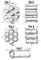
- Figure 1 is an end, elevational view of a prior art ozone generator configuration with the ozone generating elements eliminated for purpose of darity.
- Figure 2 is a sectional side view of the prior art ozone generator of Figure 1 as viewed along the section line 2-2 of Figure 1.
- Figure 3 is an end, elevational view of the ozone generator configuration of the present invention with the ozone generating elements eliminated for purposes of clarity.
- Figure 4 is a sectional side view of the ozone generator of the present invention as viewed along the section line 4-4 of Figure 3.
- Figure 5 is a perspective, fragmentary view showing a flared end of an individual ozone generating tube configuration in accordance with the present invention.
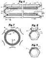
- Figure 6 is a sectional side view of an individual ozone generating tube in accordance with the present invention showing the ozone generating elements within the tube.
- Figure 7 is a sectional, end view of the ozone generating tube of Figure 5 as viewed along the section line 7-7 of Figure 5.
- Figure 8 is an enlarged end view of a portion of the tube structure showing connection between adjacent tubes.
- Figure 9 is an end view showing an alternate configuration for an ozone generating tube.
- the prior art ozone generator illustrated in Figures 1 and 2 indudes a plurality of elongated cylindrical metal tubes 10 which are supported at their ends by tube sheet or end plate 11.
- the end plates 11 comprise a generally circular piece of metal having a plurality of holes to accommodate the ends of the tubes 10.
- the ends of the tubes 10 are forced into the openings of the end plate 11 or are otherwise connected thereto by swedging or the like.
- FIG. 3 is a view similar to that of Figure 1, but which illustrates the plurality of ozone generating tubes 14 configured in accordance with the present invention.
- the ozone generator of the present invention includes a plurality of tubes 14 joined together in a nested configuration.
- Each of the individual tubes 14 includes a generally elongated tubular central portion 16 and a flared or enlarged end portion 17.
- each end of the plurality of tubes 14 is flared or enlarged into a hexagonal configuration 17 so that the mating edges 15 of the hexagonal configuration 17 can be connected to adjacent tubes in a configuration such as that illustrated in Figures 3 and 4.
- the preferred configuration of the central portion 16 of the tubes is that of a circular cross-sectional configuration. This is the most practical configuration for maintaining a constant gap size between the pair of electrodes, although it is contemplated that other configurations can possibly be employed as well.
- the tubes 14 are formed from a conductive material and preferably a metallic material such as stainless steel.
- the thickness of the tubes 14 of the present invention is about 1.7 mm (about 0.065 inches).
- the mating edges 15 of the flared hexagonal ends 17 of each tube are joined with the mating edge 15 of an adjacent tube in the manner illustrated in Figures 3 and 8.
- this connection is a connection by welding or the like, although it is contemplated that other possible means induding rolling, crimping, bonding, etc. may also be considered.
- the area between the central portions 16 of adjacent tubes 14 define cooling passages 18 for a cooling fluid.
- connection between mating edges 15 of the hexagonal ends is sufficient to form a seal for such passages while the concept of the present invention can be used to make multi-tube generators having any number of individual tubes
- the most compact configurations are multi-tube generators having 7,19, 37, 61, 91 or more tubes.
- the most compact configurations are those which have additional tubes equal to the difference between the two most compact configurations having the next greatest number of tubes, plus six.
- a further requirement of the present invention is that the cross-sectional area of the flared or enlarged ends 17 be greater than the cross-sectional area of the central portion 16 of the tubes. This facilitates the formation of the cooling fluid passages 18 between the central portions 16 of adjacent tubes 14.
- FIGS 6 and 7 are sectional side and end views of a single tube in accordance with the present invention illustrating the details of the ozone generating elements.
- the interior of each of the tubes 14 is provided with a dielectric 19 in the form of a dosed end glass or ceramic tube 19, an inner electrode 20 in the form of a metallic foil, a centering mechanism 21 for centering the dielectrictube 19 and a high voltage lead 22.
- the tubular members 14, and in particular the central portions 16, form one of the electrodes in the ozone generating system, while the conductive foil electrode 20 forms the other.
- the tube 14 serves as the grounded electrode which is connected with a ground 24, while the foil electrode 20 within the dielectric 19 is connected by an appropriate lead 22 to a high voltage source 23.
- the foil electrode 20 is in dose proximity to the inner surface of the dielectric 19 so as to be in relatively constant spaced relationship with the central portion 16 of the tube. This defines a gap 25 of constant size between the electrodes 16 and 20.
- a dielectric centering device 21 is provided between the outer surface of the dielectric tube 19 and the inner surface of the tube 14 to maintain a consistent space or gap 25 between such surfaces, and thereby insure relatively constant spacing between the electrodes 16 and 20.
- Spacing devices 21 are common in the art and conventionally include a spacing spring or other member which insures consistent spacing while also permitting free flow of gas through the gap 25. It is contemplated, however, that the centering mechanism 21 could be constructed of a molded plastic material.
- the centering device should be nonmetallic so as not to interfere with the voltage potential between the electrodes 16 and 20. However, if it is metallic, it should be sufficiently spaced from the high voltage electrode 20 so as to predude arcing or other interference.
- the preferred embodiment contemplates the central portion 16 of each tube to have a generally circular cross-sectional configuration; however, it is possible to employ other cross-sectional configurations as well.
- Figure 9 shows a tubular construction with a central portion 16 having a generally hexagonal configuration.
- the dielectric 19 as well as the inner, high voltage electrode 20 it is desirable for the dielectric 19 as well as the inner, high voltage electrode 20 to have a hexagonal configuration so as to maintain a relatively constant gap between the two electrodes.
- the central portion 16 of the tubes can be of circular or various other configurations provided the cross-sectional area of the central portions 16 is smaller than the cross-sectional area of the flared end 17. This assures the existence of cooling fluid passages between the central portions of adjacent tubes.
- ozone generators Although not specifically illustrated, but common structure in prior art ozone generators and known in the art is a chamber or manifold on each end of the generator for the purpose of introducing air or molecular oxygen into one end of the generator and recovering ozone at the other. It is also contemplated that the generator of the present invention would indude means well known in the ozone generator art for supplying a cooling fluid such as water, glycol or the like through the cooling passages 18.
- a cooling fluid such as water, glycol or the like
- ozone generator of the present invention The operation of the ozone generator of the present invention is illustrated best with reference to Figures 6 and 7.
- molecular oxygen or air is provided at one end of the tubular configuration and caused to flow through the gap 25 between the electrodes 20 and 16 from one end of the generator to the other.
- the oxygen or oxygen in the air is subjected to the high voltage potential between the electrodes 20 and 16.
- This causes molecular oxygen to be converted to ozone (03) in a manner known in the art.
- the flow rate of oxygen or air through the system in order to achieve optimum conversion is also known in the art.
- the method of the present invention includes enlarging or flaring each end of a plurality of tubes into a hexagonal configuration and then connecting the mating edges of the flared ends of adjacent tubes to one another to form a compact, nested structure.
- this connection is preferably a connection such as welding or the like in which the mating edges form a seal to define the cooling passages 18.
- the flared ends are formed by inserting a plug having a hexagonal outer configuration and forcing the same into the generally cylindrical tube, thereby causing the ends to be flared into the hexagonal configuration. It is contemplated, however, that other means for flaring the ends could be utilized as well. Further, the preferred embodiment shows both tube ends flared; however, there may be applications in which only one end is flared.
Landscapes
- Chemical & Material Sciences (AREA)
- Organic Chemistry (AREA)
- Inorganic Chemistry (AREA)
- Oxygen, Ozone, And Oxides In General (AREA)
- Treatment Of Water By Oxidation Or Reduction (AREA)
Abstract
Description
- The present invention relates generally to an ozone generator and method of making the same, and more particularly, to a multi-tube ozone generator having a tube construction in which the plurality of ozone generating tubes are nested together. The present invention also relates to a method of making the ozone generator by forming the ozone generating tubes and joining the same together in a compact, nested structure.
- Ozone (O3) is a powerfully oxidizing allotropic form of oxygen. Because of its high oxidizing properties, it is commonly used, among other things, as a bacteriacide and virus deactivant and is rapidly attaining preeminence in the treatment of air and of drinking and other water supplies. Ozone is also gaining popularity for use in sewage treatment and any other application where the high oxidizing properties of ozone can be utilized. Ozone does not exist at usable levels naturally, nor is it practically containerized or stored; thus it must be generated commercially, and generally at the location where it is used. The principal method used to generate ozone commercially is to pass gaseous oxygen or air through a high voltage, alternating current electric discharge commonly referred to as a silent arc or corona discharge. During this process, molecular oxygen (O2) disassociates into atomic oxygen in an energizing environment that allows the recombination of atoms into the O3 (ozone) form.
- Various ozone generators employing silent arc discharge conditions currently exist in the art. Such generators generally comprise a pair of electrodes separated by a gap, a dielectric material inserted in the gap, gaseous oxygen or air in the gap, and sufficient voltage potential between the electrodes to cause current to flow through the dielectric and the gaseous oxygen or air. The electrodes can be flat, tubular or any configuration which allows opposing electrode surfaces to be parallel. Tubular electrodes are commonly employed in multi-tube generators comprising a plurality of tubes generally arranged in a linear or packed configuration. Although it is desirable to pack the plurality of tubes in a multi-tube generator as close as possible while still allowing sufficient space between the tubes for cooling purposes, the compactability of currently existing multi-tube ozone generators has been limited by the manner in which such generators are constructed. In one typical prior art ozone generator, a plurality of individual ozone generating tubes are supported by a tube sheet or end plate which contains a plurality of openings to accommodate the ends of the tubes. During construction, the ends of the plurality of tubes are positioned in the openings of the end plate and secured thereto by swedging. With such a structure, it is necessary for a certain minimum distance to exist between the holes in the end plate to provide sufficient strength to support the tubes. If the openings to which the tubes are joined are too close together, the end plate will not be sufficiently strong to support the swedging of adjacent tubes without loosening other joints. Accordingly, the extent to which the plurality of tubes in such a structure can be packed or nested relative to one another is limited.
- In a further multi-tube ozone generator described in US-A-5,009,858, a plurality of tubes are packed into a housing in which the intermediate spaces between the tubes are filled with a thermally conductive material. Another multi-tube ozone generator is illustrated in US-A-4,960,570, and similarly in US-A-4,908,189, where the plurality of tubes are arranged linearly between a pair of spaced metal plates.
- A multi-tube ozone generator with the features included in the first part of claim 1 is known from GB-A-492,647. In this arrangement, the ozone generating tubes are hexagonal shaped, and abut each other, throughout their lengths.
- US-A-1,995,768 describes a tubular heat exchange structure in which a plurality of cylindrical tubes with enlarge hexagonal end portions are assembled in an outer cylindrical shell.
- It is an object of the present invention to provide a multi-tube ozone generator which facilitates maximum nesting of the tubes relative to one another, while still maintaining sufficient cooling passages therebetween.
- This object is accomplished by the arrangement defined in claim 1.
- The structure of the ozone generator of the present invention eliminates the tube sheet or end plate which is common in many prior art ozone generators for supporting the plurality of the tubes. Instead, the ends of the tubes are flared or expanded into a hexagonal shaped configuration for connection to the flared or expanded ends of adjacent tubes by welding or other connection means. Such a structure enables the tubes to be nested together, thereby resulting in a more efficient packing of the tubes and a reduction of overall size of the generator, while still maintaining sufficient spacing between the central portions of individual tubes to facilitate the passage of a cooling fluid. The extent of spacing between the central portions of the tubes is controlled by the extent to which the end portions of the tubes are flared.
- The preferred method of the present invention includes flaring or enlarging the ends of each of the plurality of tubes into a hexagonal configuration and joining the flared hexagonal ends along their corresponding mating edges to form a compact, nested configuration of the ozone generator.
Such a structure profiles structurally strong and compact and nested arrangement of the individual tubes while also providing sufficient support for the tubes and sufficient spacing between the tubes for the passage of cooling fluids. - The present invention will become apparent with reference to the drawings, the description of the preferred embodiment and method and the appended claims.
- Figure 1 is an end, elevational view of a prior art ozone generator configuration with the ozone generating elements eliminated for purpose of darity.
- Figure 2 is a sectional side view of the prior art ozone generator of Figure 1 as viewed along the section line 2-2 of Figure 1.
- Figure 3 is an end, elevational view of the ozone generator configuration of the present invention with the ozone generating elements eliminated for purposes of clarity.
- Figure 4 is a sectional side view of the ozone generator of the present invention as viewed along the section line 4-4 of Figure 3.
- Figure 5 is a perspective, fragmentary view showing a flared end of an individual ozone generating tube configuration in accordance with the present invention.
- Figure 6 is a sectional side view of an individual ozone generating tube in accordance with the present invention showing the ozone generating elements within the tube.
- Figure 7 is a sectional, end view of the ozone generating tube of Figure 5 as viewed along the section line 7-7 of Figure 5.
- Figure 8 is an enlarged end view of a portion of the tube structure showing connection between adjacent tubes.
- Figure 9 is an end view showing an alternate configuration for an ozone generating tube.
- The understanding and description of the preferred embodiment and method of the present invention disclosed in Figures 3 - 8 is assisted by first describing and understanding the prior art structure illustrated in Figures 1 and 2.
- The prior art ozone generator illustrated in Figures 1 and 2 indudes a plurality of elongated
cylindrical metal tubes 10 which are supported at their ends by tube sheet or end plate 11. In many prior art structures, the end plates 11 comprise a generally circular piece of metal having a plurality of holes to accommodate the ends of thetubes 10. During construction, the ends of thetubes 10 are forced into the openings of the end plate 11 or are otherwise connected thereto by swedging or the like. With this structure, it is necessary for a certainminimum distance 12 to exist between the holes in the tube sheet to provide sufficient strength to allow the connection technique and for supporting thetubes 10. If the openings are too dose together, the end plate 11 will not be sufficiently strong to support thetubes 10. Accordingly, in the prior art structure of Figures 1 and 2, a certainminimum distance 12 is needed between the various tubes. This requireddistance 12 necessarily limits the extent to which thetubes 10 can be packed or nested relative to one another. - The general structure of the ozone generator of the present invention is best understood with reference to Figures 3, 4 and 5. Figure 3 is a view similar to that of Figure 1, but which illustrates the plurality of
ozone generating tubes 14 configured in accordance with the present invention. The ozone generator of the present invention includes a plurality oftubes 14 joined together in a nested configuration. Each of theindividual tubes 14 includes a generally elongated tubularcentral portion 16 and a flared or enlargedend portion 17. In the preferred embodiment, each end of the plurality oftubes 14 is flared or enlarged into ahexagonal configuration 17 so that themating edges 15 of thehexagonal configuration 17 can be connected to adjacent tubes in a configuration such as that illustrated in Figures 3 and 4. - For the reasons described in greater detail below, the preferred configuration of the
central portion 16 of the tubes is that of a circular cross-sectional configuration. This is the most practical configuration for maintaining a constant gap size between the pair of electrodes, although it is contemplated that other configurations can possibly be employed as well. Further, thetubes 14 are formed from a conductive material and preferably a metallic material such as stainless steel. The thickness of thetubes 14 of the present invention is about 1.7 mm (about 0.065 inches). - In the preferred embodiment, the mating edges 15 of the flared hexagonal ends 17 of each tube are joined with the
mating edge 15 of an adjacent tube in the manner illustrated in Figures 3 and 8. Preferably, this connection is a connection by welding or the like, although it is contemplated that other possible means induding rolling, crimping, bonding, etc. may also be considered. The area between thecentral portions 16 ofadjacent tubes 14 definecooling passages 18 for a cooling fluid. Thus, it is preferable for the connection between mating edges 15 of the hexagonal ends to be sufficient to form a seal for such passages while the concept of the present invention can be used to make multi-tube generators having any number of individual tubes, the most compact configurations are multi-tube generators having 7,19, 37, 61, 91 or more tubes. For generators with the number of tubes being greater than 91, the most compact configurations are those which have additional tubes equal to the difference between the two most compact configurations having the next greatest number of tubes, plus six. - A further requirement of the present invention is that the cross-sectional area of the flared or enlarged ends 17 be greater than the cross-sectional area of the
central portion 16 of the tubes. This facilitates the formation of the coolingfluid passages 18 between thecentral portions 16 ofadjacent tubes 14. - Figures 6 and 7 are sectional side and end views of a single tube in accordance with the present invention illustrating the details of the ozone generating elements. As illustrated in the structure of Figures 6 and 7, the interior of each of the
tubes 14 is provided with a dielectric 19 in the form of a dosed end glass orceramic tube 19, aninner electrode 20 in the form of a metallic foil, a centeringmechanism 21 for centering thedielectrictube 19 and ahigh voltage lead 22. - In the ozone generator of the present invention, the
tubular members 14, and in particular thecentral portions 16, form one of the electrodes in the ozone generating system, while theconductive foil electrode 20 forms the other. In the preferred embodiment, thetube 14 serves as the grounded electrode which is connected with aground 24, while thefoil electrode 20 within the dielectric 19 is connected by anappropriate lead 22 to ahigh voltage source 23. Preferably, thefoil electrode 20 is in dose proximity to the inner surface of the dielectric 19 so as to be in relatively constant spaced relationship with thecentral portion 16 of the tube. This defines agap 25 of constant size between theelectrodes device 21 is provided between the outer surface of thedielectric tube 19 and the inner surface of thetube 14 to maintain a consistent space orgap 25 between such surfaces, and thereby insure relatively constant spacing between theelectrodes devices 21 are common in the art and conventionally include a spacing spring or other member which insures consistent spacing while also permitting free flow of gas through thegap 25. It is contemplated, however, that the centeringmechanism 21 could be constructed of a molded plastic material. Preferably, the centering device should be nonmetallic so as not to interfere with the voltage potential between theelectrodes high voltage electrode 20 so as to predude arcing or other interference. - As indicated above, the preferred embodiment contemplates the
central portion 16 of each tube to have a generally circular cross-sectional configuration; however, it is possible to employ other cross-sectional configurations as well. For example, Figure 9 shows a tubular construction with acentral portion 16 having a generally hexagonal configuration. With this structure, it is desirable for the dielectric 19 as well as the inner,high voltage electrode 20 to have a hexagonal configuration so as to maintain a relatively constant gap between the two electrodes. Thus, although it is required for the flared ends to have a generally hexagonal configuration, thecentral portion 16 of the tubes can be of circular or various other configurations provided the cross-sectional area of thecentral portions 16 is smaller than the cross-sectional area of the flaredend 17. This assures the existence of cooling fluid passages between the central portions of adjacent tubes. - Although not specifically illustrated, but common structure in prior art ozone generators and known in the art is a chamber or manifold on each end of the generator for the purpose of introducing air or molecular oxygen into one end of the generator and recovering ozone at the other. It is also contemplated that the generator of the present invention would indude means well known in the ozone generator art for supplying a cooling fluid such as water, glycol or the like through the
cooling passages 18. - The operation of the ozone generator of the present invention is illustrated best with reference to Figures 6 and 7. During such operation, molecular oxygen or air is provided at one end of the tubular configuration and caused to flow through the
gap 25 between theelectrodes gap 25, the oxygen or oxygen in the air is subjected to the high voltage potential between theelectrodes - The method of the present invention includes enlarging or flaring each end of a plurality of tubes into a hexagonal configuration and then connecting the mating edges of the flared ends of adjacent tubes to one another to form a compact, nested structure. As indicated above, this connection is preferably a connection such as welding or the like in which the mating edges form a seal to define the
cooling passages 18. In the preferred method, the flared ends are formed by inserting a plug having a hexagonal outer configuration and forcing the same into the generally cylindrical tube, thereby causing the ends to be flared into the hexagonal configuration. It is contemplated, however, that other means for flaring the ends could be utilized as well. Further, the preferred embodiment shows both tube ends flared; however, there may be applications in which only one end is flared.
Claims (17)
- A multi-tube ozone generator comprising a plurality of ozone generating tubes (14) joined to one another, each tube including a central tubular portion (16) and a hexagonal shaped end (17),
characterised inthat the end (17) has a greater cross-sectional area than the central portion (16),that the tubes (14) are joined along edges defined by the hexagonal shaped ends (17), andthat the central tubular portions (16) of adjacent tubes are spaced from one another to define a cooling fluid passage (18) between adjacent tubes. - The ozone generator of claim 1 wherein said hexagonal end defines a plurality of mating edges and wherein said tubes are joined to one another along their corresponding mating edges.
- The ozone generator of claim 1 wherein said central tubular portion is elongated.
- The ozone generator of claim 1 wherein said central tubular portion has a generally circular cross-sectional configuration.
- The ozone generator of claim 1 wherein each of said tubes includes a weld joint along corresponding edges of said hexagonal shaped ends of adjacent tubes.
- The ozone generator of claim 1 wherein each of said tubes is constructed of a conductive material.
- The ozone generator of claim 1 wherein each tube includes ozone generating means.
- The ozone generator of claim 7 wherein each of said tubes is constructed of a conducting material forming a first electrode and wherein said ozone generating means includes a dielectric member and a second electrode, said second electrode being positioned within said dielectric member and spaced from said first electrode.
- The ozone generator of claim 8 wherein said ozone generating means indudes a centering means for centering said dielectric member within said central tubular portion.
- The ozone generator of claim 9 including means for connecting one of said first and second electrodes to a high voltage source.
- The ozone generator of claim 1 wherein the number of ozone generating tubes is equal to 7,19, 37, 61 or 91.
- The ozone generator of claim 1 wherein each end of said tubes includes an enlarged hexagonal shaped end.
- The ozone generator of claim 1 wherein each of said tubes is parallel to one another.
- A method of making a multi-tube ozone generator comprising the steps of:forming an enlarged, hexagonal shaped end in each of a plurality of ozone generating tubes; andconnecting aajacent tubes to one another along corresponding edges defined by said hexagonal shaped ends.
- The method of claim 14 including connecting adjacent tubes to one another by welding.
- The method of claim 14 including forming an enlarged hexagonal shaped end at each end of said plurality of ozone generating tubes.
- The method of claim 14 wherein said hexagonal shaped end is formed by inserting a hexagonal shaped plug into said tube.
Applications Claiming Priority (3)
| Application Number | Priority Date | Filing Date | Title |
|---|---|---|---|
| US07/721,280 US5258165A (en) | 1991-06-26 | 1991-06-26 | Multi-tube ozone generator and method of making same |
| US721280 | 1991-06-26 | ||
| PCT/US1992/005499 WO1993000161A1 (en) | 1991-06-26 | 1992-06-26 | Multitube ozone generator and method of making same |
Publications (3)
| Publication Number | Publication Date |
|---|---|
| EP0591453A1 EP0591453A1 (en) | 1994-04-13 |
| EP0591453A4 EP0591453A4 (en) | 1994-07-20 |
| EP0591453B1 true EP0591453B1 (en) | 1996-09-11 |
Family
ID=24897301
Family Applications (1)
| Application Number | Title | Priority Date | Filing Date |
|---|---|---|---|
| EP92915374A Expired - Lifetime EP0591453B1 (en) | 1991-06-26 | 1992-06-26 | Multitube ozone generator and method of making same |
Country Status (9)
| Country | Link |
|---|---|
| US (1) | US5258165A (en) |
| EP (1) | EP0591453B1 (en) |
| CN (1) | CN1070163A (en) |
| AT (1) | ATE142601T1 (en) |
| AU (1) | AU2306992A (en) |
| CA (1) | CA2112253A1 (en) |
| DE (1) | DE69213740T2 (en) |
| MX (1) | MX9203434A (en) |
| WO (1) | WO1993000161A1 (en) |
Families Citing this family (18)
| Publication number | Priority date | Publication date | Assignee | Title |
|---|---|---|---|---|
| DE4400517C2 (en) * | 1994-01-07 | 1996-11-07 | Sorbios Verfahrenstech | Device for generating ozone |
| JP4015210B2 (en) * | 1996-05-30 | 2007-11-28 | 富士電機システムズ株式会社 | Ozone generator |
| IL118741A0 (en) * | 1996-06-26 | 1996-10-16 | Ozontech Ltd | Ozone application for disinfection purification and deodorization |
| US5824274A (en) * | 1996-10-16 | 1998-10-20 | Long; Ron | Ozone treatment system for point of use purification of water and sanitizing agent for surfaces, articles and foods |
| US5871701A (en) * | 1997-04-01 | 1999-02-16 | Long; Ron | Ozone generator with small-diameter dielectric tubes |
| US6060027A (en) | 1998-05-14 | 2000-05-09 | Fantom Technologies Inc. | Ozone generator |
| US6376387B2 (en) * | 1999-07-09 | 2002-04-23 | Applied Materials, Inc. | Method of sealing an epitaxial silicon layer on a substrate |
| US6315887B1 (en) | 1999-11-08 | 2001-11-13 | Amir Salama | Device and method for the purification of polluted water |
| US6517731B2 (en) | 2000-06-16 | 2003-02-11 | Fantom Technologies Inc. | Ozonation process |
| EP1488454B1 (en) * | 2001-02-16 | 2013-01-16 | Ignis Innovation Inc. | Pixel driver circuit for an organic light emitting diode |
| CA2443496C (en) * | 2003-09-30 | 2011-10-11 | Dana Canada Corporation | Tube bundle heat exchanger comprising tubes with expanded sections |
| US20050131266A1 (en) * | 2003-10-08 | 2005-06-16 | Clemson University | Carbonaceous waste treatment system and method |
| ES2249978B1 (en) * | 2004-04-07 | 2007-06-16 | Valeo Termico, S.A. | HEAT EXCHANGER FOR GASES, ESPECIALLY OF EXHAUST GASES OF AN ENGINE. |
| CN102897715A (en) * | 2012-10-31 | 2013-01-30 | 苏州金奥臭氧有限公司 | Cooling device for ozone generator |
| FR3049698A1 (en) * | 2016-04-04 | 2017-10-06 | Didier Costes | COLLECTOR OF HONEYCOMB TUBES |
| CN107244657B (en) * | 2017-08-09 | 2023-03-31 | 沈阳东方钛业股份有限公司 | Ozone generator with multi-tube structure and manufacturing method thereof |
| WO2020005772A1 (en) * | 2018-06-25 | 2020-01-02 | Booker Charles Kent | Surface energy enhancing fluid and applications on living tissues |
| JP7738496B2 (en) * | 2022-02-04 | 2025-09-12 | 三菱重工業株式会社 | heat exchanger |
Family Cites Families (17)
| Publication number | Priority date | Publication date | Assignee | Title |
|---|---|---|---|---|
| US1845670A (en) * | 1929-05-18 | 1932-02-16 | Lebrun Paul Francois Joseph | Ozonizer |
| US1840510A (en) * | 1930-03-29 | 1932-01-12 | Winchester Repeating Arms Co | Heat interchanger |
| US1950211A (en) * | 1932-08-31 | 1934-03-06 | Fedders Mfg Co Inc | Oil cooling radiator |
| US1950021A (en) * | 1933-09-05 | 1934-03-06 | Jr Charles L Creech | Extension table |
| US1995768A (en) * | 1934-03-23 | 1935-03-26 | Hugo P Fesenmaier | Tubular heat exchange structure and a surrounding shell therefor |
| GB492647A (en) * | 1937-03-23 | 1938-09-23 | Francis Colin Sutton | Apparatus for the production of ozone |
| US2710835A (en) * | 1952-11-25 | 1955-06-14 | William A Pardey | Ozone making machine |
| US2672948A (en) * | 1952-12-09 | 1954-03-23 | Trion Inc | Ionizing unit for electrostatic filters |
| US2989144A (en) * | 1956-01-02 | 1961-06-20 | Styrie Otto | Method of and apparatus for purifying and decontaminating exhaust gases of combustion devices |
| DE1076897B (en) * | 1958-03-26 | 1960-03-03 | Franz Herberich | Device for generating ozone in ozone generator tubes to improve air |
| US2979158A (en) * | 1958-10-17 | 1961-04-11 | Gordon M Genge & Company Inc | Electrostatic particle separating apparatus |
| US3942020A (en) * | 1974-12-09 | 1976-03-02 | Cubic Corporation | Corona discharge ozone generator |
| CH596092A5 (en) * | 1975-07-25 | 1978-02-28 | Univ Moskovsk | High frequency tubular ozoniser |
| US4585057A (en) * | 1982-09-30 | 1986-04-29 | Krw Energy Systems Inc. | Cooled tubesheet inlet for abrasive fluid heat exchanger |
| US4908189A (en) * | 1988-07-15 | 1990-03-13 | Henkel Corporation | Concentric tube ozonator |
| CH676844A5 (en) * | 1988-09-09 | 1991-03-15 | Asea Brown Boveri | |
| CH677356A5 (en) * | 1989-03-07 | 1991-05-15 | Asea Brown Boveri |
-
1991
- 1991-06-26 US US07/721,280 patent/US5258165A/en not_active Expired - Fee Related
-
1992
- 1992-06-26 DE DE69213740T patent/DE69213740T2/en not_active Expired - Fee Related
- 1992-06-26 CA CA002112253A patent/CA2112253A1/en not_active Abandoned
- 1992-06-26 AT AT92915374T patent/ATE142601T1/en not_active IP Right Cessation
- 1992-06-26 AU AU23069/92A patent/AU2306992A/en not_active Abandoned
- 1992-06-26 MX MX9203434A patent/MX9203434A/en not_active IP Right Cessation
- 1992-06-26 CN CN92105968.XA patent/CN1070163A/en active Pending
- 1992-06-26 WO PCT/US1992/005499 patent/WO1993000161A1/en not_active Ceased
- 1992-06-26 EP EP92915374A patent/EP0591453B1/en not_active Expired - Lifetime
Also Published As
| Publication number | Publication date |
|---|---|
| DE69213740D1 (en) | 1996-10-17 |
| DE69213740T2 (en) | 1997-04-03 |
| MX9203434A (en) | 1993-04-01 |
| CA2112253A1 (en) | 1993-01-07 |
| ATE142601T1 (en) | 1996-09-15 |
| US5258165A (en) | 1993-11-02 |
| EP0591453A4 (en) | 1994-07-20 |
| CN1070163A (en) | 1993-03-24 |
| EP0591453A1 (en) | 1994-04-13 |
| AU2306992A (en) | 1993-01-25 |
| WO1993000161A1 (en) | 1993-01-07 |
Similar Documents
| Publication | Publication Date | Title |
|---|---|---|
| US5258165A (en) | Multi-tube ozone generator and method of making same | |
| JP3803401B2 (en) | Ozone generator | |
| US4504446A (en) | Ozone generator | |
| JP3404405B2 (en) | Equipment for generating ozone | |
| US5354541A (en) | Ozone generator | |
| US5009858A (en) | Device for generating ozone | |
| JPS5866283A (en) | Gaseous or liquidus medium heating device | |
| JP2693186B2 (en) | Ozone generator | |
| TWI241275B (en) | Ozonizer | |
| US6190622B1 (en) | Ozone generator | |
| EP0840081A3 (en) | Heat exchanger and method for manufacturing the same | |
| CA2354068C (en) | Apparatus and method for reducing operating voltage in gas discharge devices | |
| KR102415353B1 (en) | Discharge Tube For Double Ozone Generation | |
| US11735409B2 (en) | Lamp comprising multiple component designs and constructions | |
| US5306471A (en) | Concentric ozonator tube assesmbly | |
| US5254317A (en) | Device for generating ozone | |
| KR102494002B1 (en) | Electrode for Ozone generating apparatus and Discharge tube using the same | |
| RU2108647C1 (en) | Radiation generating unit of multichannel laser | |
| JP3900662B2 (en) | Ozone generator | |
| RU2118939C1 (en) | Small-size ozone generator | |
| JP2000226202A (en) | Tube type ozone generator | |
| US20030194358A1 (en) | Ozone generator | |
| JP2013018682A (en) | Ozone generating apparatus, and method for manufacturing the same | |
| CN214990283U (en) | Ozone generator convenient to assembly | |
| JP2008100897A (en) | Ozone generator |
Legal Events
| Date | Code | Title | Description |
|---|---|---|---|
| PUAI | Public reference made under article 153(3) epc to a published international application that has entered the european phase |
Free format text: ORIGINAL CODE: 0009012 |
|
| 17P | Request for examination filed |
Effective date: 19931222 |
|
| AK | Designated contracting states |
Kind code of ref document: A1 Designated state(s): AT BE CH DE DK ES FR GB GR IT LI LU MC NL SE |
|
| RHK1 | Main classification (correction) |
Ipc: C01B 13/11 |
|
| A4 | Supplementary search report drawn up and despatched |
Effective date: 19940527 |
|
| AK | Designated contracting states |
Kind code of ref document: A4 Designated state(s): AT BE CH DE DK ES FR GB GR IT LI LU MC NL SE |
|
| 17Q | First examination report despatched |
Effective date: 19941202 |
|
| GRAH | Despatch of communication of intention to grant a patent |
Free format text: ORIGINAL CODE: EPIDOS IGRA |
|
| GRAA | (expected) grant |
Free format text: ORIGINAL CODE: 0009210 |
|
| AK | Designated contracting states |
Kind code of ref document: B1 Designated state(s): AT BE CH DE DK ES FR GB GR IT LI LU MC NL SE |
|
| PG25 | Lapsed in a contracting state [announced via postgrant information from national office to epo] |
Ref country code: NL Free format text: LAPSE BECAUSE OF FAILURE TO SUBMIT A TRANSLATION OF THE DESCRIPTION OR TO PAY THE FEE WITHIN THE PRESCRIBED TIME-LIMIT Effective date: 19960911 Ref country code: IT Free format text: LAPSE BECAUSE OF FAILURE TO SUBMIT A TRANSLATION OF THE DESCRIPTION OR TO PAY THE FEE WITHIN THE PRE;WARNING: LAPSES OF ITALIAN PATENTS WITH EFFECTIVE DATE BEFORE 2007 MAY HAVE OCCURRED AT ANY TIME BEFORE 2007. THE CORRECT EFFECTIVE DATE MAY BE DIFFERENT FROM THE ONE RECORDED.SCRIBED TIME-LIMIT Effective date: 19960911 Ref country code: GR Free format text: LAPSE BECAUSE OF FAILURE TO SUBMIT A TRANSLATION OF THE DESCRIPTION OR TO PAY THE FEE WITHIN THE PRESCRIBED TIME-LIMIT Effective date: 19960911 Ref country code: ES Free format text: THE PATENT HAS BEEN ANNULLED BY A DECISION OF A NATIONAL AUTHORITY Effective date: 19960911 Ref country code: DK Effective date: 19960911 Ref country code: BE Effective date: 19960911 Ref country code: AT Effective date: 19960911 |
|
| REF | Corresponds to: |
Ref document number: 142601 Country of ref document: AT Date of ref document: 19960915 Kind code of ref document: T |
|
| REF | Corresponds to: |
Ref document number: 69213740 Country of ref document: DE Date of ref document: 19961017 |
|
| PG25 | Lapsed in a contracting state [announced via postgrant information from national office to epo] |
Ref country code: SE Effective date: 19961211 |
|
| ET | Fr: translation filed | ||
| NLV1 | Nl: lapsed or annulled due to failure to fulfill the requirements of art. 29p and 29m of the patents act | ||
| REG | Reference to a national code |
Ref country code: CH Ref legal event code: NV Representative=s name: TROESCH SCHEIDEGGER WERNER AG |
|
| PG25 | Lapsed in a contracting state [announced via postgrant information from national office to epo] |
Ref country code: LU Free format text: LAPSE BECAUSE OF NON-PAYMENT OF DUE FEES Effective date: 19970630 |
|
| PGFP | Annual fee paid to national office [announced via postgrant information from national office to epo] |
Ref country code: CH Payment date: 19970630 Year of fee payment: 6 |
|
| PLBE | No opposition filed within time limit |
Free format text: ORIGINAL CODE: 0009261 |
|
| STAA | Information on the status of an ep patent application or granted ep patent |
Free format text: STATUS: NO OPPOSITION FILED WITHIN TIME LIMIT |
|
| 26N | No opposition filed | ||
| PG25 | Lapsed in a contracting state [announced via postgrant information from national office to epo] |
Ref country code: MC Effective date: 19971231 |
|
| PGFP | Annual fee paid to national office [announced via postgrant information from national office to epo] |
Ref country code: FR Payment date: 19980609 Year of fee payment: 7 |
|
| PGFP | Annual fee paid to national office [announced via postgrant information from national office to epo] |
Ref country code: GB Payment date: 19980617 Year of fee payment: 7 |
|
| PG25 | Lapsed in a contracting state [announced via postgrant information from national office to epo] |
Ref country code: LI Free format text: LAPSE BECAUSE OF NON-PAYMENT OF DUE FEES Effective date: 19980630 Ref country code: CH Free format text: LAPSE BECAUSE OF NON-PAYMENT OF DUE FEES Effective date: 19980630 |
|
| PGFP | Annual fee paid to national office [announced via postgrant information from national office to epo] |
Ref country code: DE Payment date: 19980706 Year of fee payment: 7 |
|
| REG | Reference to a national code |
Ref country code: CH Ref legal event code: PL |
|
| PG25 | Lapsed in a contracting state [announced via postgrant information from national office to epo] |
Ref country code: GB Free format text: LAPSE BECAUSE OF NON-PAYMENT OF DUE FEES Effective date: 19990626 |
|
| PG25 | Lapsed in a contracting state [announced via postgrant information from national office to epo] |
Ref country code: FR Free format text: THE PATENT HAS BEEN ANNULLED BY A DECISION OF A NATIONAL AUTHORITY Effective date: 19990630 |
|
| GBPC | Gb: european patent ceased through non-payment of renewal fee |
Effective date: 19990626 |
|
| PG25 | Lapsed in a contracting state [announced via postgrant information from national office to epo] |
Ref country code: DE Free format text: LAPSE BECAUSE OF NON-PAYMENT OF DUE FEES Effective date: 20000503 |
|
| REG | Reference to a national code |
Ref country code: FR Ref legal event code: ST |