EP0591425B1 - Flow coat galvanizing - Google Patents
Flow coat galvanizing Download PDFInfo
- Publication number
- EP0591425B1 EP0591425B1 EP92914769A EP92914769A EP0591425B1 EP 0591425 B1 EP0591425 B1 EP 0591425B1 EP 92914769 A EP92914769 A EP 92914769A EP 92914769 A EP92914769 A EP 92914769A EP 0591425 B1 EP0591425 B1 EP 0591425B1
- Authority
- EP
- European Patent Office
- Prior art keywords
- molten zinc
- cross
- zinc
- linear element
- vat
- Prior art date
- Legal status (The legal status is an assumption and is not a legal conclusion. Google has not performed a legal analysis and makes no representation as to the accuracy of the status listed.)
- Expired - Lifetime
Links
- 238000005246 galvanizing Methods 0.000 title claims abstract description 29
- HCHKCACWOHOZIP-UHFFFAOYSA-N Zinc Chemical compound [Zn] HCHKCACWOHOZIP-UHFFFAOYSA-N 0.000 claims abstract description 79
- 229910052725 zinc Inorganic materials 0.000 claims abstract description 79
- 239000011701 zinc Substances 0.000 claims abstract description 79
- 238000000034 method Methods 0.000 claims abstract description 12
- 239000007788 liquid Substances 0.000 claims abstract description 5
- 239000011248 coating agent Substances 0.000 claims abstract description 3
- 238000000576 coating method Methods 0.000 claims abstract description 3
- 230000000630 rising effect Effects 0.000 claims abstract 2
- 230000008569 process Effects 0.000 claims description 7
- 239000007789 gas Substances 0.000 claims description 4
- 239000011261 inert gas Substances 0.000 claims description 3
- 238000010924 continuous production Methods 0.000 claims description 2
- 238000010926 purge Methods 0.000 claims description 2
- 230000005484 gravity Effects 0.000 claims 1
- 238000004519 manufacturing process Methods 0.000 description 11
- 229910052751 metal Inorganic materials 0.000 description 10
- 239000002184 metal Substances 0.000 description 10
- 238000005086 pumping Methods 0.000 description 6
- 230000009467 reduction Effects 0.000 description 5
- 230000003628 erosive effect Effects 0.000 description 4
- 239000003570 air Substances 0.000 description 3
- 238000007654 immersion Methods 0.000 description 3
- 238000012423 maintenance Methods 0.000 description 3
- 238000003466 welding Methods 0.000 description 3
- IJGRMHOSHXDMSA-UHFFFAOYSA-N Atomic nitrogen Chemical compound N#N IJGRMHOSHXDMSA-UHFFFAOYSA-N 0.000 description 2
- 229910000831 Steel Inorganic materials 0.000 description 2
- 230000008901 benefit Effects 0.000 description 2
- 230000015572 biosynthetic process Effects 0.000 description 2
- 238000010438 heat treatment Methods 0.000 description 2
- 230000006872 improvement Effects 0.000 description 2
- 229910001338 liquidmetal Inorganic materials 0.000 description 2
- 238000005554 pickling Methods 0.000 description 2
- 238000002360 preparation method Methods 0.000 description 2
- 230000003134 recirculating effect Effects 0.000 description 2
- 238000009751 slip forming Methods 0.000 description 2
- 239000010959 steel Substances 0.000 description 2
- 229910001335 Galvanized steel Inorganic materials 0.000 description 1
- 241000282887 Suidae Species 0.000 description 1
- 239000002253 acid Substances 0.000 description 1
- 230000009471 action Effects 0.000 description 1
- 239000012080 ambient air Substances 0.000 description 1
- 230000004888 barrier function Effects 0.000 description 1
- 238000001816 cooling Methods 0.000 description 1
- 239000000498 cooling water Substances 0.000 description 1
- 238000005520 cutting process Methods 0.000 description 1
- 230000001419 dependent effect Effects 0.000 description 1
- 230000000694 effects Effects 0.000 description 1
- 238000009429 electrical wiring Methods 0.000 description 1
- 230000008030 elimination Effects 0.000 description 1
- 238000003379 elimination reaction Methods 0.000 description 1
- 238000004880 explosion Methods 0.000 description 1
- 239000012530 fluid Substances 0.000 description 1
- 239000008397 galvanized steel Substances 0.000 description 1
- 239000008187 granular material Substances 0.000 description 1
- 230000006698 induction Effects 0.000 description 1
- 238000009434 installation Methods 0.000 description 1
- 239000000463 material Substances 0.000 description 1
- 238000002844 melting Methods 0.000 description 1
- 230000008018 melting Effects 0.000 description 1
- 239000011490 mineral wool Substances 0.000 description 1
- 230000004048 modification Effects 0.000 description 1
- 238000012986 modification Methods 0.000 description 1
- 230000003472 neutralizing effect Effects 0.000 description 1
- 229910052757 nitrogen Inorganic materials 0.000 description 1
- 238000012856 packing Methods 0.000 description 1
- 230000000737 periodic effect Effects 0.000 description 1
- 239000004576 sand Substances 0.000 description 1
- 238000009991 scouring Methods 0.000 description 1
- 238000012546 transfer Methods 0.000 description 1
- XLYOFNOQVPJJNP-UHFFFAOYSA-N water Substances O XLYOFNOQVPJJNP-UHFFFAOYSA-N 0.000 description 1
Images

Classifications
-
- C—CHEMISTRY; METALLURGY
- C23—COATING METALLIC MATERIAL; COATING MATERIAL WITH METALLIC MATERIAL; CHEMICAL SURFACE TREATMENT; DIFFUSION TREATMENT OF METALLIC MATERIAL; COATING BY VACUUM EVAPORATION, BY SPUTTERING, BY ION IMPLANTATION OR BY CHEMICAL VAPOUR DEPOSITION, IN GENERAL; INHIBITING CORROSION OF METALLIC MATERIAL OR INCRUSTATION IN GENERAL
- C23C—COATING METALLIC MATERIAL; COATING MATERIAL WITH METALLIC MATERIAL; SURFACE TREATMENT OF METALLIC MATERIAL BY DIFFUSION INTO THE SURFACE, BY CHEMICAL CONVERSION OR SUBSTITUTION; COATING BY VACUUM EVAPORATION, BY SPUTTERING, BY ION IMPLANTATION OR BY CHEMICAL VAPOUR DEPOSITION, IN GENERAL
- C23C2/00—Hot-dipping or immersion processes for applying the coating material in the molten state without affecting the shape; Apparatus therefor
- C23C2/34—Hot-dipping or immersion processes for applying the coating material in the molten state without affecting the shape; Apparatus therefor characterised by the shape of the material to be treated
- C23C2/36—Elongated material
- C23C2/38—Wires; Tubes
-
- C—CHEMISTRY; METALLURGY
- C23—COATING METALLIC MATERIAL; COATING MATERIAL WITH METALLIC MATERIAL; CHEMICAL SURFACE TREATMENT; DIFFUSION TREATMENT OF METALLIC MATERIAL; COATING BY VACUUM EVAPORATION, BY SPUTTERING, BY ION IMPLANTATION OR BY CHEMICAL VAPOUR DEPOSITION, IN GENERAL; INHIBITING CORROSION OF METALLIC MATERIAL OR INCRUSTATION IN GENERAL
- C23C—COATING METALLIC MATERIAL; COATING MATERIAL WITH METALLIC MATERIAL; SURFACE TREATMENT OF METALLIC MATERIAL BY DIFFUSION INTO THE SURFACE, BY CHEMICAL CONVERSION OR SUBSTITUTION; COATING BY VACUUM EVAPORATION, BY SPUTTERING, BY ION IMPLANTATION OR BY CHEMICAL VAPOUR DEPOSITION, IN GENERAL
- C23C2/00—Hot-dipping or immersion processes for applying the coating material in the molten state without affecting the shape; Apparatus therefor
- C23C2/003—Apparatus
- C23C2/0034—Details related to elements immersed in bath
-
- C—CHEMISTRY; METALLURGY
- C23—COATING METALLIC MATERIAL; COATING MATERIAL WITH METALLIC MATERIAL; CHEMICAL SURFACE TREATMENT; DIFFUSION TREATMENT OF METALLIC MATERIAL; COATING BY VACUUM EVAPORATION, BY SPUTTERING, BY ION IMPLANTATION OR BY CHEMICAL VAPOUR DEPOSITION, IN GENERAL; INHIBITING CORROSION OF METALLIC MATERIAL OR INCRUSTATION IN GENERAL
- C23C—COATING METALLIC MATERIAL; COATING MATERIAL WITH METALLIC MATERIAL; SURFACE TREATMENT OF METALLIC MATERIAL BY DIFFUSION INTO THE SURFACE, BY CHEMICAL CONVERSION OR SUBSTITUTION; COATING BY VACUUM EVAPORATION, BY SPUTTERING, BY ION IMPLANTATION OR BY CHEMICAL VAPOUR DEPOSITION, IN GENERAL
- C23C2/00—Hot-dipping or immersion processes for applying the coating material in the molten state without affecting the shape; Apparatus therefor
- C23C2/003—Apparatus
- C23C2/0034—Details related to elements immersed in bath
- C23C2/00342—Moving elements, e.g. pumps or mixers
-
- C—CHEMISTRY; METALLURGY
- C23—COATING METALLIC MATERIAL; COATING MATERIAL WITH METALLIC MATERIAL; CHEMICAL SURFACE TREATMENT; DIFFUSION TREATMENT OF METALLIC MATERIAL; COATING BY VACUUM EVAPORATION, BY SPUTTERING, BY ION IMPLANTATION OR BY CHEMICAL VAPOUR DEPOSITION, IN GENERAL; INHIBITING CORROSION OF METALLIC MATERIAL OR INCRUSTATION IN GENERAL
- C23C—COATING METALLIC MATERIAL; COATING MATERIAL WITH METALLIC MATERIAL; SURFACE TREATMENT OF METALLIC MATERIAL BY DIFFUSION INTO THE SURFACE, BY CHEMICAL CONVERSION OR SUBSTITUTION; COATING BY VACUUM EVAPORATION, BY SPUTTERING, BY ION IMPLANTATION OR BY CHEMICAL VAPOUR DEPOSITION, IN GENERAL
- C23C2/00—Hot-dipping or immersion processes for applying the coating material in the molten state without affecting the shape; Apparatus therefor
- C23C2/003—Apparatus
- C23C2/0038—Apparatus characterised by the pre-treatment chambers located immediately upstream of the bath or occurring locally before the dipping process
-
- C—CHEMISTRY; METALLURGY
- C23—COATING METALLIC MATERIAL; COATING MATERIAL WITH METALLIC MATERIAL; CHEMICAL SURFACE TREATMENT; DIFFUSION TREATMENT OF METALLIC MATERIAL; COATING BY VACUUM EVAPORATION, BY SPUTTERING, BY ION IMPLANTATION OR BY CHEMICAL VAPOUR DEPOSITION, IN GENERAL; INHIBITING CORROSION OF METALLIC MATERIAL OR INCRUSTATION IN GENERAL
- C23C—COATING METALLIC MATERIAL; COATING MATERIAL WITH METALLIC MATERIAL; SURFACE TREATMENT OF METALLIC MATERIAL BY DIFFUSION INTO THE SURFACE, BY CHEMICAL CONVERSION OR SUBSTITUTION; COATING BY VACUUM EVAPORATION, BY SPUTTERING, BY ION IMPLANTATION OR BY CHEMICAL VAPOUR DEPOSITION, IN GENERAL
- C23C2/00—Hot-dipping or immersion processes for applying the coating material in the molten state without affecting the shape; Apparatus therefor
- C23C2/006—Pattern or selective deposits
- C23C2/0062—Pattern or selective deposits without pre-treatment of the material to be coated, e.g. using masking elements such as casings, shields, fixtures or blocking elements
-
- Y—GENERAL TAGGING OF NEW TECHNOLOGICAL DEVELOPMENTS; GENERAL TAGGING OF CROSS-SECTIONAL TECHNOLOGIES SPANNING OVER SEVERAL SECTIONS OF THE IPC; TECHNICAL SUBJECTS COVERED BY FORMER USPC CROSS-REFERENCE ART COLLECTIONS [XRACs] AND DIGESTS
- Y10—TECHNICAL SUBJECTS COVERED BY FORMER USPC
- Y10S—TECHNICAL SUBJECTS COVERED BY FORMER USPC CROSS-REFERENCE ART COLLECTIONS [XRACs] AND DIGESTS
- Y10S118/00—Coating apparatus
- Y10S118/12—Pipe and tube immersion
Definitions
- This invention relates to a continuous process for galvanizing linear materials such as wire, rod, tube, or pipe, by immersing the axially moving linear element incrementally in molten zinc.
- the galvanization of the exterior surface of pipe or conduit as part of the continuous manufacture thereof from an endless strip of sheet metal has been practiced commercially for a number of years.
- the process basically consists of roll-forming the metal strip into tubular form after drawing it from an endless supply, welding the seam, scarfing and dressing off the weld, and passing the continuously formed tube through a pickling bath and rinse.
- the tube is then passed through a preheating station and then through a bath of molten zinc, after which the excess zinc is removed, the tube cooled to handling temperature in a water bath, and the tube sheared into finite lengths.
- the continuously-formed, rapidly moving tube after appropriate preparation, was passed through an elongated trough positioned above a pool of molten zinc in a large vat, from which a stream of the liquid metal was pumped to maintain a substantial and overflowing body of molten zinc in the trough as well as to replace the zinc being carried away from the trough as a fluid coating on the tube.
- the amount of zinc pumped from the vat to the upper trough was substantial, and as those skilled in the art will appreciate, the formation of dross at the walls of the vat and the trough, and their consequent erosion due to the scouring action of the recirculating zinc, was likewise substantial.
- the accelerated erosion of the pump impeller and pump housing in this strenuous service required their replacement in days rather than weeks, but was regarded as a necessary maintenance burden to be tolerated as part of the continuous integrated manufacture of galvanized pipe and tube.
- DE-A-2 105 661 and DE-A-2 624 069 show continuous galvanization of wire, rod, tube or other elongated metal articles by passing them through a tube in which a pool of zinc is maintained by end closures having openings which fit the cross-sectional profile of the articles. Zinc is pumped into the tube and overflows from separate overflow pipes which return the molten zinc to the zinc kettle.
- the present invention is based upon the discovery that effective galvanization does not require immersion of the traveling tube or pipe in the molten zinc for the length of time provided by the elongated galvanizing troughs and tubes of the prior art installations.
- Effective galvanization is accomplished by the method and apparatus of the invention by passing the tube or pipe through a flowing fountain of zinc confined by a T-section at the top of the delivery pipe of the pump.
- the traveling tube or pipe is thus surrounded by molten zinc drawn directly from the pool in the vat without transfer to a secondary pool in an immersion-trough positioned above the main pool in the vat.
- the reduction of the circulating amount of zinc permitted by this arrangement has greatly reduced the erosion of the pump parts and extended their useful life by an order of magnitude.
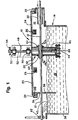
- FIGURE 1 shows galvanizing station 10 in an overall system for the continuous manufacture of galvanized pipe or conduit 12. While the method and apparatus illustrated were developed in the stated context, the invention is believed applicable to the continuous galvanization of other linear metal product such as wire or rod.
- the conduit 12 passes through the galvanizing station from right to left as viewed in FIGURE 1, delivered in rapid axial motion from a roll-forming station where an endless band of metal is progressively rolled into tubular form with abutting edges which are closed by an electrically welded seam which is scarfed and dressed en route to the galvanizing station.
- the conduit In preparation for galvanizing, which in essentially total immersion of the conduit 12 in molten zinc, the conduit is first cleaned by a pickling bath of acid, followed by a neutralizing rinse, after which the tube is preheated immediately before entry into the galvanizing station. Preheating is conveniently accomplished by passing the conduit axially through an induction heating coil.
- these pregalvanizing steps are well understood in the art, they are not here shown, reference simply being made to the Krengel patent, No. 3,259,148, in which one such system is illustrated and described.
- the galvanizing station 10 is essentially an elongated vat 14 of molten zinc constructed in generally rectangular form of welded steel plate and formed to provide a space is above the predetermined level of the pool 18 of liquid zinc therein, maintained in molten condition at about 450° C. (850° F.), i.e., about 55° C. (100° F.) above the melting point of zinc.
- the heating means may be gas or oil burners directed against the bottom of the vat.
- the space 16 above the pool of liquid zinc is closed by a series of covers 20, 22, and 24 having downwardly extending perimeter flanges 26 which are received in troughs 28 extending around the periphery of the vat and transversely of the vat, as well, to permit the use of multiple covers for convenient access to the interior of the vat for maintenance purposes.
- the troughs 28 in which the cover flanges are received are partially filled with a granular material, such as sand, which forms a barrier to the escape of the inert gas with which the space 16 above the molten zinc is filled and maintained slightly above atmospheric pressure to prevent, or at least limit, the entry of air into that space.
- the conduit 12 enters the galvanizing station from the right immediately from the preheater, the housing for which is normally abutted against the entering end of the galvanizing station with an intervening packing of mineral wool or the like to limit the entrainment of ambient air into the galvanizing zone above the molten metal.
- the conduit enters the station 10 through a hole in the vat wall and thence through a larger tube 30 intended to bring the conduit into more intimate contact with the inert purging gas.
- the tube then passes through the galvanizing apparatus 32 of the invention and exits the galvanizing zone through an aligned hole 34 in the far wall 36 of the space.
- the far wall 36 of the space is positioned above and extends downwardly into the pool 18 of molten zinc at some distance removed from the end wall 38 of the vat proper, providing a small area 40 of open access to the pool of zinc through which the inventory of molten zinc is maintained by the periodic addition of pigs of the metal.
- That open area also serves the further purpose of receiving the molten zinc trimmed from the outer surface of the conduit 12 by an air knife 42 which consists of a series of nozzles in an annular manifold directed to deliver a cutting stream of compressed air onto the surface of the conduit to trim the excess zinc therefrom, propelling the same in a flat trajectory onto the exposed area 40 of the pool of molten zinc.
- the workpiece conduit 12 travels at a good rate of speed, not infrequently in excess of 182 meters (600 feet) per minute.
- the galvanizing apparatus 32 per se is shown mounted on the central vat cover 22. It comprises essentially a submersible centrifugal pump 44 secured as by welding to the lower end of a thick-walled mounting pipe 46 welded to the underside of the vat cover. Supporting structure 48 mounted on the upper side of the cover 22 provides two bearings 50 for the vertical shaft 52 of the pump, which is driven at its upper end from a variable speed, vertical electric motor 54 by a V-belt entrained on a pair of speed-reducing pulleys 56 and 58.
- a double-sided pump impeller (not shown) which when rotating draws the molten zinc from the pool through a central intake in the bottom plate of the pump and a similar central hole in the top plate of the pump, through which the shaft 52 passes with wide clearance to admit the zinc to the upper impeller blades.
- Access by the liquid zinc to the upper central opening is provided by ports in the supporting structure between the upper plate of the pump and the mounting pipe 46.
- the mounting pipe 46 completely shrouds the pump shaft from the inert gas in the space 16, eliminating the need for shaft seals between the shaft 52 and cover 22 to prevent the escape of the gas.
- the pump delivers the molten zinc to a riser pipe 60 which carries the liquid metal upwardly to a T-head 62 in the form of an open tube aligned to receive the rapidly moving conduit 12 axially therethrough.
- a pair of brackets 64 welded to the mounting pipe 46 of the pump, encircle the T-head 62 in a split-block configuration in which the two parts of each bracket are secured together by screws to maintain the T-head firmly in position.
- variable speed pump 44 is driven at a speed adequate to deliver a constant upward flow of molten zinc sufficient to surround the conduit traveling through the T-head 62, which, in contrast with the trough type of galvanizing apparatus heretofore employed, may be relatively short, i.e., of the order of 50.8 cm (20 inches), with the excess zinc spilling from the ends of the T-head to fall directly into the pool from which it was pumped, it being noted that the surface of the pool 18 beneath the confined, nitrogen-filled space is free from the frothy oxide layer at the uncovered left-hand end of the vat.
- FIGURES 1 and 2 employs to advantage the submersible centrifugal pump 44
- the invention in its broader aspects is not dependent upon a specific form of pump.
- Other kinds of pumps for example, non-contact electromagnetic pumps, may also be employed, although preferably with suitable provision for the variable delivery rate achieved by speed control of the mechanical pump illustrated.
- the cross-head of the T has an inside diameter of 73 mm (2-7/8 inches), and has been used successfully in the illustrated setup to galvanize pipe up to 56 mm (2.197 inches) in outside diameter, i.e., nominal 50.8 mm (two-inch) thin wall U.S. electrical conduit, and down to 18 mm (0.706 inch) O.D., i.e., nominal 12.7 mm (half-inch) U.S. thin wall conduit for electrical wiring.
- the invention has made possible a significant reduction in the amount of scrap generated on start-up, with concomitant improvement in manufacturing safety, and reduced the time required to switch the line from galvanized to non-galvanized manufacture.
- scrap generation each time the roll-stands of the roll-forming station are changed to set the line up to make a different size of pipe or conduit, adjustments at the roll-forming, and sometimes the welding, stations are usually required before an acceptable seam-closing weld is achieved. Only then is it safe to begin galvanizing, for to pass a zinc-filled, open-seam tube into the cooling bath at the temperature and heat energy levels involved is to invite explosion by flash-vaporizing the cooling water.
- the short lift of the molten zinc from the pool 18 to the cross-head 62 at the top or the riser pipe 60 results in the almost instantaneous production of quality product with little or no scrap of galvanized conduit incident to start-up.
- the rapid emptying as well as refilling of the riser pipe 60 and cross-head 62 moreover, has reduced changeover of the line from galvanized to non-galvanized manufacture, and vice versa, to simply turning the pump motor off or on, and, either way, results in almost negligible scrap with substantially instantaneous changeover.
- the riser pipe 60' merges off center with the open-ended tubular cross-head of the T-head 62', so that the in-flowing stream of molten zinc enters the cross-head tangentially to wrap the through-passing conduit 12' with the tangentially flowing stream of zinc.
- the greater overflow of zinc occurs at the exiting end of the cross-head, and when that overflow is at its greatest, i.e., at the higher pumping rates employed for smaller size workpiece conduit, the overflow stream may project a substantial distance from the end of the cross-head, in the absence of provision for reducing the velocity of the overflowing zinc.
- Such provision can conveniently be made, as shown in FIGURE 7, by belling out the ends of the cross-head 62" to increase the cross-sectional area of the cross-head to reduce the velocity, and shorten the trajectory of the streams from the ends of the cross-head.
Landscapes
- Chemical & Material Sciences (AREA)
- Chemical Kinetics & Catalysis (AREA)
- Engineering & Computer Science (AREA)
- Materials Engineering (AREA)
- Mechanical Engineering (AREA)
- Metallurgy (AREA)
- Organic Chemistry (AREA)
- Coating With Molten Metal (AREA)
- Fuel Cell (AREA)
Abstract
Description
- This invention relates to a continuous process for galvanizing linear materials such as wire, rod, tube, or pipe, by immersing the axially moving linear element incrementally in molten zinc.
- The galvanization of the exterior surface of pipe or conduit as part of the continuous manufacture thereof from an endless strip of sheet metal has been practiced commercially for a number of years. The process basically consists of roll-forming the metal strip into tubular form after drawing it from an endless supply, welding the seam, scarfing and dressing off the weld, and passing the continuously formed tube through a pickling bath and rinse. The tube is then passed through a preheating station and then through a bath of molten zinc, after which the excess zinc is removed, the tube cooled to handling temperature in a water bath, and the tube sheared into finite lengths.
- Such an integrated continuous manufacturing process is disclosed, for example, in U.S. Patent 3,226,817, with particular emphasis on the galvanization step of the process in U.S. Patents 3,226,817, 3,259,148 and 3,877,975.
- In the galvanizing stations of such prior integrated processes, the continuously-formed, rapidly moving tube, after appropriate preparation, was passed through an elongated trough positioned above a pool of molten zinc in a large vat, from which a stream of the liquid metal was pumped to maintain a substantial and overflowing body of molten zinc in the trough as well as to replace the zinc being carried away from the trough as a fluid coating on the tube.
- The amount of zinc pumped from the vat to the upper trough was substantial, and as those skilled in the art will appreciate, the formation of dross at the walls of the vat and the trough, and their consequent erosion due to the scouring action of the recirculating zinc, was likewise substantial. The accelerated erosion of the pump impeller and pump housing in this strenuous service required their replacement in days rather than weeks, but was regarded as a necessary maintenance burden to be tolerated as part of the continuous integrated manufacture of galvanized pipe and tube.
- DE-A-2 105 661 and DE-A-2 624 069 show continuous galvanization of wire, rod, tube or other elongated metal articles by passing them through a tube in which a pool of zinc is maintained by end closures having openings which fit the cross-sectional profile of the articles. Zinc is pumped into the tube and overflows from separate overflow pipes which return the molten zinc to the zinc kettle.
- The present invention is based upon the discovery that effective galvanization does not require immersion of the traveling tube or pipe in the molten zinc for the length of time provided by the elongated galvanizing troughs and tubes of the prior art installations. Effective galvanization is accomplished by the method and apparatus of the invention by passing the tube or pipe through a flowing fountain of zinc confined by a T-section at the top of the delivery pipe of the pump. The traveling tube or pipe is thus surrounded by molten zinc drawn directly from the pool in the vat without transfer to a secondary pool in an immersion-trough positioned above the main pool in the vat. The reduction of the circulating amount of zinc permitted by this arrangement has greatly reduced the erosion of the pump parts and extended their useful life by an order of magnitude.
- The invention is described in reference to the accompanying drawings, in which:
- FIGURE 1 is a diagrammatic, sectioned elevational view of galvanizing station in accordance with the invention, as installed in an integrated line for the continuous manufacture of galvanized steel tube or pipe;
- FIGURE 2 is a diagrammatic end view of the submersible pump and galvanizing apparatus, lifted from the surrounding walls of the zinc vat;
- FIGURES 3 and 4 are enlarged end views of the T-head of the galvanizing apparatus, atop the riser pipe from the pump, showing the relationship of the flow-confining T-head to different diameters of tube or pipe passing through the T-head; and
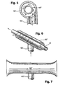
- FIGURE 5 is an enlarged end view of a T-head modified for tangential introduction of the stream of molten zinc;
- FIGURE 6 is an oblique projection of the T-head of FIGURE 5, partly sectioned to expose the interior thereof and indicating diagrammatically the flow path of at least a portion of the molten zinc under operating conditions; and
- FIGURE 7 is an elevational view of a further modification of the T-head of FIGURE 1 or FIGURE 6 with belled ends.
- Referring to FIGURES 1 and 2 for a general description of the method and apparatus of the invention, FIGURE 1 shows galvanizing
station 10 in an overall system for the continuous manufacture of galvanized pipe orconduit 12. While the method and apparatus illustrated were developed in the stated context, the invention is believed applicable to the continuous galvanization of other linear metal product such as wire or rod. - The
conduit 12 passes through the galvanizing station from right to left as viewed in FIGURE 1, delivered in rapid axial motion from a roll-forming station where an endless band of metal is progressively rolled into tubular form with abutting edges which are closed by an electrically welded seam which is scarfed and dressed en route to the galvanizing station. In preparation for galvanizing, which in essentially total immersion of theconduit 12 in molten zinc, the conduit is first cleaned by a pickling bath of acid, followed by a neutralizing rinse, after which the tube is preheated immediately before entry into the galvanizing station. Preheating is conveniently accomplished by passing the conduit axially through an induction heating coil. As these pregalvanizing steps are well understood in the art, they are not here shown, reference simply being made to the Krengel patent, No. 3,259,148, in which one such system is illustrated and described. - The galvanizing
station 10 is essentially anelongated vat 14 of molten zinc constructed in generally rectangular form of welded steel plate and formed to provide a space is above the predetermined level of the pool 18 of liquid zinc therein, maintained in molten condition at about 450° C. (850° F.), i.e., about 55° C. (100° F.) above the melting point of zinc. The heating means, not shown, may be gas or oil burners directed against the bottom of the vat. - The
space 16 above the pool of liquid zinc is closed by a series ofcovers perimeter flanges 26 which are received introughs 28 extending around the periphery of the vat and transversely of the vat, as well, to permit the use of multiple covers for convenient access to the interior of the vat for maintenance purposes. Thetroughs 28 in which the cover flanges are received are partially filled with a granular material, such as sand, which forms a barrier to the escape of the inert gas with which thespace 16 above the molten zinc is filled and maintained slightly above atmospheric pressure to prevent, or at least limit, the entry of air into that space. - As earlier noted, the
conduit 12 enters the galvanizing station from the right immediately from the preheater, the housing for which is normally abutted against the entering end of the galvanizing station with an intervening packing of mineral wool or the like to limit the entrainment of ambient air into the galvanizing zone above the molten metal. The conduit enters thestation 10 through a hole in the vat wall and thence through alarger tube 30 intended to bring the conduit into more intimate contact with the inert purging gas. The tube then passes through the galvanizingapparatus 32 of the invention and exits the galvanizing zone through an alignedhole 34 in thefar wall 36 of the space. - It will be noted that the
far wall 36 of the space is positioned above and extends downwardly into the pool 18 of molten zinc at some distance removed from theend wall 38 of the vat proper, providing asmall area 40 of open access to the pool of zinc through which the inventory of molten zinc is maintained by the periodic addition of pigs of the metal. That open area also serves the further purpose of receiving the molten zinc trimmed from the outer surface of theconduit 12 by anair knife 42 which consists of a series of nozzles in an annular manifold directed to deliver a cutting stream of compressed air onto the surface of the conduit to trim the excess zinc therefrom, propelling the same in a flat trajectory onto the exposedarea 40 of the pool of molten zinc. - In such a manufacturing line, the workpiece conduit 12 travels at a good rate of speed, not infrequently in excess of 182 meters (600 feet) per minute.
- The galvanizing
apparatus 32 per se is shown mounted on thecentral vat cover 22. It comprises essentially a submersiblecentrifugal pump 44 secured as by welding to the lower end of a thick-walledmounting pipe 46 welded to the underside of the vat cover. Supportingstructure 48 mounted on the upper side of thecover 22 provides twobearings 50 for thevertical shaft 52 of the pump, which is driven at its upper end from a variable speed, verticalelectric motor 54 by a V-belt entrained on a pair of speed-reducingpulleys shaft 52 passes with wide clearance to admit the zinc to the upper impeller blades. Access by the liquid zinc to the upper central opening is provided by ports in the supporting structure between the upper plate of the pump and themounting pipe 46. Themounting pipe 46 completely shrouds the pump shaft from the inert gas in thespace 16, eliminating the need for shaft seals between theshaft 52 and cover 22 to prevent the escape of the gas. - The pump delivers the molten zinc to a
riser pipe 60 which carries the liquid metal upwardly to a T-head 62 in the form of an open tube aligned to receive the rapidly movingconduit 12 axially therethrough. To support the T-head firmly, a pair ofbrackets 64, welded to themounting pipe 46 of the pump, encircle the T-head 62 in a split-block configuration in which the two parts of each bracket are secured together by screws to maintain the T-head firmly in position. - The
variable speed pump 44 is driven at a speed adequate to deliver a constant upward flow of molten zinc sufficient to surround the conduit traveling through the T-head 62, which, in contrast with the trough type of galvanizing apparatus heretofore employed, may be relatively short, i.e., of the order of 50.8 cm (20 inches), with the excess zinc spilling from the ends of the T-head to fall directly into the pool from which it was pumped, it being noted that the surface of the pool 18 beneath the confined, nitrogen-filled space is free from the frothy oxide layer at the uncovered left-hand end of the vat. - While the invention as specifically illustrated in FIGURES 1 and 2 employs to advantage the submersible
centrifugal pump 44, the invention in its broader aspects is not dependent upon a specific form of pump. Other kinds of pumps, for example, non-contact electromagnetic pumps, may also be employed, although preferably with suitable provision for the variable delivery rate achieved by speed control of the mechanical pump illustrated. - In one apparatus of the illustrated kind, the cross-head of the T has an inside diameter of 73 mm (2-7/8 inches), and has been used successfully in the illustrated setup to galvanize pipe up to 56 mm (2.197 inches) in outside diameter, i.e., nominal 50.8 mm (two-inch) thin wall U.S. electrical conduit, and down to 18 mm (0.706 inch) O.D., i.e., nominal 12.7 mm (half-inch) U.S. thin wall conduit for electrical wiring. As will be apparent from FIGURES 3 and 4, different sizes of tube, pipe, or conduit to be galvanized require the pumping of varying amounts of zinc to completely immerse the traveling workpiece on its passage through the T-head, a larger amount of zinc being required for smaller tube in a cross-head of given size, particularly as it is preferred to pump the zinc at a rate sufficient to flood the annular space between the traveling workpiece and the surrounding T-head for at least a portion of the length of the T-Head. The pumping requirements, however, are much reduced from those of the prior art galvanizing apparatus such as illustrated by Krengel Patent No. 3,259,148, because the pumping of zinc in quantity sufficient to maintain the molten metal in a separate sizable trough above the pool of zinc is not required by the illustrated apparatus, the pressure head to which the zinc must be pumped is reduced, and the galvanizing process may be carried on with less recirculation of the molten metal.
- These differences result in very significant benefits.
- First, a very noticeable reduction in the erosion of the pumps has been experienced. Whereas pump life had heretofore ranged from one to three days depending upon severity of service, the reduced pumping requirements of the present invention have increased pump life to in excess of thirty days, an order of magnitude improvement.
- Secondly, elimination of the upper immersion trough, and the reduction of the recirculating currents in the molten metal at the lower pumping requirements of the apparatus of the invention, have resulted in a noticeable reduction of the formation of dross, and consequent longer life for the steel walls of the zinc vat. Moreover, while not yet realized in existing zinc vats, it is apparent that without the necessity for maintaining an elongated upper galvanizing trough separate from the main body of molten zinc in the vat, the vat itself can be downsized by approximately one-half, which will effect further economies of maintenance to the zinc vat and at the same time reduce the amount of energy required to maintain the constant inventory of molten zinc.
- Lastly, the invention has made possible a significant reduction in the amount of scrap generated on start-up, with concomitant improvement in manufacturing safety, and reduced the time required to switch the line from galvanized to non-galvanized manufacture. As to scrap generation, each time the roll-stands of the roll-forming station are changed to set the line up to make a different size of pipe or conduit, adjustments at the roll-forming, and sometimes the welding, stations are usually required before an acceptable seam-closing weld is achieved. Only then is it safe to begin galvanizing, for to pass a zinc-filled, open-seam tube into the cooling bath at the temperature and heat energy levels involved is to invite explosion by flash-vaporizing the cooling water.
- To avoid this danger, the line must be run until an acceptable seam is produced before galvanizing may proceed. In the upper trough and lower vat combination, a not insignificant further amount of time was required to bring the zinc in the upper trough up to the overflow level to produce acceptable product. This in turn resulted in the production of scrap even after an acceptably welded seam was produced.
- In the apparatus of the invention, the short lift of the molten zinc from the pool 18 to the cross-head 62 at the top or the
riser pipe 60 results in the almost instantaneous production of quality product with little or no scrap of galvanized conduit incident to start-up. The rapid emptying as well as refilling of theriser pipe 60 andcross-head 62, moreover, has reduced changeover of the line from galvanized to non-galvanized manufacture, and vice versa, to simply turning the pump motor off or on, and, either way, results in almost negligible scrap with substantially instantaneous changeover. - In the modified form of the galvanizing apparatus of this invention shown in FIGURE 5, the riser pipe 60' merges off center with the open-ended tubular cross-head of the T-head 62', so that the in-flowing stream of molten zinc enters the cross-head tangentially to wrap the through-passing conduit 12' with the tangentially flowing stream of zinc.
- Given that the conduit 12' is itself passing axially through the cross-head 62' at speeds of up to 182.9 m/min (600 feet per minute), the adherence of the zinc to the rapidly moving workpiece applies a force to the molten zinc in the direction of the workpiece flow, from right to left in FIGURE 6, resulting in the helical wrap of workpiece by the flowing zinc. This flow pattern is illustrated in oversimplified and diagrammatic form in FIGURE 6. Actually, because the tubular cross-head 62' is open at both ends without restriction, other than the through-passing workpiece conduit 12' itself, there is some back flow of molten zinc to the entering end of the cross-head, from which the molten zinc falls to the surface of the pool in the vat.
- The greater overflow of zinc occurs at the exiting end of the cross-head, and when that overflow is at its greatest, i.e., at the higher pumping rates employed for smaller size workpiece conduit, the overflow stream may project a substantial distance from the end of the cross-head, in the absence of provision for reducing the velocity of the overflowing zinc. Such provision can conveniently be made, as shown in FIGURE 7, by belling out the ends of the cross-head 62" to increase the cross-sectional area of the cross-head to reduce the velocity, and shorten the trajectory of the streams from the ends of the cross-head.
- The features of the invention believed new and patentable are set forth in the accompanying claims.
Claims (10)
- A continuous process for galvanizing linear elements, including a method of applying molten zinc to the cleansed and preheated linear element to be galvanized comprising:passing the linear element axially through an open tube having open ends of cross-sectional area at least as great as any other cross-section of said tube;supplying molten zinc to said open tube from a pool of molten zinc beneath said open tube at a rate sufficient to immerse the linear element in flowing molten zinc as it passes through said open tube; andcollecting by gravity the excess zinc flowing from the ends of said open tube and dripping from the coated linear element.
- The process of Claim 1 wherein the molten zinc is pumped to the underside of said open tube intermediate its ends at a rate sufficient to flood the annular space between said linear element and said open tube for at least a portion of the length of said open tube.
- The process of Claim 1 wherein the molten zinc is introduced into said open tube transversely and eccentrically thereof.
- The process of Claim 3 wherein the open tube has a circular cross-section, the molten zinc is introduced tangentially thereof and is drawn into a helical flow pattern by the frictional drag of the through-passing linear element.
- An apparatus for the continuous galvanization of a linear element such as pipe, tube, rod, or wire, having a galvanizing station including a vat for holding a pool of molten zinc and maintaining said pool in a pumpable liquid state, a cover for the vat to maintain a substantially closed space above the pool of molten zinc, means for introducing an inert gas continually into said space to purge the space of atmospheric air, and ingress and egress openings in the walls defining said space for the passage through said space of said linear element to be coated with molten zinc;an applicator for coating said linear element comprising:a conduit having an open end beneath the surface of the pool of molten zinc and extending above the surface of the pool, and terminating in an open-ended tubular cross-tee, said cross-tee being in axial alignment with said ingress and egress openings so as to encircle said linear element traveling through said space;said conduit having associated therewith a pump for delivering molten zinc continuously to said cross-tee at a rate adequate to immerse said linear element in molten zinc while passing through said cross-tee.
- The apparatus of Claim 5 wherein said pump is a submersible centrifugal pump suspended from the vat cover and said conduit includes a delivery pipe rising from the pump body to said cross-tee.
- The apparatus of Claim 6 wherein the body of the submersible pump is suspended from the vat cover by a rigid thick-walled mounting pipe welded to the underside of the cover, the pump impeller is driven by a shaft extending upwardly through the pipe to bearings mounted on structure secured on the top side of the vat cover, the enclosure of the drive shaft within said mounting pipe seals the passage of the drive shaft through the vat cover against the escape of gas from said space, and said motor is mounted on said structure atop the vat cover and connected to drive the pump drive shaft through a speed reducing drive.
- The apparatus of Claim 7 wherein the speed of rotation of the pump drive shaft is variable to control the amount of zinc pumped to said cross-tee.
- The apparatus of Claim 5 wherein said open-ended tubular cross-tee is cylindrical and said conduit merges therewith tangentially of a cross-section of said cross-tee intermediate the open ends thereof.
- The apparatus of Claim 5 wherein said open-ended tubular cross-tee is belled at its ends.
Applications Claiming Priority (5)
| Application Number | Priority Date | Filing Date | Title |
|---|---|---|---|
| US717852 | 1985-03-29 | ||
| US71785291A | 1991-06-25 | 1991-06-25 | |
| US89243292A | 1992-06-10 | 1992-06-10 | |
| US892432 | 1992-06-10 | ||
| PCT/US1992/005315 WO1993000453A1 (en) | 1991-06-25 | 1992-06-23 | Flow coat galvanizing |
Publications (2)
| Publication Number | Publication Date |
|---|---|
| EP0591425A1 EP0591425A1 (en) | 1994-04-13 |
| EP0591425B1 true EP0591425B1 (en) | 1996-01-03 |
Family
ID=27109787
Family Applications (1)
| Application Number | Title | Priority Date | Filing Date |
|---|---|---|---|
| EP92914769A Expired - Lifetime EP0591425B1 (en) | 1991-06-25 | 1992-06-23 | Flow coat galvanizing |
Country Status (10)
| Country | Link |
|---|---|
| US (2) | US5527563A (en) |
| EP (1) | EP0591425B1 (en) |
| JP (1) | JPH06505534A (en) |
| BR (1) | BR9206200A (en) |
| CA (1) | CA2110985A1 (en) |
| DE (1) | DE69207412T2 (en) |
| IE (1) | IE922053A1 (en) |
| MX (1) | MX9203222A (en) |
| PT (1) | PT100623A (en) |
| WO (1) | WO1993000453A1 (en) |
Families Citing this family (11)
| Publication number | Priority date | Publication date | Assignee | Title |
|---|---|---|---|---|
| US5506002A (en) * | 1994-08-09 | 1996-04-09 | Allied Tube & Conduit Corporation | Method for galvanizing linear materials |
| US6197394B1 (en) | 1995-06-07 | 2001-03-06 | Allied Tube & Conduit Corporation | In-line coating and curing a continuously moving welded tube with an organic polymer |
| US5718027A (en) * | 1996-09-23 | 1998-02-17 | Allied Tube & Conduit Corporation | Apparatus for interior painting of tubing during continuous formation |
| US6086620A (en) * | 1997-09-24 | 2000-07-11 | Sony Pictures Entertainment, Inc. | Audio sample tracker |
| CA2261100A1 (en) | 1999-02-03 | 2000-08-03 | The I.C.E. Group | Molten metal immersion bath for wire fabrication |
| US8783637B2 (en) * | 2010-04-19 | 2014-07-22 | Cheese & Whey Systems, Inc. | Temporary shaft support system |
| US11242590B2 (en) | 2017-04-18 | 2022-02-08 | Western Technologies, Inc. | Continuous galvanizing apparatus for multiple rods |
| US11149337B1 (en) | 2017-04-18 | 2021-10-19 | Western Technologies, Inc. | Continuous galvanizing apparatus and process |
| WO2020231454A1 (en) * | 2019-05-14 | 2020-11-19 | Western Technologies, Inc. | Continuous galvanizing apparatus for multiple rods |
| CN112899599B (en) * | 2021-01-15 | 2022-06-28 | 山东钢铁集团日照有限公司 | A kind of preparation method of hot-compression stress-hardening tubular parts of galvanized sheet |
| US11946145B2 (en) * | 2022-01-05 | 2024-04-02 | Commercial Metals Company | Gate system, canopy mount, and roller for a kettle or trough used for galvanizing objects |
Family Cites Families (18)
| Publication number | Priority date | Publication date | Assignee | Title |
|---|---|---|---|---|
| US1263858A (en) * | 1917-12-27 | 1918-04-23 | William L Cole | Apparatus for applying coatings to bars, rods, pipes, &c. |
| US1531730A (en) * | 1924-07-28 | 1925-03-31 | Harry W Bundy | Tube-soldering apparatus |
| US3533761A (en) * | 1968-02-27 | 1970-10-13 | Marvin B Pierson | Method for finishing metallic coatings on a strand and the article produced |
| US3620805A (en) * | 1969-03-17 | 1971-11-16 | Carl Martin | Method for the continuous hot galvanizing of continuously formed elements |
| DE2105661A1 (en) * | 1971-02-05 | 1972-08-10 | Mandl J | Hot dip metal coating - with melt flow along workpiece surface |
| US3877975A (en) * | 1973-04-12 | 1975-04-15 | Anthony John Raymond | Metallic coating of metal tubes and similar work pieces |
| US3956537A (en) * | 1973-04-12 | 1976-05-11 | Anthony John Raymond | Metallic coating of metal tubes and similar work pieces |
| US3941866A (en) * | 1973-07-31 | 1976-03-02 | Colorguard Corporation | Method of bonding a thermoplastic resinous protective coating to a metallic substrate |
| FR2323772A1 (en) * | 1975-05-30 | 1977-04-08 | Delot Jose | CONTINUOUS METAL COATING PROCESS OF RIGID METAL PROFILES |
| US4082869A (en) * | 1976-07-08 | 1978-04-04 | Raymond Anthony J | Semi-hot metallic extrusion-coating method |
| CA1129728A (en) * | 1978-01-30 | 1982-08-17 | Toshio Fukuzuka | Process for one-side hot-dip coating |
| US4304822A (en) * | 1979-05-02 | 1981-12-08 | International Telephone And Telegraph Corp. | Coated metal tubing |
| US4814210A (en) * | 1984-11-09 | 1989-03-21 | Werner Ackermann | Process and means for hot-dip galvanizing finned tubes |
| FR2647874B1 (en) * | 1989-06-02 | 1991-09-20 | Galva Lorraine | ELECTROMAGNETIC VALVE FOR CONTROLLING THE FLOW OF A METAL OR METAL ALLOY IN LIQUID PHASE IN A LOADED PIPING |
| FR2647814B1 (en) * | 1989-06-02 | 1994-07-08 | Galva Lorraine | ENCLOSURE FOR USE IN COVERING METALLIC OR ALLOY-BASED COATING OF OBJECTS OF ELONGATE SHAPE THROUGHOUT IT |
| DZ1422A1 (en) * | 1989-06-09 | 2004-09-13 | Galva Lorraine | Method, procedure and installation for the continuous / intermittent coating of objects by passing said objects through a liquid mass of a coating product. |
| WO1991011541A1 (en) * | 1990-01-25 | 1991-08-08 | Tubemakers Of Australia Limited | Inline galvanising process |
| NL9000779A (en) * | 1990-04-03 | 1991-11-01 | Pharmacia Production B V | IMPLANTABLE INTRA-OCULAR LENS. |
-
1992
- 1992-06-23 BR BR9206200A patent/BR9206200A/en active Search and Examination
- 1992-06-23 WO PCT/US1992/005315 patent/WO1993000453A1/en not_active Ceased
- 1992-06-23 CA CA002110985A patent/CA2110985A1/en not_active Abandoned
- 1992-06-23 DE DE69207412T patent/DE69207412T2/en not_active Expired - Lifetime
- 1992-06-23 EP EP92914769A patent/EP0591425B1/en not_active Expired - Lifetime
- 1992-06-23 JP JP5501247A patent/JPH06505534A/en active Pending
- 1992-06-24 MX MX9203222A patent/MX9203222A/en unknown
- 1992-06-25 PT PT100623A patent/PT100623A/en not_active Application Discontinuation
- 1992-07-01 IE IE205392A patent/IE922053A1/en not_active Application Discontinuation
-
1994
- 1994-12-28 US US08/365,228 patent/US5527563A/en not_active Expired - Lifetime
-
1996
- 1996-02-29 US US08/608,823 patent/US5718765A/en not_active Expired - Lifetime
Also Published As
| Publication number | Publication date |
|---|---|
| CA2110985A1 (en) | 1993-01-07 |
| MX9203222A (en) | 1994-03-31 |
| DE69207412D1 (en) | 1996-02-15 |
| IE922053A1 (en) | 1992-12-30 |
| DE69207412T2 (en) | 1996-05-15 |
| BR9206200A (en) | 1994-11-29 |
| US5718765A (en) | 1998-02-17 |
| WO1993000453A1 (en) | 1993-01-07 |
| US5527563A (en) | 1996-06-18 |
| EP0591425A1 (en) | 1994-04-13 |
| PT100623A (en) | 1994-05-31 |
| JPH06505534A (en) | 1994-06-23 |
Similar Documents
| Publication | Publication Date | Title |
|---|---|---|
| KR102148459B1 (en) | Apparatus for removing dross in hot dip galvanizing process of steel plate | |
| RU2093602C1 (en) | Apparatus for applying coatings onto surfaces of rolled objects | |
| US5527563A (en) | Flow coat galvanizing | |
| US5860204A (en) | Continuous tube forming and coating | |
| RU2241063C2 (en) | Method for galvanizing and galvanizing for annealing by using bath with zinc and aluminum | |
| WO1999051789A1 (en) | Hot dip zincing method and device therefor | |
| US5538556A (en) | Apparatus for galvanizing linear materials | |
| RU2237743C2 (en) | Method for processing of surface of elongated article, line and apparatus for effectuating the same | |
| KR100197184B1 (en) | Method, housing and plant for the contnuous/intermittent coating by passing said objects through a liquid mass of a coating product | |
| CN1202276C (en) | Method and installation for metallizing cast-iron pipes | |
| US3620805A (en) | Method for the continuous hot galvanizing of continuously formed elements | |
| US3828723A (en) | Galvanizing apparatus for wire and the like | |
| JPH0751738B2 (en) | Meniscus coating method for steel strip | |
| US5506002A (en) | Method for galvanizing linear materials | |
| US20070172598A1 (en) | Method and device for coating a metal bar by hot dipping | |
| CA2046059A1 (en) | Flow coat galvanizing | |
| JPH04120258A (en) | Method and device for continuous hot dip galvanizing | |
| RU2338809C2 (en) | Method and device for applying coating on metal item by immersion into melt | |
| JPH04154948A (en) | Molten zinc bath cell | |
| CN85101758A (en) | Hot-dip galvanizing finned tubes technology and device | |
| KR101840673B1 (en) | Apparatus of plating and method of plating | |
| JPH0610621Y2 (en) | Continuous hot dip plating equipment | |
| JPH10195619A (en) | Hot-dip metal plating apparatus and hot-dip metal plating method | |
| JPH04311551A (en) | Continuous hot-dip galvanizing device for steel strip | |
| JPS5831073A (en) | Metal sheet continuous zinc electroplating process |
Legal Events
| Date | Code | Title | Description |
|---|---|---|---|
| PUAI | Public reference made under article 153(3) epc to a published international application that has entered the european phase |
Free format text: ORIGINAL CODE: 0009012 |
|
| 17P | Request for examination filed |
Effective date: 19940120 |
|
| AK | Designated contracting states |
Kind code of ref document: A1 Designated state(s): BE DE FR GB LU NL |
|
| 17Q | First examination report despatched |
Effective date: 19941214 |
|
| GRAA | (expected) grant |
Free format text: ORIGINAL CODE: 0009210 |
|
| AK | Designated contracting states |
Kind code of ref document: B1 Designated state(s): BE DE FR GB LU NL |
|
| REF | Corresponds to: |
Ref document number: 69207412 Country of ref document: DE Date of ref document: 19960215 |
|
| ET | Fr: translation filed | ||
| PLBE | No opposition filed within time limit |
Free format text: ORIGINAL CODE: 0009261 |
|
| STAA | Information on the status of an ep patent application or granted ep patent |
Free format text: STATUS: NO OPPOSITION FILED WITHIN TIME LIMIT |
|
| 26N | No opposition filed | ||
| REG | Reference to a national code |
Ref country code: GB Ref legal event code: IF02 |
|
| PGFP | Annual fee paid to national office [announced via postgrant information from national office to epo] |
Ref country code: FR Payment date: 20110629 Year of fee payment: 20 |
|
| PGFP | Annual fee paid to national office [announced via postgrant information from national office to epo] |
Ref country code: NL Payment date: 20110630 Year of fee payment: 20 Ref country code: LU Payment date: 20110706 Year of fee payment: 20 Ref country code: GB Payment date: 20110628 Year of fee payment: 20 |
|
| PGFP | Annual fee paid to national office [announced via postgrant information from national office to epo] |
Ref country code: BE Payment date: 20110627 Year of fee payment: 20 |
|
| PGFP | Annual fee paid to national office [announced via postgrant information from national office to epo] |
Ref country code: DE Payment date: 20110629 Year of fee payment: 20 |
|
| REG | Reference to a national code |
Ref country code: DE Ref legal event code: R071 Ref document number: 69207412 Country of ref document: DE |
|
| REG | Reference to a national code |
Ref country code: DE Ref legal event code: R071 Ref document number: 69207412 Country of ref document: DE |
|
| BE20 | Be: patent expired |
Owner name: *ALLIED TUBE & CONDUIT CORP. Effective date: 20120623 |
|
| REG | Reference to a national code |
Ref country code: NL Ref legal event code: V4 Effective date: 20120623 |
|
| REG | Reference to a national code |
Ref country code: GB Ref legal event code: PE20 Expiry date: 20120622 |
|
| PG25 | Lapsed in a contracting state [announced via postgrant information from national office to epo] |
Ref country code: DE Free format text: LAPSE BECAUSE OF EXPIRATION OF PROTECTION Effective date: 20120626 |
|
| PG25 | Lapsed in a contracting state [announced via postgrant information from national office to epo] |
Ref country code: GB Free format text: LAPSE BECAUSE OF EXPIRATION OF PROTECTION Effective date: 20120622 |