EP0591396B1 - Filling flowable products into receptacles - Google Patents
Filling flowable products into receptacles Download PDFInfo
- Publication number
- EP0591396B1 EP0591396B1 EP92914359A EP92914359A EP0591396B1 EP 0591396 B1 EP0591396 B1 EP 0591396B1 EP 92914359 A EP92914359 A EP 92914359A EP 92914359 A EP92914359 A EP 92914359A EP 0591396 B1 EP0591396 B1 EP 0591396B1
- Authority
- EP
- European Patent Office
- Prior art keywords
- slot
- containment member
- metering screw
- screw
- sealing engagement
- Prior art date
- Legal status (The legal status is an assumption and is not a legal conclusion. Google has not performed a legal analysis and makes no representation as to the accuracy of the status listed.)
- Expired - Lifetime
Links
- 230000009969 flowable effect Effects 0.000 title claims abstract description 14
- 238000007789 sealing Methods 0.000 claims abstract description 21
- 238000000034 method Methods 0.000 claims abstract description 7
- 239000007788 liquid Substances 0.000 claims description 7
- 230000001954 sterilising effect Effects 0.000 claims 1
- 239000000047 product Substances 0.000 description 26
- 239000012263 liquid product Substances 0.000 description 15
- 238000004140 cleaning Methods 0.000 description 10
- 239000012530 fluid Substances 0.000 description 7
- 230000002706 hydrostatic effect Effects 0.000 description 5
- 238000004659 sterilization and disinfection Methods 0.000 description 3
- XLYOFNOQVPJJNP-UHFFFAOYSA-N water Substances O XLYOFNOQVPJJNP-UHFFFAOYSA-N 0.000 description 3
- 230000009471 action Effects 0.000 description 2
- 230000006835 compression Effects 0.000 description 2
- 238000007906 compression Methods 0.000 description 2
- 238000002360 preparation method Methods 0.000 description 2
- 238000011144 upstream manufacturing Methods 0.000 description 2
- 235000007688 Lycopersicon esculentum Nutrition 0.000 description 1
- 235000010627 Phaseolus vulgaris Nutrition 0.000 description 1
- 244000046052 Phaseolus vulgaris Species 0.000 description 1
- 240000003768 Solanum lycopersicum Species 0.000 description 1
- 230000008901 benefit Effects 0.000 description 1
- 230000001680 brushing effect Effects 0.000 description 1
- 230000008878 coupling Effects 0.000 description 1
- 238000010168 coupling process Methods 0.000 description 1
- 238000005859 coupling reaction Methods 0.000 description 1
- 235000013399 edible fruits Nutrition 0.000 description 1
- 235000015203 fruit juice Nutrition 0.000 description 1
- 230000005484 gravity Effects 0.000 description 1
- 239000000463 material Substances 0.000 description 1
- 239000002184 metal Substances 0.000 description 1
- 238000012986 modification Methods 0.000 description 1
- 230000004048 modification Effects 0.000 description 1
- 238000004806 packaging method and process Methods 0.000 description 1
- 230000009467 reduction Effects 0.000 description 1
- 239000008237 rinsing water Substances 0.000 description 1
- 235000015067 sauces Nutrition 0.000 description 1
- 229910001220 stainless steel Inorganic materials 0.000 description 1
- 239000010935 stainless steel Substances 0.000 description 1
- 125000001174 sulfone group Chemical group 0.000 description 1
- 230000001360 synchronised effect Effects 0.000 description 1
Images




Classifications
-
- B—PERFORMING OPERATIONS; TRANSPORTING
- B65—CONVEYING; PACKING; STORING; HANDLING THIN OR FILAMENTARY MATERIAL
- B65B—MACHINES, APPARATUS OR DEVICES FOR, OR METHODS OF, PACKAGING ARTICLES OR MATERIALS; UNPACKING
- B65B3/00—Packaging plastic material, semiliquids, liquids or mixed solids and liquids, in individual containers or receptacles, e.g. bags, sacks, boxes, cartons, cans, or jars
- B65B3/26—Methods or devices for controlling the quantity of the material fed or filled
- B65B3/30—Methods or devices for controlling the quantity of the material fed or filled by volumetric measurement
Definitions
- the product streams associated with adjacent containers are separated by a gap where a turn 18A of the metering screw 16 makes sealing engagement with the interior of the tube 14 on each side of the dispensing slot 28 (in the circumferential direction of the tube).
Landscapes
- Engineering & Computer Science (AREA)
- Mechanical Engineering (AREA)
- Filling Of Jars Or Cans And Processes For Cleaning And Sealing Jars (AREA)
- Basic Packing Technique (AREA)
- Medicines Containing Material From Animals Or Micro-Organisms (AREA)
- Medicines Containing Plant Substances (AREA)
- External Artificial Organs (AREA)
Abstract
Description
- This invention relates to the filling of flowable products into receptacles (see for example US-A-2 631 768).
- In the filling or charging of fruit juices or other liquid drink products into packaging containers there exists a need for an apparatus and method whereby accurately metered doses of the product may be generated and placed in the containers as the latter move continuously along a filling and closing line.
- In accordance with the present invention from a first aspect thereof there is accordingly provided apparatus for filling a flowable product into a succession of receptacles as they pass continuously along a predetermined path, the apparatus comprising an elongate hollow containment member mounted or mountable to extend along and above the container path and formed with an axially extending slot, and a metering screw having a helical thread and mounted for rotation within the containment member, the metering screw being movable away from the slot but biassed towards and into sealing engagement with the containment member on each side of the slot, and there being a distribution chamber formed within the containment member substantially around the screw member except at the sealing engagement and the slot whereby flowable product supplied to the distribution chamber when the screw member is rotating may be distributed to pass through the slot between adjacent turns of the screw member and leave the containment member as a succession of spaced moving streams.
- From a second aspect thereof the invention also provides the method of filling a flowable product into receptacles which is employed by the apparatus defined above. Accordingly, the method comprises rotating a screw member having a helical thread within a containment member having an elongate slot on either side of which the turns of the thread make sealing engagement, and supplying the said flowable product to a distribution chamber formed within the containment member substantially around the screw member except at the sealing engagement and the slot so that the flowable product issues through the slot between adjacent turns of the thread.
- For liquid products in particular it may be possible, when the supply of flowable product to the chamber is interrupted and the screw member is non-rotating, to rely on surface tension in the vicinity of the dispensing slot to prevent any substantial flow of product through the slot. As an alternative, however, a positive obstruction such as a slide plate may be provided and movable to close off the slot when no product flow is required. This latter arrangement is of particular value for aseptic applications, when it is required to clean the apparatus with superheated water or steam.
- The nature of the invention will become clearer from the following description of embodiments of the invention, now to be given by way of example and with reference to the accompanying drawings. In the drawings:-
- Fig.1 is a diagrammatic view of a filling apparatus in accordance with the invention, as seen in side elevation and when in operation to fill a liquid product into a succession of regularly spaced containers as they pass along a filling and closing line;
- Fig.2 similarly shows the apparatus when seen diagrammatically in end elevation taken in section on the line II-II of Fig.1;
- Fig.2A is a scrap view showing part of Fig.2 to an enlarged scale;
- Figs.3A and 3B together show a variant of the apparatus of Figs 1 and 2, as seen in side elevation and when partly broken away to reveal internal structure;
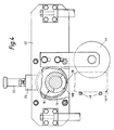
- Fig.4 shows the apparatus of Figs. 3A, 3B in end elevation as seen looking in the direction of container movement;
- Fig.5 similarly shows the apparatus of Figs. 3A, 3B looking backwardly towards the on-coming containers;
- Fig.6 is a view corresponding to Fig.2 of a first modified filling apparatus; and
- Fig.7 similarly shows a second modified filling apparatus.
- Referring firstly to Figs.1 and 2, a
filling apparatus 10 is shown in relation to open-topped containers 12 which are being moved from left to right (Fig.1) at a regular spacing and at a uniform speed along a horizontal path. The containers shown are metal cans, and the apparatus is being used for filling them with a liquid drink product. It is to be understood that after passing the apparatus the cans are moved to a seamer (not shown), by which they are closed by easy-opening end closures in conventional manner. - Briefly stated, the apparatus has a containment member in the form of an elongate
hollow tube 14 of substantially circular cross section which extends along and above the conveyor path and is closed byend caps 8, 9 at its ends. - A
metering screw 16 having ahelical thread 18 extends along and within the tube and is drivable to rotate by a motor (not shown) acting through ashaft 20 at the container exit end of the apparatus. - The
thread 18 hasseveral turns 18A of essentially rectangular contour (i.e. with acylindrical periphery 22 and radially directed flanks 24), which are separated byportions 18B of a continuous helical gap. The metering screw is located so that these turns make sliding contact with the base of the tube.Bearings 26 havingcompression springs 80 bias the metering screw downwardly to maintain this sliding contact at all times. - Along its base and laterally within its engagement by the turns of the metering screw, the tube is formed with an elongate,
continuous dispensing slot 28 typically 2mm in width. - As is clearly apparent from Fig.2, the metering screw has substantially smaller cross-sectional dimensions than the
tube 14 and occupies only a lower portion of the interior of the tube. Around the metering screw (with the exception of its sealing engagement with the metering screw and of its slot 28) the tube forms achamber 30 by which liquid product admitted via acentral supply conduit 32 may be distributed to thegaps 18B of the screw, so as to leave the apparatus through the parts of the dispensingslot 28 which at the time in question correspond axially with the gaps. - The rotation of the metering screw is synchronised with the movement of the containers along the path, with the result that each container in turn is subjected to a continuous and respective stream of liquid product which is first produced as the container passes beneath the upstream end of the
dispensing slot 28 and is terminated as the container passes the downstream end of the dispensing slot. - The product streams associated with adjacent containers are separated by a gap where a
turn 18A of themetering screw 16 makes sealing engagement with the interior of thetube 14 on each side of the dispensing slot 28 (in the circumferential direction of the tube). - Fig.2A shows to an enlarged scale the detail of the sealing engagement of the metering screw with the tube. Adjacent the sides of the slot the interior of the tube is formed with part-
circular sealing surfaces - Over most of the movement of each container beneath the
dispensing slot 28, the associated stream of liquid product has a width and length corresponding substantially and respectively to the width of the dispensing slot and to thescrew gap 18B. The screw gap is accordingly chosen to be substantially less than the container diameter. At the beginning and end of the movement the length of the stream increases in known manner from zero to full length, and vice versa, with the progressively varying correspondence of thegap 18B with the dispensing slot. - Whilst not apparent from the drawings it is to be understood that the liquid product to be filled into the
containers 12 is supplied to thedistribution chamber 30 via thesupply conduit 32 under a small hydrostatic pressure which ensures that the chamber is full of product at all times. - By control of the speed of movement of the containers and their respective product streams along the apparatus and/or the hydrostatic pressure of the liquid product, it is possible to control accurately the amount of liquid product which is filled into each container before it passes to the seamer for closing.
- If at any time it is desired to halt the filling operation, a valve (not shown) upstream of the supply conduit is closed and at the same time the drives for the metering screw and the containers to be filled are deenergized. Under such conditions no further product is dispensed, and leakage through the
dispensing slot 28 is prevented by surface tension of the product which holds the product within the tube against the small hydrostatic head which is present. For this purpose the width of thedispensing slot 28 is selected having in mind the surface properties of the product and the magnitude of the hydrostatic head. - Reference is now made to Figs.3 to 5 which show the apparatus in greater detail and with minor modifications not affecting its mode of operation. The apparatus is supported from the ground by
end plates drive scroll 44 when supported from beneath by adeadplate 46. The drive scroll is disposed on one side of the containers, the right hand side as seen in the downstream direction of the apparatus.Guide bars 48 define the limits of the container path on the opposite side of the containers. The pitch of the drive scroll is the same as that of themetering screw 16. - The
drive scroll 44 is supported bybearings electric motor 54 acting through, in succession,reduction gear 56,shaft 58,sprocket wheel 60,toothed belt 62,sprocket wheel 64 andshaft 66. The motor additionally drives themetering screw 16 throughsprocket wheel 68 on theshaft 58,toothed belt 70,sprocket wheel 72, andshaft 73. The drive scroll is extended beyond the metering screw at the entry end of the apparatus to ensure that the containers have a uniform and controlled movement as they approach the dispensing slot. - The two screws are thus driven in common by the same motor, and their drives are set to achieve the synchronisation previously described. Fine adjustment is provided by a
roller 74 which engages the exterior of thebelt 62 and the position of which (in relation to the belt) is adjustable bylocking bolts 76. - From Fig.4 the dispensing
slot 28 and its relationship to thetube 14 can be readily understood. The relative narrowness of the dispensing slot, and the manner in which it is closed off by themetering screw 16 except at thescrew gaps 18B are also apparent. It is preferred that the tube is of stainless steel and the metering screw is of a hard polymeric material such as PES (Poly Ether Sulphone). - The arrangement of each of the two spring-loaded
biassing bearings 26 is apparent from Fig.3A, which shows one of them in section. Each biassing bearing has apresser foot 78 which is biassed by acompression spring 80 downwardly into sliding contact with themetering screw 16 beneath. The spring is adjustably pre-loaded by settingbolt 82 and lockingnut 84. The presser foot has an axial extent which is somewhat greater than one thread pitch on thethread 18, so as at all times to engage the metering screw evenly, that is, without any tendency to tilt. An 'O'-ring 81 engages the presser foot to provide a fluid and gas-tight seal for the biassing bearing. - In order to allow the metering screw complete freedom to make sealing engagement with the interior of the
tube 14 as described, it is loose within the tube, that is to say, its ends are essentially unconstrained in the radial sense. Lateral location of the metering screw within the tube is provided by a combination of gravity, the hydrostatic pressure of the product, and thepresser feet 78 which engage the metering screw over a part-circular contact area (Fig.3A) to provide a centering action as well as a vertically downward biassing force. The rotary drive for the metering screw incorporates a transversely extendingdrive pin 86 and a driven member 87 (Fig.1) having aslot 88 in which the pin is located in a manner which allows the screw freedom to move both laterally and longitudinally. At its opposite end, i.e. at the entry end of the apparatus, the metering screw is free of any engagement except the desired sealing engagement with the tube interior and occasional brushing engagement of its plane end face 89 (Fig.1) with theend cap 8 for longitudinal location. - As particularly described above the apparatus shown in the drawings is designed for handling wholly liquid products having physical characteristics similar to those of water. However, the invention is not limited for use with such products; it may, for example, be adapted for use with liquid products which contain particulate or lumpy matter. As will be understood from the embodiment to be described with reference to Fig.7, for such products it will not be appropriate to rely upon surface tension to prevent leakage through the dispensing slot when the apparatus is inoperative, and a mechanical means such as a slide plate may be provided for that purpose.
- A particular advantage accruing from the substantially complete access and mobility of the metering screw within the containment member is the efficiency with which the internal surfaces of the apparatus can be cleaned. When cleaning is required , cleaning fluid is supplied to the
supply conduit 32 so as progressively to replace the liquid product within thetube 14 and subsequently to clean the interior surfaces of the apparatus. The cleaning fluid is then replaced by rinsing water in preparation for continued supply of the liquid product. Cleaning efficiency is further enhanced by hydraulic action exerted upwardly on thebiassing bearings 26 during cleaning. This relieves the pressure of thepresser feet 78 on the metering screw, and by reducing the contact forces at the engagement of the metering screw with thetube 14 allows the cleaning fluid or water, the case may be, to penetrate and treat the sealing interfaces. - Figs. 6 and 7 show the apparatus of Figs. 1 and 2 when modified for aseptic operation and respectively as arranged for dispensing a liquid product such as a fruit drink and a particulate product such as baked beans in tomato sauce.
- Referring firstly to Fig.6, the apparatus of Figs. 1 and 2 is modified by addition of a
slide plate 90. The slide plate has an elongate 'O'-ring 91 for sealing, and is mounted by guides (not shown) for movement between the operative position shown and the retracted position indicated by the broken line. The movement is achieved by anactuator 92 acting throughrod 95 and L-shapedcoupling member 96. The slide plate provides a movable entry end for apipe 97 in which a three-way valve 98 is mounted. Operation of the three-way valve enables the pipe to be connected selectively to a cleaning fluid vent or returnpipe 99, or asteam trap 100. - The slide plate is located in its retracted position for the normal dispensing of a liquid product; as described above, surface tension at the dispensing
slot 28 prevents product leakage during any interruption in the dispensing operation. However, when it is required to clean the apparatus internally the slide plate is advanced byactuator 92 to the position shown, so that the 'O'-ring 91 makes a fluid and gas tight seal with the underside oftube 14 on either side of the dispensingslot 28. - The liquid product supply to the
supply conduit 32 is then replaced by cleaning fluid which is passed via three-way valve 98 andpipe 99 initially to discharge and later to a CIP (Clean In Place) system associated with the apparatus. - After cleaning, the
valve 98 is operated and steam is admitted via thesupply conduit 32 to sterilise the interior of the apparatus and pass to steamtrap 100 which generates the back pressure required in the apparatus during sterilisation. After sterilisation, the steam is replaced by hot air which dries the interior surfaces of the apparatus and is vented through the steam trap. The slide plate is then retracted in preparation for the next product dispensing operation. - In the apparatus of Fig.7 the slide plate, now denoted 90', is extended to provide a shut-off portion 90'A with 'O'-
ring 101 for sealing. When located byactuator 92 beneath the dispensing slot the shut-off portion seals the latter against the escape of product during any interruption in the dispensing operation. The dispensing slot is somewhat wider than the dispensing slot of Fig.6, and accordingly it is denoted 28'. Theitems - Particularly for applications where high filling speeds are required, it may be advantageous to use two or more apparatus in accordance with the invention in series. Also, the thread of the metering screw may be a multistart thread if desired.
Claims (9)
- Apparatus for filling a flowable product into a succession of receptacles (12) as they pass continuously along a predetermined path, the apparatus comprising an elongate hollow containment member (14) mounted or mountable to extend along and above the container path and formed with an axially extending slot and a metering screw (16) having a helical thread (18) and mounted for rotation within the containment member (14), characterised in that the metering screw (16) is movable away from the slot (28) but biassed towards and into sealing engagement with the containment member (14) on each side of the slot, and a distribution chamber (30) is formed within the containment member substantially around the metering screw except at the sealing engagement and the slot whereby flowable product supplied to the distribution chamber when the metering screw is rotating may be distributed to pass through the slot between adjacent turns of the metering screw and leave the containment member as a succession of spaced moving streams.
- Apparatus in accordance with claim 1, characterised by a scroll (44) having the same thread pitch as the metering screw (16) and arranged to drive the receptacles (12) along the predetermined path in synchronism with the moving liquid streams.
- Apparatus in accordance with claim 1 or claim 2, characterised by a biassing means (78) operable upon the metering screw (16) to bias it downwardly into sealing engagement with the interior of the containment member (14).
- Apparatus in accordance with claim 3, characterised in that the biassing means (78) slidably engages the thread (18) of the metering screw (16).
- Apparatus in accordance with claim 3 or claim 4, characterised in that the metering screw (16) is laterally unconstrained within the containment member (14) except by the biassing means (78).
- Apparatus in accordance with any preceding claim, characterised by a shut-off means (90') operable for closing the dispensing slot.
- Apparatus in accordance with claim 6, characterised in that the shut-off means (90') is arranged alternatively to generate a back-pressure for sterilising medium admitted to the distribution chamber.
- A method of filling a flowable product into a succession of receptacles (12) as they pass continuously along a predetermined path, the method comprising rotating a metering screw (16) having a helical thread (18) within a containment member (14) having an elongate dispensing slot through which the liquid may issue between adjacent turns of the thread, characterised in that the metering screw (16) is movable and biassed so that the turns of its thread (18) make sealing engagement with the containment member (14) on either side of the slot (28), and the said flowable product is supplied to a distribution chamber (30) which is formed within the containment member substantially around the screw member except at the said sealing engagement.
- A method in accordance with claim 8, characterised in that when the supply of liquid to the chamber is interrupted and the metering screw (16) is non-rotating, any substantial flow of the liquid through the dispensing slot (28) is prevented by surface tension of the liquid in the vicinity of the dispensing slot.
Applications Claiming Priority (3)
| Application Number | Priority Date | Filing Date | Title |
|---|---|---|---|
| GB919113932A GB9113932D0 (en) | 1991-06-26 | 1991-06-26 | Filling liquids into receptalles |
| GB91139329 | 1991-06-26 | ||
| PCT/GB1992/001143 WO1993000263A1 (en) | 1991-06-26 | 1992-06-24 | Filling flowable products into receptacles |
Publications (2)
| Publication Number | Publication Date |
|---|---|
| EP0591396A1 EP0591396A1 (en) | 1994-04-13 |
| EP0591396B1 true EP0591396B1 (en) | 1995-12-20 |
Family
ID=10697458
Family Applications (1)
| Application Number | Title | Priority Date | Filing Date |
|---|---|---|---|
| EP92914359A Expired - Lifetime EP0591396B1 (en) | 1991-06-26 | 1992-06-24 | Filling flowable products into receptacles |
Country Status (8)
| Country | Link |
|---|---|
| US (1) | US5400836A (en) |
| EP (1) | EP0591396B1 (en) |
| JP (1) | JP3280668B2 (en) |
| AT (1) | ATE131784T1 (en) |
| CA (1) | CA2112223A1 (en) |
| DE (1) | DE69206989T2 (en) |
| GB (1) | GB9113932D0 (en) |
| WO (1) | WO1993000263A1 (en) |
Families Citing this family (6)
| Publication number | Priority date | Publication date | Assignee | Title |
|---|---|---|---|---|
| US5494085A (en) * | 1995-02-16 | 1996-02-27 | Zink; Arden K. | Container filling apparatus |
| US5989604A (en) * | 1996-12-19 | 1999-11-23 | Adore-A-Pet, Ltd. | Xylitol-containing non-human foodstuff and method |
| US7112449B1 (en) * | 2000-04-05 | 2006-09-26 | Nanogram Corporation | Combinatorial chemical synthesis |
| US20140021224A1 (en) * | 2010-11-18 | 2014-01-23 | Cavadistrib. Inc. | Dosing apparatus |
| EP3100955A1 (en) * | 2015-06-04 | 2016-12-07 | Cabinplant International A/S | A product dispenser and a method of dispensing a flowable product |
| JP6878924B2 (en) * | 2017-02-06 | 2021-06-02 | 大日本印刷株式会社 | Liquid feeding method, liquid feeding device and container filled with contents |
Family Cites Families (10)
| Publication number | Priority date | Publication date | Assignee | Title |
|---|---|---|---|---|
| US1420222A (en) * | 1919-02-17 | 1922-06-20 | Schmidt Arno | Can-filling machine |
| US2631768A (en) * | 1949-12-27 | 1953-03-17 | Dole Eng Co James | Filling apparatus and method |
| GB786366A (en) * | 1954-10-11 | 1957-11-13 | Dole Eng Co James | Filling apparatus and method |
| US2827928A (en) * | 1954-10-11 | 1958-03-25 | Dole Eng Co James | Filling apparatus |
| US2934101A (en) * | 1957-11-05 | 1960-04-26 | Dole Eng Co James | Product metering apparatus and method |
| US3442304A (en) * | 1966-04-28 | 1969-05-06 | Dole Eng Co James | Filling apparatus |
| SU761389A1 (en) * | 1977-11-09 | 1980-09-07 | Bashkirskij Selskokhoz I | SCREW CONVEYOR |
| US4387834A (en) * | 1979-10-01 | 1983-06-14 | Hpm Corporation | Combination thermoplastic and glass loaded thermosetting injection molding machine and method for operating same |
| SU1562239A1 (en) * | 1988-02-01 | 1990-05-07 | Всесоюзный научно-исследовательский и проектный институт алюминиевой, магниевой и электродной промышленности | Arrangement for unloading materials |
| GB2222150A (en) * | 1988-08-09 | 1990-02-28 | Exprocad Services Ltd | Apparatus suitable for dispensing or irradiating material etc |
-
1991
- 1991-06-26 GB GB919113932A patent/GB9113932D0/en active Pending
-
1992
- 1992-06-24 JP JP50140093A patent/JP3280668B2/en not_active Expired - Fee Related
- 1992-06-24 AT AT92914359T patent/ATE131784T1/en not_active IP Right Cessation
- 1992-06-24 CA CA002112223A patent/CA2112223A1/en not_active Abandoned
- 1992-06-24 US US08/170,242 patent/US5400836A/en not_active Expired - Fee Related
- 1992-06-24 DE DE69206989T patent/DE69206989T2/en not_active Expired - Fee Related
- 1992-06-24 WO PCT/GB1992/001143 patent/WO1993000263A1/en not_active Ceased
- 1992-06-24 EP EP92914359A patent/EP0591396B1/en not_active Expired - Lifetime
Also Published As
| Publication number | Publication date |
|---|---|
| JPH06509044A (en) | 1994-10-13 |
| JP3280668B2 (en) | 2002-05-13 |
| DE69206989D1 (en) | 1996-02-01 |
| US5400836A (en) | 1995-03-28 |
| ATE131784T1 (en) | 1996-01-15 |
| DE69206989T2 (en) | 1996-05-23 |
| CA2112223A1 (en) | 1993-01-07 |
| WO1993000263A1 (en) | 1993-01-07 |
| GB9113932D0 (en) | 1991-08-14 |
| EP0591396A1 (en) | 1994-04-13 |
Similar Documents
| Publication | Publication Date | Title |
|---|---|---|
| US9873603B2 (en) | Rotary filling apparatus and methods | |
| US5400836A (en) | Filling flowable products into receptacles | |
| KR100975679B1 (en) | Pouch pack automatic packing machine | |
| EP1520833A1 (en) | Machine for treatment of containers | |
| US11477993B2 (en) | Servo driven ice cream sandwich assembly and wrapping machine | |
| WO2012000573A1 (en) | Device for sterilizing closures for containers | |
| WO2015036186A1 (en) | Rotary feedthrough and device for treating and/or for transporting containers, said device having such a rotary feedthrough | |
| US2837127A (en) | Apparatus and method for filling containers with liquid | |
| US3894424A (en) | On line pressure testing system | |
| US3101752A (en) | Aseptic filling machine | |
| US2631768A (en) | Filling apparatus and method | |
| US5549143A (en) | Apparatus with vacuum recovery for adding flavor materials to beverages | |
| JP3064686B2 (en) | Method and pumping device for pumping products | |
| CN112499556A (en) | Full-automatic filling method and filling device for collateral activating oil | |
| US20050169796A1 (en) | Sterilizing device for sterilizing closures | |
| US2529199A (en) | Machine and method for hermetically sealing closure caps to containers | |
| GB2096113A (en) | Container filling machine | |
| EP3924292A1 (en) | Container-handling apparatus with a transportation element | |
| US3213901A (en) | Can filling method | |
| US2801651A (en) | Filling structure | |
| US3183887A (en) | Carton sealing apparatus and adhesive dispenser therefor | |
| US3872651A (en) | Overcap placer | |
| US3116765A (en) | Metering apparatus for filling containers | |
| US2859858A (en) | Sealing machine | |
| US3903938A (en) | Method of and apparatus for filling flowable material into open top containers |
Legal Events
| Date | Code | Title | Description |
|---|---|---|---|
| PUAI | Public reference made under article 153(3) epc to a published international application that has entered the european phase |
Free format text: ORIGINAL CODE: 0009012 |
|
| 17P | Request for examination filed |
Effective date: 19931209 |
|
| AK | Designated contracting states |
Kind code of ref document: A1 Designated state(s): AT BE CH DE DK ES FR GB GR IT LI LU NL SE |
|
| 17Q | First examination report despatched |
Effective date: 19950504 |
|
| RAP1 | Party data changed (applicant data changed or rights of an application transferred) |
Owner name: CARNAUDMETALBOX PLC |
|
| GRAA | (expected) grant |
Free format text: ORIGINAL CODE: 0009210 |
|
| AK | Designated contracting states |
Kind code of ref document: B1 Designated state(s): AT BE CH DE DK ES FR GB GR IT LI LU NL SE |
|
| PG25 | Lapsed in a contracting state [announced via postgrant information from national office to epo] |
Ref country code: NL Free format text: LAPSE BECAUSE OF FAILURE TO SUBMIT A TRANSLATION OF THE DESCRIPTION OR TO PAY THE FEE WITHIN THE PRESCRIBED TIME-LIMIT Effective date: 19951220 Ref country code: LI Effective date: 19951220 Ref country code: GR Free format text: LAPSE BECAUSE OF FAILURE TO SUBMIT A TRANSLATION OF THE DESCRIPTION OR TO PAY THE FEE WITHIN THE PRESCRIBED TIME-LIMIT Effective date: 19951220 Ref country code: ES Free format text: THE PATENT HAS BEEN ANNULLED BY A DECISION OF A NATIONAL AUTHORITY Effective date: 19951220 Ref country code: DK Effective date: 19951220 Ref country code: CH Effective date: 19951220 Ref country code: BE Effective date: 19951220 Ref country code: AT Effective date: 19951220 |
|
| REF | Corresponds to: |
Ref document number: 131784 Country of ref document: AT Date of ref document: 19960115 Kind code of ref document: T |
|
| REF | Corresponds to: |
Ref document number: 69206989 Country of ref document: DE Date of ref document: 19960201 |
|
| ET | Fr: translation filed | ||
| ITF | It: translation for a ep patent filed | ||
| PG25 | Lapsed in a contracting state [announced via postgrant information from national office to epo] |
Ref country code: SE Effective date: 19960320 |
|
| NLV1 | Nl: lapsed or annulled due to failure to fulfill the requirements of art. 29p and 29m of the patents act | ||
| PG25 | Lapsed in a contracting state [announced via postgrant information from national office to epo] |
Ref country code: LU Free format text: LAPSE BECAUSE OF NON-PAYMENT OF DUE FEES Effective date: 19960630 |
|
| PLBE | No opposition filed within time limit |
Free format text: ORIGINAL CODE: 0009261 |
|
| STAA | Information on the status of an ep patent application or granted ep patent |
Free format text: STATUS: NO OPPOSITION FILED WITHIN TIME LIMIT |
|
| 26N | No opposition filed | ||
| REG | Reference to a national code |
Ref country code: GB Ref legal event code: IF02 |
|
| PGFP | Annual fee paid to national office [announced via postgrant information from national office to epo] |
Ref country code: FR Payment date: 20020513 Year of fee payment: 11 |
|
| PGFP | Annual fee paid to national office [announced via postgrant information from national office to epo] |
Ref country code: GB Payment date: 20020520 Year of fee payment: 11 |
|
| PGFP | Annual fee paid to national office [announced via postgrant information from national office to epo] |
Ref country code: DE Payment date: 20020523 Year of fee payment: 11 |
|
| PG25 | Lapsed in a contracting state [announced via postgrant information from national office to epo] |
Ref country code: GB Free format text: LAPSE BECAUSE OF NON-PAYMENT OF DUE FEES Effective date: 20030624 |
|
| PG25 | Lapsed in a contracting state [announced via postgrant information from national office to epo] |
Ref country code: DE Free format text: LAPSE BECAUSE OF NON-PAYMENT OF DUE FEES Effective date: 20040101 |
|
| GBPC | Gb: european patent ceased through non-payment of renewal fee |
Effective date: 20030624 |
|
| PG25 | Lapsed in a contracting state [announced via postgrant information from national office to epo] |
Ref country code: FR Free format text: LAPSE BECAUSE OF NON-PAYMENT OF DUE FEES Effective date: 20040227 |
|
| REG | Reference to a national code |
Ref country code: FR Ref legal event code: ST |
|
| PG25 | Lapsed in a contracting state [announced via postgrant information from national office to epo] |
Ref country code: IT Free format text: LAPSE BECAUSE OF NON-PAYMENT OF DUE FEES Effective date: 20050624 |
|
| REG | Reference to a national code |
Ref country code: CH Ref legal event code: PL Ref country code: CH Ref legal event code: EP |