EP0589929B1 - Valve - Google Patents
Valve Download PDFInfo
- Publication number
- EP0589929B1 EP0589929B1 EP92911457A EP92911457A EP0589929B1 EP 0589929 B1 EP0589929 B1 EP 0589929B1 EP 92911457 A EP92911457 A EP 92911457A EP 92911457 A EP92911457 A EP 92911457A EP 0589929 B1 EP0589929 B1 EP 0589929B1
- Authority
- EP
- European Patent Office
- Prior art keywords
- valve member
- armature
- actuating element
- seating
- movement
- Prior art date
- Legal status (The legal status is an assumption and is not a legal conclusion. Google has not performed a legal analysis and makes no representation as to the accuracy of the status listed.)
- Expired - Lifetime
Links
- 238000004804 winding Methods 0.000 claims abstract description 15
- 239000012530 fluid Substances 0.000 claims abstract description 10
- 238000006243 chemical reaction Methods 0.000 claims description 10
- 230000008878 coupling Effects 0.000 claims description 2
- 238000010168 coupling process Methods 0.000 claims description 2
- 238000005859 coupling reaction Methods 0.000 claims description 2
- 230000006835 compression Effects 0.000 description 3
- 238000007906 compression Methods 0.000 description 3
- 230000002093 peripheral effect Effects 0.000 description 2
- 238000010276 construction Methods 0.000 description 1
- 238000013016 damping Methods 0.000 description 1
Images
Classifications
-
- F—MECHANICAL ENGINEERING; LIGHTING; HEATING; WEAPONS; BLASTING
- F02—COMBUSTION ENGINES; HOT-GAS OR COMBUSTION-PRODUCT ENGINE PLANTS
- F02M—SUPPLYING COMBUSTION ENGINES IN GENERAL WITH COMBUSTIBLE MIXTURES OR CONSTITUENTS THEREOF
- F02M59/00—Pumps specially adapted for fuel-injection and not provided for in groups F02M39/00 -F02M57/00, e.g. rotary cylinder-block type of pumps
- F02M59/44—Details, components parts, or accessories not provided for in, or of interest apart from, the apparatus of groups F02M59/02 - F02M59/42; Pumps having transducers, e.g. to measure displacement of pump rack or piston
- F02M59/46—Valves
- F02M59/466—Electrically operated valves, e.g. using electromagnetic or piezoelectric operating means
Definitions
- This invention relates to an electromagnetically operable fluid control valve of the ON/OFF type comprising a valve member movable between open and closed positions relative to a seating, an electromagnetic device including a stator assembly carrying a winding and an armature which is moved towards the stator assembly when the winding is energised, a return spring which is stressed during movement of the armature towards the stator assembly, means coupling the armature to the valve member said means comprises an actuating element engaged by said return spring and a valve member under travel spring interposed between said actuating element and the valve member and which yields to allow continued movement of the actuating element when the valve member engages the seating.
- DE-A-1194668 shows one form of such a valve in which movement of the valve member towards the seating is transmitted through a spring which yields to allow continued movement of the armature under the action of a return spring when the winding associated with the armature is de-energised.
- the winding is energised the extent of movement of the valve member away from its seating is determined by the engagement of the armature with a pole piece.
- the object of the present invention is to provide a control valve of the kind specified in an improved form.
- a control valve of the kind specified comprises an armature over travel spring interposed between the armature and said actuating element and stop means operable to limit the movement of the valve member away from the seating when said winding is energised, the armature over travel spring yielding to permit continued movement of the armature after said stop means has halted the movement of the valve member.
- valve comprises a valve section 10 and an actuator 11.
- the valve section 10 comprises a body 12 which is provided with a peripheral flange 13 which locates against the base wall of a recess 14 formed in a housing 15.
- the flange 13 of the body 12 is held against the base wall of the housing by an annular retaining member 15A which is screwed into the recess 14.
- the valve body 12 defines an open ended blind bore 16 which adjacent its blind end defines a seating 17 which surrounds an outlet 18. Moreover, adjacent the seating there is defined an annular gallery 19 which by way of passages 20 and slots 21 formed in the body communicates with an inlet passage 22 formed in the housing 15.
- a cup shaped valve member 24 Slidable in the bore 16 is a cup shaped valve member 24 the closed end of which is shaped for engagement with the seating 17.
- valve member is biased into engagement with the seating as will be explained, by a coiled compression spring 25 which engages the base wall of the valve member at one end and at its other end is located within a recess formed in the end portion of a valve actuating rod 26.
- the actuating rod is of stepped form with its end portion lying within the valve member being constructed as a sliding fit in the internal surface of the valve member and at its end remote from the valve member being provided with a screw thread.
- the valve actuating rod 26 carries a transversely extending pin 27 the end portions of which project into elongated slots 28 respectively which are formed in the wall of the valve member 24.
- the retaining member 15A is provided with an internal step between which and the valve body is located a stop plate 31 which also acts to transmit the clamping force generated when the retaining member 15A is tightened within the recess 14.
- the valve actuating rod 26 has a number of components mounted thereon the first of which adjacent the enlarged end portion of the rod which lies within the valve member, is a small washer 32 which extends with clearance through the central opening of the stop plate. Adjacent the washer is a reaction plate 33 and engaging the reaction plate is the end of a tubular extension of a spring abutment 34 which is engaged with the threaded portion of the actuating rod.
- the actuator includes a stator which carries windings which are energised when as will be explained, it is required to lift the valve member from the seating.
- a coiled compression spring 43 has one end engaging a tubular portion of the spring abutment 34 and its other end engaging a fixed abutment surface. Moreover, interposed between the spring abutment 34 and a pressure plate 44 which engages the inwardly extending flange 35 is a further coiled compression spring 45 which urges the flange into engagement with the reaction plate 33.
- the various components of the valve are shown in the positions which they adopt when the windings are de-energised. It will be seen that the reaction plate 33 is in engagement with the stop plate 31 and that the valve member is in engagement with the seating. A small clearance exists between the pin 27 and the end walls of the slots 28 so that the valve member is held in engagement with the seating due to the force exerted by the spring 25 and also by the fluid pressure acting on at least the annular end of the skirt of the valve member.
- the spring 45 tends to move the annular member and the armature in the direction towards the seating and this movement assists the movement of the actuating rod under the action of the spring 43 towards the seating.
- the valve member 24 will engage the seating and continued movement of the actuating rod under the action of the spring 43 will take place at the same time compressing the spring 25, until the reaction plate 33 engages the stop plate 31.
- the inertia of the actuating rod 26 together with the components connected to it and also the annular member and the armature is absorbed by the engagement of the reaction plate 33 with the stop plate 31 and not by the engagement of the valve member with the seating.
- valve member and the seating are therefore extended as compared with constructions in which the engagement of the valve member with the seating halts the movement of the various components of the valve.
- small mass of the valve member substantially eliminates valve bounce which could otherwise take place without proper damping.
Landscapes
- Engineering & Computer Science (AREA)
- Physics & Mathematics (AREA)
- Electromagnetism (AREA)
- Chemical & Material Sciences (AREA)
- Combustion & Propulsion (AREA)
- Mechanical Engineering (AREA)
- General Engineering & Computer Science (AREA)
- Magnetically Actuated Valves (AREA)
- Preventing Unauthorised Actuation Of Valves (AREA)
Abstract
Description
- This invention relates to an electromagnetically operable fluid control valve of the ON/OFF type comprising a valve member movable between open and closed positions relative to a seating, an electromagnetic device including a stator assembly carrying a winding and an armature which is moved towards the stator assembly when the winding is energised, a return spring which is stressed during movement of the armature towards the stator assembly, means coupling the armature to the valve member said means comprises an actuating element engaged by said return spring and a valve member under travel spring interposed between said actuating element and the valve member and which yields to allow continued movement of the actuating element when the valve member engages the seating.
- DE-A-1194668 shows one form of such a valve in which movement of the valve member towards the seating is transmitted through a spring which yields to allow continued movement of the armature under the action of a return spring when the winding associated with the armature is de-energised. When the winding is energised the extent of movement of the valve member away from its seating is determined by the engagement of the armature with a pole piece.
- The object of the present invention is to provide a control valve of the kind specified in an improved form.
- According to the invention a control valve of the kind specified comprises an armature over travel spring interposed between the armature and said actuating element and stop means operable to limit the movement of the valve member away from the seating when said winding is energised, the armature over travel spring yielding to permit continued movement of the armature after said stop means has halted the movement of the valve member.
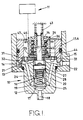
- An example of a control valve in accordance with the invention will now be described with reference to the accompanying drawing which is a part sectional side elevation of the valve.
- Referring to the drawing the valve comprises a
valve section 10 and anactuator 11. Thevalve section 10 comprises abody 12 which is provided with aperipheral flange 13 which locates against the base wall of arecess 14 formed in ahousing 15. Theflange 13 of thebody 12 is held against the base wall of the housing by an annular retainingmember 15A which is screwed into therecess 14. - The
valve body 12 defines an open endedblind bore 16 which adjacent its blind end defines aseating 17 which surrounds anoutlet 18. Moreover, adjacent the seating there is defined anannular gallery 19 which by way ofpassages 20 andslots 21 formed in the body communicates with aninlet passage 22 formed in thehousing 15. - Slidable in the
bore 16 is a cup shapedvalve member 24 the closed end of which is shaped for engagement with theseating 17. - The valve member is biased into engagement with the seating as will be explained, by a coiled
compression spring 25 which engages the base wall of the valve member at one end and at its other end is located within a recess formed in the end portion of a valve actuatingrod 26. The actuating rod is of stepped form with its end portion lying within the valve member being constructed as a sliding fit in the internal surface of the valve member and at its end remote from the valve member being provided with a screw thread. The valve actuatingrod 26 carries a transversely extendingpin 27 the end portions of which project intoelongated slots 28 respectively which are formed in the wall of thevalve member 24. - The retaining
member 15A is provided with an internal step between which and the valve body is located astop plate 31 which also acts to transmit the clamping force generated when the retainingmember 15A is tightened within therecess 14. - The valve actuating
rod 26 has a number of components mounted thereon the first of which adjacent the enlarged end portion of the rod which lies within the valve member, is asmall washer 32 which extends with clearance through the central opening of the stop plate. Adjacent the washer is areaction plate 33 and engaging the reaction plate is the end of a tubular extension of aspring abutment 34 which is engaged with the threaded portion of the actuating rod. - Engaging the outer peripheral portion of the reaction plate is an inturned flange 35 which is formed at the end of a
tubular member 36 which is coupled to an armature forming part of theactuator 11. The actuator includes a stator which carries windings which are energised when as will be explained, it is required to lift the valve member from the seating. - A coiled
compression spring 43 has one end engaging a tubular portion of thespring abutment 34 and its other end engaging a fixed abutment surface. Moreover, interposed between thespring abutment 34 and apressure plate 44 which engages the inwardly extending flange 35 is a further coiledcompression spring 45 which urges the flange into engagement with thereaction plate 33. - The extent of movement of the
tubular member 36 and the armature when the windings of the actuator are energised, is limited by anannular stop member 47 which is engaged by an outwardly extendingflange 46 on thetubular member 36. The stop member is held in position against the retainingmember 15A by means (not shown) for example, the body of theactuator 11. - The various components of the valve are shown in the positions which they adopt when the windings are de-energised. It will be seen that the
reaction plate 33 is in engagement with thestop plate 31 and that the valve member is in engagement with the seating. A small clearance exists between thepin 27 and the end walls of theslots 28 so that the valve member is held in engagement with the seating due to the force exerted by thespring 25 and also by the fluid pressure acting on at least the annular end of the skirt of the valve member. - When the winding is energised the force generated is transmitted to the valve actuating
rod 26 through thespring 45 and the actuating rod will be lifted together with all the components which are secured thereto, against the action of thespring 43. The upward movement will eventually take up the small clearance which exists between thepin 27 and the end walls of theslots 28 and when this clearance has been taken up the valve member is moved upwardly away from the seating thereby allowing flow of fluid through thevalve outlet 18. The movement of the valve member is halted by its engagement with thestop plate 31. This engagement will halt the movement of the actuating rod together with all the components connected thereto. However, continued movement of theannular member 36 and the armature can take place against the action of thespring 45, the eventual movement being halted by the engagement of theflange 46 with thestop member 47. The engagement of the flange with thestop member 47 leaves a small air gap between the faces of the armature and the stator of the actuator. Moreover, a gap will be established between the flange 35 and thereaction plate 33. - When the windings are de-energised, the
spring 45 tends to move the annular member and the armature in the direction towards the seating and this movement assists the movement of the actuating rod under the action of thespring 43 towards the seating. During the movement of the actuatingrod 26 thevalve member 24 will engage the seating and continued movement of the actuating rod under the action of thespring 43 will take place at the same time compressing thespring 25, until thereaction plate 33 engages thestop plate 31. The inertia of the actuatingrod 26 together with the components connected to it and also the annular member and the armature is absorbed by the engagement of thereaction plate 33 with thestop plate 31 and not by the engagement of the valve member with the seating. The life of the valve member and the seating is therefore extended as compared with constructions in which the engagement of the valve member with the seating halts the movement of the various components of the valve. Moreover, the small mass of the valve member substantially eliminates valve bounce which could otherwise take place without proper damping.
Claims (5)
- An electromagnetically operable fluid control valve of the ON/OFF type comprising a seating (17), a valve member (24) movable between open and closed positions relative to the seating, an electromagnetic device (11) including a stator assembly carrying a winding and an armature which is moved towards the stator assembly when the winding is energised, a return spring (43) which is stressed during movement of the armature towards the stator assembly, means coupling the armature to the valve member, said means comprising an actuating element (26) operatively connected to said return spring and a valve member under travel spring (25) interposed between said actuating element (26) and the valve member (24), said under travel spring yielding to allow continued movement of the actuating element when the valve member engages the seating, characterised by an armature over travel spring (45) interposed between the armature and said actuating element (26) and stop means (31) operable to limit the movement of the valve member away from the seating (17) when said winding is energised, the armature over travel spring (45) yielding to permit continued movement of the armature after said stop means (31) has halted the movement of the valve member.
- A fluid control valve according to Claim 1, characterised by further stop means (33, 31) acting to limit the movement of the actuating element (26) under the action of the return spring (45) when the winding is de-energised, said further stop means being positioned so that the valve member (24) engages with the seating (17) before the movement of the actuating element is halted by said further stop means.
- A fluid control valve according to Claim 2, characterised in that said stop means and said further stop means are defined by a stop plate (31) one face of which is engaged by the valve member (24) and the other face of which is engaged by a reaction plate (33) secured to the actuating element.
- A fluid control valve according to Claim 3, characterised by a member (36) coupled to the armature and defining an inturned flange (35) located between said reaction plate (33) and one end of the armature over travel spring (45), the other end of the armature over travel spring being engaged with a spring abutment (34) secured to the actuating element.
- A fluid control valve according to Claim 4, characterised by a pin and slot connection (27, 28) between said actuating element and said valve member.
Applications Claiming Priority (3)
| Application Number | Priority Date | Filing Date | Title |
|---|---|---|---|
| GB9113486 | 1991-06-21 | ||
| GB919113486A GB9113486D0 (en) | 1991-06-21 | 1991-06-21 | Valve |
| PCT/GB1992/001033 WO1993000540A1 (en) | 1991-06-21 | 1992-06-10 | Valve |
Publications (2)
| Publication Number | Publication Date |
|---|---|
| EP0589929A1 EP0589929A1 (en) | 1994-04-06 |
| EP0589929B1 true EP0589929B1 (en) | 1997-03-26 |
Family
ID=10697132
Family Applications (1)
| Application Number | Title | Priority Date | Filing Date |
|---|---|---|---|
| EP92911457A Expired - Lifetime EP0589929B1 (en) | 1991-06-21 | 1992-06-10 | Valve |
Country Status (7)
| Country | Link |
|---|---|
| EP (1) | EP0589929B1 (en) |
| AU (1) | AU1907492A (en) |
| CA (1) | CA2111986C (en) |
| DE (1) | DE69218598T2 (en) |
| ES (1) | ES2103372T3 (en) |
| GB (1) | GB9113486D0 (en) |
| WO (1) | WO1993000540A1 (en) |
Families Citing this family (7)
| Publication number | Priority date | Publication date | Assignee | Title |
|---|---|---|---|---|
| US5299776A (en) * | 1993-03-26 | 1994-04-05 | Siemens Automotive L.P. | Impact dampened armature and needle valve assembly |
| DE19816315A1 (en) * | 1998-04-11 | 1999-10-14 | Bosch Gmbh Robert | Fuel injector |
| DE19946602A1 (en) | 1999-09-29 | 2001-04-12 | Bosch Gmbh Robert | Fuel injector |
| ES2167275B1 (en) * | 2000-10-20 | 2003-10-16 | Bitron Ind Espana Sa | AIR FLOW REGULATORY ELECTROVALVULA. |
| DE10065528A1 (en) * | 2000-12-28 | 2002-07-04 | Bosch Gmbh Robert | Fuel injector |
| DE102005015737B4 (en) * | 2005-04-06 | 2016-02-04 | Robert Bosch Gmbh | Fuel injection valve for internal combustion engines |
| JP6015870B2 (en) * | 2012-02-20 | 2016-10-26 | 株式会社デンソー | Fuel injection valve |
Family Cites Families (4)
| Publication number | Priority date | Publication date | Assignee | Title |
|---|---|---|---|---|
| DE1194668B (en) * | 1960-02-12 | 1965-06-10 | Ranco Inc | Electromagnetically operated valve with shielding against vibrations |
| US3446246A (en) * | 1966-01-18 | 1969-05-27 | Dole Valve Co | Flow adjustment valve |
| US4746094A (en) * | 1986-11-13 | 1988-05-24 | Moog Inc. | Pulse-width-modulated solenoid valve |
| US4821774A (en) * | 1988-04-04 | 1989-04-18 | Chorkey William J | Solenoid operated valve with balancing means |
-
1991
- 1991-06-21 GB GB919113486A patent/GB9113486D0/en active Pending
-
1992
- 1992-06-10 WO PCT/GB1992/001033 patent/WO1993000540A1/en not_active Ceased
- 1992-06-10 EP EP92911457A patent/EP0589929B1/en not_active Expired - Lifetime
- 1992-06-10 AU AU19074/92A patent/AU1907492A/en not_active Abandoned
- 1992-06-10 ES ES92911457T patent/ES2103372T3/en not_active Expired - Lifetime
- 1992-06-10 DE DE69218598T patent/DE69218598T2/en not_active Expired - Lifetime
- 1992-06-10 CA CA002111986A patent/CA2111986C/en not_active Expired - Lifetime
Also Published As
| Publication number | Publication date |
|---|---|
| DE69218598T2 (en) | 1997-08-07 |
| CA2111986A1 (en) | 1993-01-07 |
| EP0589929A1 (en) | 1994-04-06 |
| WO1993000540A1 (en) | 1993-01-07 |
| DE69218598D1 (en) | 1997-04-30 |
| AU1907492A (en) | 1993-01-25 |
| CA2111986C (en) | 2001-05-29 |
| GB9113486D0 (en) | 1991-08-07 |
| ES2103372T3 (en) | 1997-09-16 |
Similar Documents
| Publication | Publication Date | Title |
|---|---|---|
| US6056264A (en) | Solenoid actuated flow control valve assembly | |
| EP0200373B1 (en) | High-pressure fluid control solenoid valve assembly with coaxially arranged two valves | |
| EP0321135B1 (en) | Control valve | |
| US4540155A (en) | Fluid control valves | |
| US5560549A (en) | Fuel injector electromagnetic metering valve | |
| US4831989A (en) | Control valve | |
| US5947442A (en) | Solenoid actuated valve assembly | |
| US5544815A (en) | Fuel injection Nozzle | |
| CN104685200B (en) | Valve module | |
| US5370355A (en) | Magnetic valve | |
| CA1125121A (en) | Fuel injection systems | |
| EP0690958A1 (en) | Impact dampened armature and needle valve assembly | |
| EP1042627A1 (en) | Servo-controlled magnetic valve | |
| EP0726390B1 (en) | Fuel system | |
| US5172887A (en) | Fluid control valve | |
| US4573659A (en) | Fluid control valve | |
| US4269388A (en) | Valve operating mechanism | |
| CA2111986C (en) | Valve | |
| US4690374A (en) | Magnetic valve for fluid control | |
| WO2002050424A3 (en) | Electromagnetic valve for controlling an injection valve of an internal combustion engine | |
| US20030111625A1 (en) | Magnetic valve for controlling an injection valve of an internal combustion engine | |
| EP0697518B1 (en) | Fuel injection nozzle | |
| US4763873A (en) | Fluid control valves | |
| GB2140129A (en) | Fluid control valves | |
| US4789131A (en) | Pilot valve |
Legal Events
| Date | Code | Title | Description |
|---|---|---|---|
| PUAI | Public reference made under article 153(3) epc to a published international application that has entered the european phase |
Free format text: ORIGINAL CODE: 0009012 |
|
| 17P | Request for examination filed |
Effective date: 19931209 |
|
| AK | Designated contracting states |
Kind code of ref document: A1 Designated state(s): DE ES FR GB IT |
|
| 17Q | First examination report despatched |
Effective date: 19950519 |
|
| GRAG | Despatch of communication of intention to grant |
Free format text: ORIGINAL CODE: EPIDOS AGRA |
|
| RAP1 | Party data changed (applicant data changed or rights of an application transferred) |
Owner name: LUCAS INDUSTRIES PUBLIC LIMITED COMPANY |
|
| GRAH | Despatch of communication of intention to grant a patent |
Free format text: ORIGINAL CODE: EPIDOS IGRA |
|
| GRAH | Despatch of communication of intention to grant a patent |
Free format text: ORIGINAL CODE: EPIDOS IGRA |
|
| GRAA | (expected) grant |
Free format text: ORIGINAL CODE: 0009210 |
|
| AK | Designated contracting states |
Kind code of ref document: B1 Designated state(s): DE ES FR GB IT |
|
| ITF | It: translation for a ep patent filed | ||
| REF | Corresponds to: |
Ref document number: 69218598 Country of ref document: DE Date of ref document: 19970430 |
|
| ET | Fr: translation filed | ||
| REG | Reference to a national code |
Ref country code: ES Ref legal event code: FG2A Ref document number: 2103372 Country of ref document: ES Kind code of ref document: T3 |
|
| PLBE | No opposition filed within time limit |
Free format text: ORIGINAL CODE: 0009261 |
|
| STAA | Information on the status of an ep patent application or granted ep patent |
Free format text: STATUS: NO OPPOSITION FILED WITHIN TIME LIMIT |
|
| 26N | No opposition filed | ||
| REG | Reference to a national code |
Ref country code: FR Ref legal event code: CD |
|
| REG | Reference to a national code |
Ref country code: GB Ref legal event code: 732E |
|
| REG | Reference to a national code |
Ref country code: FR Ref legal event code: TP |
|
| REG | Reference to a national code |
Ref country code: GB Ref legal event code: IF02 |
|
| PGFP | Annual fee paid to national office [announced via postgrant information from national office to epo] |
Ref country code: GB Payment date: 20030609 Year of fee payment: 12 |
|
| PGFP | Annual fee paid to national office [announced via postgrant information from national office to epo] |
Ref country code: ES Payment date: 20030619 Year of fee payment: 12 |
|
| PG25 | Lapsed in a contracting state [announced via postgrant information from national office to epo] |
Ref country code: GB Free format text: LAPSE BECAUSE OF NON-PAYMENT OF DUE FEES Effective date: 20040610 |
|
| PG25 | Lapsed in a contracting state [announced via postgrant information from national office to epo] |
Ref country code: ES Free format text: LAPSE BECAUSE OF NON-PAYMENT OF DUE FEES Effective date: 20040611 |
|
| GBPC | Gb: european patent ceased through non-payment of renewal fee |
Effective date: 20040610 |
|
| PG25 | Lapsed in a contracting state [announced via postgrant information from national office to epo] |
Ref country code: IT Free format text: LAPSE BECAUSE OF NON-PAYMENT OF DUE FEES Effective date: 20050610 |
|
| REG | Reference to a national code |
Ref country code: ES Ref legal event code: FD2A Effective date: 20040611 |
|
| REG | Reference to a national code |
Ref country code: FR Ref legal event code: TP |
|
| PGFP | Annual fee paid to national office [announced via postgrant information from national office to epo] |
Ref country code: FR Payment date: 20110621 Year of fee payment: 20 |
|
| PGFP | Annual fee paid to national office [announced via postgrant information from national office to epo] |
Ref country code: DE Payment date: 20110608 Year of fee payment: 20 |
|
| REG | Reference to a national code |
Ref country code: DE Ref legal event code: R071 Ref document number: 69218598 Country of ref document: DE |
|
| REG | Reference to a national code |
Ref country code: DE Ref legal event code: R071 Ref document number: 69218598 Country of ref document: DE |
|
| PG25 | Lapsed in a contracting state [announced via postgrant information from national office to epo] |
Ref country code: DE Free format text: LAPSE BECAUSE OF EXPIRATION OF PROTECTION Effective date: 20120612 |