EP0589730B1 - Electric lamp - Google Patents
Electric lamp Download PDFInfo
- Publication number
- EP0589730B1 EP0589730B1 EP19930307639 EP93307639A EP0589730B1 EP 0589730 B1 EP0589730 B1 EP 0589730B1 EP 19930307639 EP19930307639 EP 19930307639 EP 93307639 A EP93307639 A EP 93307639A EP 0589730 B1 EP0589730 B1 EP 0589730B1
- Authority
- EP
- European Patent Office
- Prior art keywords
- lamp
- annular
- base
- shell
- seal
- Prior art date
- Legal status (The legal status is an assumption and is not a legal conclusion. Google has not performed a legal analysis and makes no representation as to the accuracy of the status listed.)
- Expired - Lifetime
Links
Images

Classifications
-
- H—ELECTRICITY
- H01—ELECTRIC ELEMENTS
- H01J—ELECTRIC DISCHARGE TUBES OR DISCHARGE LAMPS
- H01J5/00—Details relating to vessels or to leading-in conductors common to two or more basic types of discharge tubes or lamps
- H01J5/50—Means forming part of the tube or lamps for the purpose of providing electrical connection to it
- H01J5/54—Means forming part of the tube or lamps for the purpose of providing electrical connection to it supported by a separate part, e.g. base
- H01J5/58—Means for fastening the separate part to the vessel, e.g. by cement
- H01J5/60—Means for fastening the separate part to the vessel, e.g. by cement for fastening by mechanical means
-
- H—ELECTRICITY
- H01—ELECTRIC ELEMENTS
- H01K—ELECTRIC INCANDESCENT LAMPS
- H01K1/00—Details
- H01K1/42—Means forming part of the lamp for the purpose of providing electrical connection, or support for, the lamp
- H01K1/46—Means forming part of the lamp for the purpose of providing electrical connection, or support for, the lamp supported by a separate part, e.g. base, cap
Definitions
- This invention relates to electric lamps.
- a lamp base comprises a metallic (e.g., aluminium) or plastic shell secured to an end portion of the lamp envelope.
- a metallic base shell at least one insulating disc is fixed in the shell for carrying one or more hollow base pins or contacts into which the lamp lead wires are electrically secured.
- the lamp is supported by a holder or socket into which the lamp base extends for connection to a source of electrical energy.
- each base is first fitted loosely onto a respective end portion of the lamp envelope. Thereafter, the cement is cured (e.g., by heating) which allows the base to adhere to the lamp bulb and withstand industry torque requirements.
- US-A-2,993,191 discloses a base for an electric discharge lamp wherein the base is constructed from resin having a modulus of elasticity which is greater than 5,000 kg/cm 2 and as high as about 19,000 kg/cm 2 .
- the resin has a breaking dilation of more than 50% and as high as about 230% and has an initial softening temperature of as low as about 150° Celsius and as high as about 210° Celsius.
- the base is positioned with the annular wall adjacent to the trough of a bulb end which has been heated to about 330° to 350° Celsius.
- the base material melts and occupies the trough or channel and by reason of the character of the material of which the base is composed, adheres to the surface of the glass bulb.
- the base may be pressed against the bulb end to cause an annular rib or reinforcement to snap over the bead or rim and into a trough or channel of the bulb without heating the bulb neck.
- US-A-4,221,453 discloses a socket capping (i.e., base) for a fluorescent lamp.
- the base comprises a frontal portion, contact pins electrically connected to the connecting wires, at least one drop of glue which dries at room temperature, and an annular wall extending circumferentially from and perpendicular to the frontal portion.
- the annular wall has at least two, equally circumferentially spaced knobs protruding inwardly.
- the base is formed from an elastic, bendable thermoplastic material so that when the base is fitted to the tube over the end portions, the annular wall elastically deforms and the knobs slide over the collar and snap into the groove of the lamp end portion.
- the base is formed with radial ribs to be disposed into notches provided in the bulb neck.
- a lamp comprising an envelope having an end portion onto which is sealed a lamp base, the end portion having an annular seal and the lamp base including a shell having an annular portion which is engaged with the annular seal so as to retain the lamp base on the envelope in a sealing condition, the shell having been heated to facilitate engagement of the annular portion over the seal and subsequently cooled to effect an interference fit with the seal.
- the present invention is characterised in that the shell is a metallic material.
- a lamp i.e., an incandescent lamp, a fluorescent lamp, a high intensity discharge lamp, etc.
- a lamp base comprising a metallic base shell having an annular flange with a relatively smooth inner surface, insulating means secured to the base shell, and base pin or contact means mounted on the insulating means for connection to a source of power.
- the inner diameter of the annular flange is such that when the base shell is heated prior to fitting of the annular flange over the end portion the diameter of the annular flange increases to an expanded diameter. After the annular flange is cooled following fitting, the annular flange forms an interference fit with the end portion so as to retain the lamp base on the end portion in a cement-free manner.
- the annular flange includes an annular rib on the inner surface thereof.
- the inner diameter of the annular rib is such that when the annular flange is heated prior to fitting of the annular flange over the end portion, the inner diameter of the annular rib increases to an expanded diameter. After the annular flange is cooled following fitting, the annular rib forms an interference fit with the end portion so as to retain the lamp base on the end portion in a cement-free manner.
- the method comprises the steps of providing an hermetically sealed glass envelope having at least one end portion which includes an annular groove and a terminating annular seal; providing a lamp base comprising a metallic base shell having an annular flange with an inner surface, insulating means secured to the base shell, and base pin or contact means mounted on the insulating means; heating the annular flange to a predetermined temperature so as to increase the predetermined minimum diameter of the annular flange to an expanded diameter; thereafter, fitting the annular flange over the end portion; and cooling the annular flange so that the inner surface thereof forms an interference fit with the end portion so as to retain the lamp base on the end portion in a cement-free manner.
- the method for manufacturing the lamp includes the step of forming an annular rib on the inner surface of the annular flange and fitting the annular flange over the end portion so that the annular rib is adjacent to the annular groove and the annular seal.
- FIGS. 1 and 2 there is shown in FIGS. 1 and 2 a lamp 10 (i.e., a fluorescent tube) comprising a tubular vitreous or glass envelope 12 that is provided with an inner coating of phosphor 14 and is hermetically sealed at each end by a glass mount 16.
- Each mount 16 includes a stem press 18 within which a pair of lead wires 20 are sealed.
- a thermionic electrode 22 is mounted on the inner ends of lead wires 20 within the tubular glass envelope 12.
- Each thermionic electrode 22 comprises a tungsten coil coated with an emissive material of alkaline earth oxides.
- the envelope 12 is filled with a suitable starting gas and also doped with mercury to provide an ionizable medium within the sealed envelope which permits an electric discharge to pass between the thermionic electrodes.
- each of the end portions of the lamp envelope 12 includes an annular groove 34 which terminates at an annular rim or seal 38, in the form of a bead, which has a diameter D S .
- Each of the sealed end portions of envelope 12 are fitted with a base 30 that includes a pair of axially-extending metal base pins 32 or other form of contacts which serve as terminals for the lamp 10 and are adapted, by virtue of their spacing and dimensions, to permit the lamp to be inserted into the socket components of a lighting fixture and be operated from a suitable electrical power supply.
- Each lead wire 20 extends through a stem press 18 in mount 16 to a respective metal base pin 32.
- Base 30 includes a metallic base shell 42 having a circumferential annular flange 44 with an inner diameter D F .
- Annular flange 44 which extends axially, has a relatively smooth inner surface 40 in the embodiment of FIG. 2.
- Surface 40 in FIG. 2 is smooth in the sense that this surface is free of any bumps or other protrusions.
- Base shell 42 is formed of a suitable metal such as aluminium, which has a modulus of elasticity which is between 6.32 x 10 5 kg/cm 2 and 4.03 x 10 6 kg/cm 2 . Aluminium has a breaking dilation of 14% minimum and a melting temperature of 660° Celsius.
- An oval-shaped disc 46 of insulating material is secured to base shell 42.
- a pair of base pins 32 are received in registering apertures formed in the insulating disc 46.
- each of the base pins 32 are provided with an upset collar portion 48 engaging the lower surface of disc 46 and having their inner ends swaged or riveted into contact with the upper surface of disc 46, in the region of apertures in the shell 42, thus rigidly securing the pins in position whilst insulating them from shell 42.
- each base pin may be mounted on separate insulating disks.
- the inner diameter D F of the annular flange 44 prior to fitting over the lamp end portion is slightly smaller than the annular seal diameter D S .
- the annular flange 44 is heated to a temperature of, for example, 260°C to 315°C.
- the inner diameter D F of the annular flange 44 increases to an expanded diameter and allows the annular flange 44 to easily slide over the annular seal 38.
- annular flange 44 of the base shell 42 is allowed to cool, whereupon annular flange 44 contracts to its initial diameter D F causing formation of an interference fit between the inner surface 40 of annular flange 44 and the annular seal 38. It has been discovered that this interference fit alone is sufficient to secure the lamp base to the lamp end portion. Bases fitted in this manner have passed prescribed torsion tests. No cements, glues or other adhesives were needed.
- the base of FIG. 2 is particularly suited to lamps wherein the shape of the annular seal and, more particularly, the outer diameter is precisely controlled as is the case where the annular seal is formed in a moulded-type operation.
- the lamp included a tubular glass envelope having an outer diameter of 3.744 cm.
- One of the lamp end portions contains an annular seal having an outer diameter of 3.423 cm.
- the base includes an aluminium base shell having an annular flange with an inner diameter (at room temperature and prior to fitting) of 3.399 cm.
- the annular flange is heated to a temperature of 288°C whereupon the inner diameter of the annular flange increased to 3.419 cm. Thereafter, the heated annular flange is fitted over the end portion of the lamp and allowed to cool. Upon cooling, the inner surface of the annular flange contacted the annular lamp seal and forms an interference fit.
- FIG. 3 there is shown a lamp base 30' according to another embodiment of the present invention, wherein similar constituent members as those in FIG. 2 are denoted by the same reference numerals.
- the annular flange 44 includes a groove or channel 50 formed in its outer surface which provides an annular rib 52 on the inner surface.
- Groove 50 may be formed by placing the base on a split, spring-loaded mandrel having an annular groove.
- the annular groove in the mandrel has a depth equal to the maximum intended height of annular rib.
- a clamshell clamp with a tooth corresponding to the maximum rib height contacts the annular flange at the intersection of the tooth and the annular groove formed in the mandrel.
- the depth of the groove formed in the base flange (and consequently the height of the annular rib in the base flange) is controlled by a force gauge or a linear distance sensor.
- the groove and annular rib in the base flange may be formed manually by using a hand tool with a tooth formed in one leg.
- the radius of the tooth is equal to the outer diameter of the base flange.
- a groove formed in the other leg of the tool to receive the tooth has the desired shape of the annular rib.
- the cross-sectional shape of the annular rib 52 may be varied.
- the cross-sectional shape of rib 52 may be square (FIG. 4A), triangular (FIGS. 3 and 4B) or have a leading edge 62 tapered at approximately 45° with respect to the base flange to assist fitting (FIG. 4C). Varying the cross-sectional shape of the annular rib 52 may result in reduced fitting force and additional retention and anti-rotation forces.
- the inner diameter D R of the annular rib 52 prior to fitting over the lamp end portion is slightly smaller than the annular seal diameter D S .
- the annular flange 44 is heated to a temperature of, for example, 260°C to 315°C.
- the inner diameter D R of the annular rib 52 increases to an expanded diameter which allows the annular rib 52 to slide over the annular seal 38 and into annular groove 34 adjacent to annular seal 38.
- the end portion of the lamp may be at room temperature or at an elevated temperature during base fitting.
- annular flange 44 of the base shell 42 is allowed to cool, whereupon annular rib 52 forms an interference fit with the lamp end portion.
- Bases fitted in this manner have passed prescribed torsion tests without the need for cement, glue or other form of adhesive.
- the following Table illustrates typical rib dimensions for various lamp seal diameters D S .
- the inner diameter D R of the annular rib is shown at 25°C and 288°C.
- the inner diameter D F of the annular flange measured prior to the formation of the annular rib is equal to approximately 3.399 cm.
- Rib height in the second column is equal to (D F -D R )/ 2 .
- changes to the height and/or shape of the annular rib may be made by the use of supplemental jaws containing a tooth.
- the circumferential radius of the jaws should approximate to the smallest dimension of the annular groove in the base shell.
- Sufficient pressure is applied on the base shell by the jaws to deepen or reshape the existing annular groove and further force the annular rib against the lamp end portion.
- Such changes to the annular rib after base fitting further increases retention and anti-rotation forces.
- the base can easily be secured to the lamp end without the need for basing cement or other type of adhesive.
- the base can be used without the need for special notching of the bulb neck in order to prevent rotary movement of the base relative to the bulb.
Landscapes
- Common Detailed Techniques For Electron Tubes Or Discharge Tubes (AREA)
- Vessels And Coating Films For Discharge Lamps (AREA)
Description
- This invention relates to electric lamps.
- In the manufacture of lamps, the lamp envelope is usually provided with a base. Generally, a lamp base comprises a metallic (e.g., aluminium) or plastic shell secured to an end portion of the lamp envelope. In the case of a metallic base shell, at least one insulating disc is fixed in the shell for carrying one or more hollow base pins or contacts into which the lamp lead wires are electrically secured. The lamp is supported by a holder or socket into which the lamp base extends for connection to a source of electrical energy.
- Typically, such lamp bases are secured to the end portion of the lamp envelope by means of a cement which is applied to the inside surface of the base shell. A sufficient quantity of cement is used to fill in the gap between the lamp seal and the annular wall of the base. During manufacturing, each base is first fitted loosely onto a respective end portion of the lamp envelope. Thereafter, the cement is cured (e.g., by heating) which allows the base to adhere to the lamp bulb and withstand industry torque requirements.
- While the above technique of securing the lamp base by means of a suitable cement has been employed successfully in many lamp families including fluorescent, it has been found that certain disadvantages do exist. For example, the cement not only adds cost to the lamp but also requires the need for a separate process of applying the raw cement to the base shell. Moreover, while present manufacturing facilities using such a technique are equipped with machines which dispense cement, these machines require constant monitoring and periodic mechanical and electrical maintenance. Another disadvantage is the curing process of the cement wherein indirect natural gas flame heat is used to cure the basing cement after the base is fitted to the end of the lamp. The temperatures required to cure the cement sometimes cause damage in the seal area of the lamp envelope. In addition, the machinery needed to provide the heat for curing not only requires periodic maintenance but also takes up valuable floor space in the production line.
- Various alternatives for securing the base to the lamp end with little or no cement (or other type of adhesive) have been proposed in the past. For example, US-A-2,993,191 discloses a base for an electric discharge lamp wherein the base is constructed from resin having a modulus of elasticity which is greater than 5,000 kg/cm2 and as high as about 19,000 kg/cm2. The resin has a breaking dilation of more than 50% and as high as about 230% and has an initial softening temperature of as low as about 150° Celsius and as high as about 210° Celsius. In one embodiment, the base is positioned with the annular wall adjacent to the trough of a bulb end which has been heated to about 330° to 350° Celsius. As a result, the base material melts and occupies the trough or channel and by reason of the character of the material of which the base is composed, adheres to the surface of the glass bulb. Alternatively, the base may be pressed against the bulb end to cause an annular rib or reinforcement to snap over the bead or rim and into a trough or channel of the bulb without heating the bulb neck.
- US-A-4,221,453 discloses a socket capping (i.e., base) for a fluorescent lamp. The base comprises a frontal portion, contact pins electrically connected to the connecting wires, at least one drop of glue which dries at room temperature, and an annular wall extending circumferentially from and perpendicular to the frontal portion. The annular wall has at least two, equally circumferentially spaced knobs protruding inwardly. The base is formed from an elastic, bendable thermoplastic material so that when the base is fitted to the tube over the end portions, the annular wall elastically deforms and the knobs slide over the collar and snap into the groove of the lamp end portion. To safeguard against rotary movement of the base relative to the bulb, the base is formed with radial ribs to be disposed into notches provided in the bulb neck.
- While the bases described in the above patents appear to be satisfactory from a functional standpoint, it is believed that unanticipated production or other related problems (e.g., material cost) may explain why such bases have not been commercially successful. Accordingly, it would be advantageous to provide other viable alternatives.
- It is known from FR-A-2,558,008 to provide a lamp comprising an envelope having an end portion onto which is sealed a lamp base, the end portion having an annular seal and the lamp base including a shell having an annular portion which is engaged with the annular seal so as to retain the lamp base on the envelope in a sealing condition, the shell having been heated to facilitate engagement of the annular portion over the seal and subsequently cooled to effect an interference fit with the seal.
- The present invention is characterised in that the shell is a metallic material.
- In one embodiment there is provided a lamp (i.e., an incandescent lamp, a fluorescent lamp, a high intensity discharge lamp, etc.) comprising a glass envelope having at least one end portion. The end portion or portions have an annular groove and a terminating annular seal having a predetermined diameter. Disposed at the end portion is a lamp base comprising a metallic base shell having an annular flange with a relatively smooth inner surface, insulating means secured to the base shell, and base pin or contact means mounted on the insulating means for connection to a source of power. The inner diameter of the annular flange is such that when the base shell is heated prior to fitting of the annular flange over the end portion the diameter of the annular flange increases to an expanded diameter. After the annular flange is cooled following fitting, the annular flange forms an interference fit with the end portion so as to retain the lamp base on the end portion in a cement-free manner.
- In accordance with further possible features, the annular flange includes an annular rib on the inner surface thereof. The inner diameter of the annular rib is such that when the annular flange is heated prior to fitting of the annular flange over the end portion, the inner diameter of the annular rib increases to an expanded diameter. After the annular flange is cooled following fitting, the annular rib forms an interference fit with the end portion so as to retain the lamp base on the end portion in a cement-free manner.
- There is also provided a method for manufacturing a lamp. The method comprises the steps of providing an hermetically sealed glass envelope having at least one end portion which includes an annular groove and a terminating annular seal; providing a lamp base comprising a metallic base shell having an annular flange with an inner surface, insulating means secured to the base shell, and base pin or contact means mounted on the insulating means; heating the annular flange to a predetermined temperature so as to increase the predetermined minimum diameter of the annular flange to an expanded diameter; thereafter, fitting the annular flange over the end portion; and cooling the annular flange so that the inner surface thereof forms an interference fit with the end portion so as to retain the lamp base on the end portion in a cement-free manner.
- In one possible arrangement, the method for manufacturing the lamp includes the step of forming an annular rib on the inner surface of the annular flange and fitting the annular flange over the end portion so that the annular rib is adjacent to the annular groove and the annular seal.
- Some embodiments of the invention will now be described by way of example and with reference to the accompanying drawings, in which:-
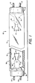
- FIG. 1 represents a front elevational view, partially broken away, of an arc discharge lamp made in accordance with the teachings of the present invention;
- FIG. 2 is an enlarged sectional view of one end of the arc discharge lamp shown in FIG. 1 illustrating one embodiment of an improved lamp base;
- FIG. 3 is an enlarged sectional view of one end of an arc discharge lamp illustrating another embodiment of an improved lamp base wherein an annular rib is formed on the inner surface of the annular flange; and
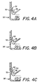
- FIGS. 4A, 4B and 4C are enlarged sectional views of an arc discharge lamp illustrating alternative embodiments of an improved lamp base having an annular rib.
- Referring now to the drawings in greater detail, there is shown in FIGS. 1 and 2 a lamp 10 (i.e., a fluorescent tube) comprising a tubular vitreous or
glass envelope 12 that is provided with an inner coating ofphosphor 14 and is hermetically sealed at each end by aglass mount 16. Eachmount 16 includes astem press 18 within which a pair oflead wires 20 are sealed. Athermionic electrode 22 is mounted on the inner ends oflead wires 20 within thetubular glass envelope 12. Eachthermionic electrode 22 comprises a tungsten coil coated with an emissive material of alkaline earth oxides. - In accordance with standard lamp-making practice, the
envelope 12 is filled with a suitable starting gas and also doped with mercury to provide an ionizable medium within the sealed envelope which permits an electric discharge to pass between the thermionic electrodes. - As shown more particularly in the enlarged sectional view of one end of the
fluorescent lamp 10 illustrated in FIG. 2, each of the end portions of thelamp envelope 12 includes anannular groove 34 which terminates at an annular rim orseal 38, in the form of a bead, which has a diameter DS. Each of the sealed end portions ofenvelope 12 are fitted with abase 30 that includes a pair of axially-extendingmetal base pins 32 or other form of contacts which serve as terminals for thelamp 10 and are adapted, by virtue of their spacing and dimensions, to permit the lamp to be inserted into the socket components of a lighting fixture and be operated from a suitable electrical power supply. Eachlead wire 20 extends through astem press 18 inmount 16 to a respectivemetal base pin 32. -
Base 30 includes ametallic base shell 42 having a circumferentialannular flange 44 with an inner diameter DF.Annular flange 44, which extends axially, has a relatively smoothinner surface 40 in the embodiment of FIG. 2.Surface 40 in FIG. 2 is smooth in the sense that this surface is free of any bumps or other protrusions. When thebase 30 of FIG. 2 is secured to the lamp end portion in a manner to be described below, theinner surface 40 of theannular flange 44 contactsannular seal 38.Base shell 42 is formed of a suitable metal such as aluminium, which has a modulus of elasticity which is between 6.32 x 10⁵ kg/cm2 and 4.03 x 10⁶ kg/cm2. Aluminium has a breaking dilation of 14% minimum and a melting temperature of 660° Celsius. - An oval-
shaped disc 46 of insulating material is secured tobase shell 42. A pair ofbase pins 32 are received in registering apertures formed in theinsulating disc 46. As illustrated in FIG. 2, each of thebase pins 32 are provided with anupset collar portion 48 engaging the lower surface ofdisc 46 and having their inner ends swaged or riveted into contact with the upper surface ofdisc 46, in the region of apertures in theshell 42, thus rigidly securing the pins in position whilst insulating them fromshell 42. - While the
base 30 is shown including two base pin, any number of pins may be used depending upon the type of lamp being manufactured. Also, while only one insulating disc is used in the base illustrated in FIG. 2, it is understood that each base pin may be mounted on separate insulating disks. - At room temperature (i.e., 25°C), the inner diameter DF of the
annular flange 44 prior to fitting over the lamp end portion is slightly smaller than the annular seal diameter DS. During lamp manufacturing and prior to fitting the lamp base over the end portion, theannular flange 44 is heated to a temperature of, for example, 260°C to 315°C. In response to the heat, the inner diameter DF of theannular flange 44 increases to an expanded diameter and allows theannular flange 44 to easily slide over theannular seal 38. Thereafter, theannular flange 44 of thebase shell 42 is allowed to cool, whereuponannular flange 44 contracts to its initial diameter DF causing formation of an interference fit between theinner surface 40 ofannular flange 44 and theannular seal 38. It has been discovered that this interference fit alone is sufficient to secure the lamp base to the lamp end portion. Bases fitted in this manner have passed prescribed torsion tests. No cements, glues or other adhesives were needed. - The base of FIG. 2 is particularly suited to lamps wherein the shape of the annular seal and, more particularly, the outer diameter is precisely controlled as is the case where the annular seal is formed in a moulded-type operation.
- In a typical but non-limiting example of an arc discharge lamp in accordance with the teachings of the above embodiment, the lamp included a tubular glass envelope having an outer diameter of 3.744 cm. One of the lamp end portions contains an annular seal having an outer diameter of 3.423 cm. The base includes an aluminium base shell having an annular flange with an inner diameter (at room temperature and prior to fitting) of 3.399 cm. The annular flange is heated to a temperature of 288°C whereupon the inner diameter of the annular flange increased to 3.419 cm. Thereafter, the heated annular flange is fitted over the end portion of the lamp and allowed to cool. Upon cooling, the inner surface of the annular flange contacted the annular lamp seal and forms an interference fit.
- Referring next to FIG. 3, there is shown a lamp base 30' according to another embodiment of the present invention, wherein similar constituent members as those in FIG. 2 are denoted by the same reference numerals.
- In order to better accommodate normal variations in the diameter of lamp seals, the
annular flange 44 includes a groove orchannel 50 formed in its outer surface which provides anannular rib 52 on the inner surface. -
Groove 50 may be formed by placing the base on a split, spring-loaded mandrel having an annular groove. The annular groove in the mandrel has a depth equal to the maximum intended height of annular rib. A clamshell clamp with a tooth corresponding to the maximum rib height contacts the annular flange at the intersection of the tooth and the annular groove formed in the mandrel. The depth of the groove formed in the base flange (and consequently the height of the annular rib in the base flange) is controlled by a force gauge or a linear distance sensor. - Alternatively, the groove and annular rib in the base flange may be formed manually by using a hand tool with a tooth formed in one leg. The radius of the tooth is equal to the outer diameter of the base flange. A groove formed in the other leg of the tool to receive the tooth has the desired shape of the annular rib.
- It is to be understood that the cross-sectional shape of the
annular rib 52 may be varied. For example, the cross-sectional shape ofrib 52 may be square (FIG. 4A), triangular (FIGS. 3 and 4B) or have aleading edge 62 tapered at approximately 45° with respect to the base flange to assist fitting (FIG. 4C). Varying the cross-sectional shape of theannular rib 52 may result in reduced fitting force and additional retention and anti-rotation forces. - At room temperature, the inner diameter DR of the
annular rib 52 prior to fitting over the lamp end portion is slightly smaller than the annular seal diameter DS. During lamp manufacturing and prior to fitting the lamp base over the end portion, theannular flange 44 is heated to a temperature of, for example, 260°C to 315°C. As a result of heating the base flange, the inner diameter DR of theannular rib 52 increases to an expanded diameter which allows theannular rib 52 to slide over theannular seal 38 and intoannular groove 34 adjacent toannular seal 38. The end portion of the lamp may be at room temperature or at an elevated temperature during base fitting. Thereafter, theannular flange 44 of thebase shell 42 is allowed to cool, whereuponannular rib 52 forms an interference fit with the lamp end portion. Bases fitted in this manner have passed prescribed torsion tests without the need for cement, glue or other form of adhesive. - The following Table illustrates typical rib dimensions for various lamp seal diameters DS. The inner diameter DR of the annular rib is shown at 25°C and 288°C. In each case, the inner diameter DF of the annular flange measured prior to the formation of the annular rib is equal to approximately 3.399 cm. Rib height in the second column is equal to (DF-DR)/2.
TABLE Avg. Seal Diameter DS Approx. Rib Height Inner Diam. Of Annular Rib @ 25°C @ 288°C 3.40 0.028 3.340 3.358 3.38 0.036 3.327 3.345 3.35 0.048 3.302 3.320 3.33 0.061 3.277 3.294 3.30 0.074 3.251 3.269 3.28 0.086 3.226 3.243 3.25 0.099 3.200 3.218 3.23 0.112 3.175 3.193 3.20 0.124 3.150 3.167 - After the base is fitted to the lamp end portion in the manner described above, changes to the height and/or shape of the annular rib may be made by the use of supplemental jaws containing a tooth. The circumferential radius of the jaws should approximate to the smallest dimension of the annular groove in the base shell. Sufficient pressure is applied on the base shell by the jaws to deepen or reshape the existing annular groove and further force the annular rib against the lamp end portion. Such changes to the annular rib after base fitting further increases retention and anti-rotation forces.
- There has thus been shown and described a lamp having an interference-fit metallic base. The base can easily be secured to the lamp end without the need for basing cement or other type of adhesive. The base can be used without the need for special notching of the bulb neck in order to prevent rotary movement of the base relative to the bulb.
- While there have been shown and described what are at present considered to be the preferred embodiments of the invention, it will be apparent to those skilled in the art that various changes and modifications can be made herein without departing from the scope of the invention. For example, while the drawings illustrate a fluorescent lamp, it is understood that the teachings can also be applied to other lamp types.
Claims (9)
- A lamp (10) comprising an envelope (12) having an end portion onto which is sealed a lamp base (30), the end portion having an annular seal (38) and the lamp base (30) including a shell (42) having an annular portion (40;52) which is engaged with the annular seal (38) so as to retain the lamp base (30) on the envelope (12) in a sealing condition, the shell (42) having been heated to facilitate engagement of the annular portion (40;52) over the seal (38) and subsequently cooled to effect an interference fit with the seal (38), characterised in that the shell is a metallic material.
- A lamp as claimed in claim 1, characterised in that the base shell (42) is of aluminium.
- A lamp as claimed in claim 1 or 2, characterised in that the seal (38) on the end portion of the envelope (12) is in the form of an annular bead.
- A lamp as claimed in claim 3, characterised in that the annular bead is connected to the remainder of the envelope (12) by an annular groove (34).
- A lamp as claimed in any preceding claim, characterised in that the annular portion (40) of the shell (42) is a relatively smooth inner surface (40) of an axially extending flange (44).
- A lamp as claimed in any preceding claim, characterised in that the annular portion (52) of the shell (42) is an inwardly directed rib (52) on an axially extending flange (44), which rib (52) engages in a groove (34) in the end portion of the envelope (12).
- A lamp as claimed in claim 6, characterised in that the leading edge (62) of the rib (52) is tapered.
- A method of manufacturing a lamp as claimed in any preceding claim, characterised in that the metallic shell (42) is heated to a temperature in the range of 260°C to 315°C to permit the annular portion (40;52) to increase in diameter, fitted over the seal (38) and then cooled.
- A method of manufacturing a lamp as claimed in claim 6 or 7, characterised in that after the metallic shell (42) has been heated and fitted over the seal (38) with the rib (52) engaged in the groove (34), the rib (52) is further pressed into the groove (34).
Applications Claiming Priority (4)
| Application Number | Priority Date | Filing Date | Title |
|---|---|---|---|
| US951509 | 1992-09-25 | ||
| US07/951,521 US5432400A (en) | 1992-09-25 | 1992-09-25 | Lamp having interference-fit metallic bases |
| US951521 | 1992-09-25 | ||
| US07/951,509 US5254025A (en) | 1992-09-25 | 1992-09-25 | Method for manufacturing lamp having interference-fit metallic bases |
Publications (2)
| Publication Number | Publication Date |
|---|---|
| EP0589730A1 EP0589730A1 (en) | 1994-03-30 |
| EP0589730B1 true EP0589730B1 (en) | 1996-12-04 |
Family
ID=27130316
Family Applications (1)
| Application Number | Title | Priority Date | Filing Date |
|---|---|---|---|
| EP19930307639 Expired - Lifetime EP0589730B1 (en) | 1992-09-25 | 1993-09-27 | Electric lamp |
Country Status (2)
| Country | Link |
|---|---|
| EP (1) | EP0589730B1 (en) |
| DE (1) | DE69306348T2 (en) |
Families Citing this family (2)
| Publication number | Priority date | Publication date | Assignee | Title |
|---|---|---|---|---|
| DE102007046345A1 (en) * | 2007-09-27 | 2009-04-02 | Osram Gesellschaft mit beschränkter Haftung | Discharge lamp with a housing and a discharge vessel |
| DE102016207026B4 (en) * | 2016-04-26 | 2022-05-12 | Ledvance Gmbh | Making a Lamp |
Family Cites Families (3)
| Publication number | Priority date | Publication date | Assignee | Title |
|---|---|---|---|---|
| US4221453A (en) * | 1978-07-12 | 1980-09-09 | Fritz Wagener Gmbh | Fluorescent tube with socket capping |
| GB8400259D0 (en) * | 1984-01-06 | 1984-02-08 | Gen Electric Co Plc | Electric lamp and cap |
| US5013962A (en) * | 1989-12-26 | 1991-05-07 | Gte Products Corporation | Single pin lamp base and fluorescent lamp including same |
-
1993
- 1993-09-27 DE DE1993606348 patent/DE69306348T2/en not_active Expired - Fee Related
- 1993-09-27 EP EP19930307639 patent/EP0589730B1/en not_active Expired - Lifetime
Also Published As
| Publication number | Publication date |
|---|---|
| DE69306348D1 (en) | 1997-01-16 |
| EP0589730A1 (en) | 1994-03-30 |
| DE69306348T2 (en) | 1997-06-19 |
Similar Documents
| Publication | Publication Date | Title |
|---|---|---|
| US6794811B2 (en) | Fluorescent lamp and method for attaching a base member to an end of same | |
| JP3940722B2 (en) | Discharge lamp provided with bulb fixing device and method of manufacturing discharge lamp | |
| US4481443A (en) | Short-arc discharge lamp | |
| US5254025A (en) | Method for manufacturing lamp having interference-fit metallic bases | |
| EP0309041B1 (en) | Capped electric lamp | |
| US5432400A (en) | Lamp having interference-fit metallic bases | |
| US2922137A (en) | Recessed double contact strip base | |
| EP0589730A1 (en) | Electric lamp | |
| US4469983A (en) | Electric lamp with an envelope seal designed as pinch seal, and a device and method for its manufacture | |
| EP0152649A1 (en) | Electrical lamp having a lamp cap of synthetic material | |
| US2477372A (en) | Electric gaseous discharge lamp | |
| US1706880A (en) | Method of basing and soldering | |
| EP0160316B1 (en) | Single-ended high intensity discharge lamp and manufacture | |
| US5001387A (en) | Electric lamp and lamp cap | |
| US2107254A (en) | Electric tube construction | |
| US2535773A (en) | Terminal and seal construction for electric lamps and similar devices | |
| US4668204A (en) | Single-ended high intensity discharge lamp and manufacture | |
| US3959684A (en) | Miniature lamp construction and method of manufacture | |
| US2401228A (en) | Base for electric lamps and similar devices | |
| US20030155852A1 (en) | Fluorescent lamp and method for mounting an insulator disk thereon | |
| US4536676A (en) | Lamp assembly | |
| US2116384A (en) | Electric lamp or similar device | |
| US2769156A (en) | Photochemical lamp base | |
| KR100352918B1 (en) | Lamp and manufacturing method thereof | |
| US2159812A (en) | Electric lamp or similar device |
Legal Events
| Date | Code | Title | Description |
|---|---|---|---|
| PUAI | Public reference made under article 153(3) epc to a published international application that has entered the european phase |
Free format text: ORIGINAL CODE: 0009012 |
|
| AK | Designated contracting states |
Kind code of ref document: A1 Designated state(s): BE DE FR GB NL |
|
| 17P | Request for examination filed |
Effective date: 19940604 |
|
| 17Q | First examination report despatched |
Effective date: 19941115 |
|
| GRAH | Despatch of communication of intention to grant a patent |
Free format text: ORIGINAL CODE: EPIDOS IGRA |
|
| GRAH | Despatch of communication of intention to grant a patent |
Free format text: ORIGINAL CODE: EPIDOS IGRA |
|
| GRAA | (expected) grant |
Free format text: ORIGINAL CODE: 0009210 |
|
| AK | Designated contracting states |
Kind code of ref document: B1 Designated state(s): BE DE FR GB NL |
|
| REF | Corresponds to: |
Ref document number: 69306348 Country of ref document: DE Date of ref document: 19970116 |
|
| ET | Fr: translation filed | ||
| PLBE | No opposition filed within time limit |
Free format text: ORIGINAL CODE: 0009261 |
|
| 26N | No opposition filed | ||
| REG | Reference to a national code |
Ref country code: GB Ref legal event code: IF02 |
|
| PGFP | Annual fee paid to national office [announced via postgrant information from national office to epo] |
Ref country code: GB Payment date: 20030924 Year of fee payment: 11 |
|
| PGFP | Annual fee paid to national office [announced via postgrant information from national office to epo] |
Ref country code: BE Payment date: 20030926 Year of fee payment: 11 |
|
| PGFP | Annual fee paid to national office [announced via postgrant information from national office to epo] |
Ref country code: NL Payment date: 20030930 Year of fee payment: 11 Ref country code: FR Payment date: 20030930 Year of fee payment: 11 |
|
| PGFP | Annual fee paid to national office [announced via postgrant information from national office to epo] |
Ref country code: DE Payment date: 20031127 Year of fee payment: 11 |
|
| PG25 | Lapsed in a contracting state [announced via postgrant information from national office to epo] |
Ref country code: GB Free format text: LAPSE BECAUSE OF NON-PAYMENT OF DUE FEES Effective date: 20040927 |
|
| PG25 | Lapsed in a contracting state [announced via postgrant information from national office to epo] |
Ref country code: BE Free format text: LAPSE BECAUSE OF NON-PAYMENT OF DUE FEES Effective date: 20040930 |
|
| BERE | Be: lapsed |
Owner name: *FLOWIL INTERNATIONAL LIGHTING (HOLDING) B.V. Effective date: 20040930 |
|
| PG25 | Lapsed in a contracting state [announced via postgrant information from national office to epo] |
Ref country code: NL Free format text: LAPSE BECAUSE OF NON-PAYMENT OF DUE FEES Effective date: 20050401 Ref country code: DE Free format text: LAPSE BECAUSE OF NON-PAYMENT OF DUE FEES Effective date: 20050401 |
|
| GBPC | Gb: european patent ceased through non-payment of renewal fee |
Effective date: 20040927 |
|
| PG25 | Lapsed in a contracting state [announced via postgrant information from national office to epo] |
Ref country code: FR Free format text: LAPSE BECAUSE OF NON-PAYMENT OF DUE FEES Effective date: 20050531 |
|
| NLV4 | Nl: lapsed or anulled due to non-payment of the annual fee |
Effective date: 20050401 |
|
| REG | Reference to a national code |
Ref country code: FR Ref legal event code: ST |
|
| BERE | Be: lapsed |
Owner name: *FLOWIL INTERNATIONAL LIGHTING (HOLDING) B.V. Effective date: 20040930 |