EP0589691A2 - Preventing optical crosstalk between liquid scintillation samples in translucent sample plates - Google Patents
Preventing optical crosstalk between liquid scintillation samples in translucent sample plates Download PDFInfo
- Publication number
- EP0589691A2 EP0589691A2 EP93307530A EP93307530A EP0589691A2 EP 0589691 A2 EP0589691 A2 EP 0589691A2 EP 93307530 A EP93307530 A EP 93307530A EP 93307530 A EP93307530 A EP 93307530A EP 0589691 A2 EP0589691 A2 EP 0589691A2
- Authority
- EP
- European Patent Office
- Prior art keywords
- sample
- wells
- samples
- scintillation
- sample plate
- Prior art date
- Legal status (The legal status is an assumption and is not a legal conclusion. Google has not performed a legal analysis and makes no representation as to the accuracy of the status listed.)
- Withdrawn
Links
Images


Classifications
-
- B—PERFORMING OPERATIONS; TRANSPORTING
- B01—PHYSICAL OR CHEMICAL PROCESSES OR APPARATUS IN GENERAL
- B01L—CHEMICAL OR PHYSICAL LABORATORY APPARATUS FOR GENERAL USE
- B01L3/00—Containers or dishes for laboratory use, e.g. laboratory glassware; Droppers
- B01L3/50—Containers for the purpose of retaining a material to be analysed, e.g. test tubes
- B01L3/508—Containers for the purpose of retaining a material to be analysed, e.g. test tubes rigid containers not provided for above
- B01L3/5085—Containers for the purpose of retaining a material to be analysed, e.g. test tubes rigid containers not provided for above for multiple samples, e.g. microtitration plates
-
- G—PHYSICS
- G01—MEASURING; TESTING
- G01T—MEASUREMENT OF NUCLEAR OR X-RADIATION
- G01T1/00—Measuring X-radiation, gamma radiation, corpuscular radiation, or cosmic radiation
- G01T1/16—Measuring radiation intensity
- G01T1/20—Measuring radiation intensity with scintillation detectors
- G01T1/204—Measuring radiation intensity with scintillation detectors the detector being a liquid
-
- G—PHYSICS
- G01—MEASURING; TESTING
- G01T—MEASUREMENT OF NUCLEAR OR X-RADIATION
- G01T7/00—Details of radiation-measuring instruments
Definitions
- Liquid scintillation counters are commonly used for measuring count rates or activities of radioactive samples containing beta, or corresponding, particle emitting radionuclides, e.g. H-3, C-14, S-35, I-125, P-32 etc.
- beta particles are of low energy and have ranges generally less than a few tens of micrometers in the sample.
- the sample to be measured has to be intimately in context with a scintillation medium, most often by dissolving it into a liquid scintillator which typically comprises an organic solvent and at least one fluorescent solute present in a few percent by weight of the solution.
- a scintillation medium typically comprises an organic solvent and at least one fluorescent solute present in a few percent by weight of the solution.
- kinetic energy of the beta particle is absorbed by the solvent and then transferred to the solute which is excited to emit scintillation photons in an amount proportional to the energy of the beta particle.
- These scintillation photons are detected with a detector that usually consists of two, in coincidence operating, photomultiplier tubes producing electrical pulses. The height of the pulses are proportional to the amount of emitted scintillation photons and thus proportional to the energy of the interacted beta particle.
- Normally liquid scintillation counters are provided with one detector and they are designed to measure samples in 7 ml or 20 ml glass or plastic vials.
- a novel liquid scintillation counter designed for counting samples directly from multi-well sample plates, is shown in US Patent no. 5061853 (Lehtinen et al.).
- This apparatus can count liquid scintillation or corresponding samples directly from a sample plate which comprises several separate sample wells or vials.
- the apparatus has one or several detectors in order to count one or several samples at a time.
- the sample plate is placed in the counting position on a rigid plate holder made of photon attenuating material and having holes for the wells of the sample plate.
- the walls of the holes are reflecting or scattering in order to guide the photons from the liquid scintillation sample to the detectors, consisting of two photomultiplier tubes operating in coincidence and situated on the opposite sides of the holes of the plate holder.
- the wells of the sample plate can be closed by an adhesive transparent tape.
- the apparatus can be used also for counting gamma radiation emitting samples if the holes of the sample plate are surrounded by gamma radiation sensitive detectors.
- the discrimination is effected by determining whether a selected number of electrical pulses occurs within a prescribed time interval, the occurrence of the selected number of pulses within the prescribed time interval signifying a sample event. Only the electrical pulses attributable to sample events are supplied to a pulse analyzer.
- the multi-well sample plates have typically eight rows of wells, whose diameter is 7 - 8 mm, arranged in twelve columns with 9 millimetres distance between the center points of the wells.
- the typical volumes of sample wells of such 96-well sample plates are 200 - 400 microlitres, depending on the height of the plate.
- Another type of multi-well sample plate has four rows of wells arranged in six columns. The volume of the wells of such 24-well sample plates exceeds one millimetre.
- the plate can be placed for counting on a rigid sample plate holder made of photon attenuating material and having holes for the wells of the sample plate, as shown in US Patent no. 5061853 (Lehtinen et at.).
- the present invention shows a novel method for preventing optical crosstalk between different samples, when measuring liquid scintillation samples deposited in a sample plate comprising a plurality of sample wells.
- the invention is characterized by providing the sample wells with tubes made of material which is impermeable to, but reflective or scattering for scintillation light generated by the samples.
- FIG. 1 shows a multi-well sample plate 10 having 24 sample wells 11 in 4 x 6 matrix format.
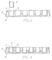
- FIG. 2 shows a cross-sectional view of a multi-well sample plate, taken along line II-II in Fig. 1.
- the walls 12 of the sample wells 11 are made of translucent material and joined together with ribs 13. It is therefore impossible to isolate the wells 11 optically by placing the sample plate 10 on a rigid plate holder made of photon attenuating material and having holes for the wells of the sample plate. Consequently, some amount of the scintillation photons produced by the absorption of the beta particle in sample well 11 may travel to other sample wells and thus produce an undesired increase in background count rates in those wells. This phenomenon is called optical crosstalk.
- FIG. 1 and 2 is shown also a tube 14 made of light impermeable but reflective or scattering material.
- the outer diameter of the tube 14 is equal to or slightly smaller than the inner diameter of sample wells 11 and the shape of the tube 14 corresponds to the shape of the wells 11. For example, if wells 11 are slightly conical, then the shape of the tube 14 is also conical.
- the height of the tube 14 is equal to the inner height of the wells 11.
- the tube can be constructed in many ways. For instance, it can be made of reflective metal, such as polished aluminium. It can also be made of special-grade scattering polycarbonate plastic, such as Lexan (Trade Mark of General Electric) ML 3042 which contains a high amount of white pigment producing a very high degree of reflectivity to eliminate optical crosstalk between wells.
- Reflector metal such as polished aluminium.
- It can also be made of special-grade scattering polycarbonate plastic, such as Lexan (Trade Mark of General Electric) ML 3042 which contains a high amount of white pigment producing a very high degree of reflectivity to eliminate optical crosstalk between wells.
- the plastic should be non-soluble to the liquid scintillator used.
- the tube can be made of plastic having a reflective or scattering surface layer applied to the interior surface of the tube.
- FIG. 3 and FIG. 4 show the sample plate 10 as in FIG. 1 and FIG. 2, except that the wells 11 are provided with tubes 14. Consequently, the sample wells 11 are optically separated. Additionally, the inner surfaces of the tubes 14 guide the scintillation photons produced by the samples in the sample wells 11 to the cathodes of the photomultiplier tubes (not shown), operating in coincidence, which are situated on opposite sides of the sample wells 11.
Abstract
A method of prevent optical crosstalk between different samples in a process of counting liquid scintillation samples deposited in a sample plate, the sample plate, comprising a plurality of sample wells, is described. The sample wells are provided with tubes made of material which is impermeable to, but reflective or scattering for, scintillation light generated by the samples, so that crosstalk is reduced or eliminated.
Description
- Liquid scintillation counters are commonly used for measuring count rates or activities of radioactive samples containing beta, or corresponding, particle emitting radionuclides, e.g. H-3, C-14, S-35, I-125, P-32 etc.
- Many beta particles are of low energy and have ranges generally less than a few tens of micrometers in the sample. As a consequence, the sample to be measured has to be intimately in context with a scintillation medium, most often by dissolving it into a liquid scintillator which typically comprises an organic solvent and at least one fluorescent solute present in a few percent by weight of the solution. In radiation interaction processes, kinetic energy of the beta particle is absorbed by the solvent and then transferred to the solute which is excited to emit scintillation photons in an amount proportional to the energy of the beta particle. These scintillation photons are detected with a detector that usually consists of two, in coincidence operating, photomultiplier tubes producing electrical pulses. The height of the pulses are proportional to the amount of emitted scintillation photons and thus proportional to the energy of the interacted beta particle. Coincident operation is employed for eliminating the random thermal noise pulses of photomultiplier tubes.
- Normally liquid scintillation counters are provided with one detector and they are designed to measure samples in 7 ml or 20 ml glass or plastic vials.
- A novel liquid scintillation counter, designed for counting samples directly from multi-well sample plates, is shown in US Patent no. 5061853 (Lehtinen et al.). This apparatus can count liquid scintillation or corresponding samples directly from a sample plate which comprises several separate sample wells or vials. The apparatus has one or several detectors in order to count one or several samples at a time. The sample plate is placed in the counting position on a rigid plate holder made of photon attenuating material and having holes for the wells of the sample plate. The walls of the holes are reflecting or scattering in order to guide the photons from the liquid scintillation sample to the detectors, consisting of two photomultiplier tubes operating in coincidence and situated on the opposite sides of the holes of the plate holder. The wells of the sample plate can be closed by an adhesive transparent tape. The apparatus can be used also for counting gamma radiation emitting samples if the holes of the sample plate are surrounded by gamma radiation sensitive detectors.
- Another novel scintillation counting system, for the in-situ measurement of radioactive samples in a multiple-well plate, is presented under European Patent Publication Number 0425767A1 (VanCauter et al.). This apparatus is provided, with multiple photomultiplier tubes positioned adjacent to the sample wells containing the scintillator, for simultaneously measuring the radioactivity of multiple samples with only a single photomultiplier tube sensing the scintillations from each well and converting the sensed scintillations into corresponding electrical pulses. The electrical pulses from each photomultiplier tube are processed to discriminate between pulses attributable to sample events within the wells and pulses attributable to non-sample events, such as photomultiplier tube noise. The discrimination is effected by determining whether a selected number of electrical pulses occurs within a prescribed time interval, the occurrence of the selected number of pulses within the prescribed time interval signifying a sample event. Only the electrical pulses attributable to sample events are supplied to a pulse analyzer.
- The multi-well sample plates have typically eight rows of wells, whose diameter is 7 - 8 mm, arranged in twelve columns with 9 millimetres distance between the center points of the wells. The typical volumes of sample wells of such 96-well sample plates are 200 - 400 microlitres, depending on the height of the plate. Another type of multi-well sample plate has four rows of wells arranged in six columns. The volume of the wells of such 24-well sample plates exceeds one millimetre. When the wells of the multi-well sample plate are separate, the plate can be placed for counting on a rigid sample plate holder made of photon attenuating material and having holes for the wells of the sample plate, as shown in US Patent no. 5061853 (Lehtinen et at.). As a consequence, an optically isolated compartment is formed around each sample well of the sample plate. Unfortunately, most of the commercially available multi-well sample plates are transparent and the wells are joined together with ribs, bridges or similar, in order to stiffen the sample plate. Therefore, it is impossible to place them in the above mentioned sample plate holder to isolate them optically. Consequently, some amount of the scintillation photons produced by the absorption of the beta particle in a certain sample well may travel to other sample wells and thus produce an undesired increase in observed count rates in those wells. This phenomenon is called optical crosstalk. It is known that the use of opaque multi-well sample plates can reduce optical crosstalk, as mentioned in TopCount Topics PAN0005 6/91, published by Packard Instrument Company, Meriden USA 1991. However, in many applications transparent multi-well sample plates are preferred, and most of the commercially available multi-well sample plates are transparent.
- The present invention shows a novel method for preventing optical crosstalk between different samples, when measuring liquid scintillation samples deposited in a sample plate comprising a plurality of sample wells.
- According to the invention, it is characterized by providing the sample wells with tubes made of material which is impermeable to, but reflective or scattering for scintillation light generated by the samples.
- FIG. 1
- shows a perspective view of a typical multi-well translucent sample plate having 24 sample wells in 4 x 6 matrix format.
- FIG. 2
- shows a cross-sectional view of a multi-well sample plate having 24 sample wells in 4 x 6 matrix format, taken along line II-II in Fig. 1.
- FIG. 3
- shows a perspective view of a typical multi-well translucent sample plate having 24 sample wells in 4 x 6 matrix format. In this plate each well is provided with a light impermeable but reflective tube.
- FIG. 4
- shows a cross-sectional view of a multi-well sample plate having 24 sample wells in 4 x 6 matrix format taken along line IV-IV in Fig. 3.
- Fig. 1 shows a
multi-well sample plate 10 having 24sample wells 11 in 4 x 6 matrix format. FIG. 2 shows a cross-sectional view of a multi-well sample plate, taken along line II-II in Fig. 1. Thewalls 12 of thesample wells 11 are made of translucent material and joined together withribs 13. It is therefore impossible to isolate thewells 11 optically by placing thesample plate 10 on a rigid plate holder made of photon attenuating material and having holes for the wells of the sample plate. Consequently, some amount of the scintillation photons produced by the absorption of the beta particle in sample well 11 may travel to other sample wells and thus produce an undesired increase in background count rates in those wells. This phenomenon is called optical crosstalk. - In FIG. 1 and 2 is shown also a
tube 14 made of light impermeable but reflective or scattering material. The outer diameter of thetube 14 is equal to or slightly smaller than the inner diameter ofsample wells 11 and the shape of thetube 14 corresponds to the shape of thewells 11. For example, ifwells 11 are slightly conical, then the shape of thetube 14 is also conical. The height of thetube 14 is equal to the inner height of thewells 11. - The tube, according to the invention, can be constructed in many ways. For instance, it can be made of reflective metal, such as polished aluminium. It can also be made of special-grade scattering polycarbonate plastic, such as Lexan (Trade Mark of General Electric) ML 3042 which contains a high amount of white pigment producing a very high degree of reflectivity to eliminate optical crosstalk between wells.
- Ideally, the plastic should be non-soluble to the liquid scintillator used. Furthermore, the tube can be made of plastic having a reflective or scattering surface layer applied to the interior surface of the tube.
- FIG. 3 and FIG. 4 show the
sample plate 10 as in FIG. 1 and FIG. 2, except that thewells 11 are provided withtubes 14. Consequently, thesample wells 11 are optically separated. Additionally, the inner surfaces of thetubes 14 guide the scintillation photons produced by the samples in thesample wells 11 to the cathodes of the photomultiplier tubes (not shown), operating in coincidence, which are situated on opposite sides of thesample wells 11.
Claims (4)
- A scintillation sample plate (10) comprising a moulded plastics tray having an array of sample wells (11) moulded in it and being moulded from a material transparent or translucent to the scintillation light, characterized in that the interior of each sample well is lined at its sides but not its base with a material (14) having reflective or scattering properties for the scintillation light.
- A scintillation sample plate according to Claim 1, wherein the sample wells are each lined with a tube (14) formed of reflective or scattering material and substantially covering the entire side walls of the sample wells.
- A device for preventing optical crosstalk between different samples in a process of counting liquid scintillation samples deposited in a sample plate, the sample plate comprising a plurality of sample wells, characterized in that the device is a tube made of material which is impermeable to, but reflective or scattering for, scintillation light generated by the samples.
- A method for preventing optical crosstalk between different samples in a process of counting liquid scintillation samples deposited in a sample plate, the sample plate comprising a plurality of sample wells, characterized by lining the internal walls of the sample wells with tubes made of material which is impermeable to, but reflective or scattering for, scintillation light generated by the samples.
Applications Claiming Priority (2)
| Application Number | Priority Date | Filing Date | Title |
|---|---|---|---|
| US948603 | 1992-09-23 | ||
| US07/948,603 US5329123A (en) | 1992-09-23 | 1992-09-23 | Method and a device for preventing optical crosstalk between liquid scintillation samples deposited on transculcent sample plates |
Publications (2)
| Publication Number | Publication Date |
|---|---|
| EP0589691A2 true EP0589691A2 (en) | 1994-03-30 |
| EP0589691A3 EP0589691A3 (en) | 1995-12-06 |
Family
ID=25488042
Family Applications (1)
| Application Number | Title | Priority Date | Filing Date |
|---|---|---|---|
| EP93307530A Withdrawn EP0589691A3 (en) | 1992-09-23 | 1993-09-23 | Preventing optical crosstalk between liquid scintillation samples in translucent sample plates |
Country Status (2)
| Country | Link |
|---|---|
| US (1) | US5329123A (en) |
| EP (1) | EP0589691A3 (en) |
Cited By (6)
| Publication number | Priority date | Publication date | Assignee | Title |
|---|---|---|---|---|
| WO1994021379A1 (en) * | 1993-03-16 | 1994-09-29 | Westaim Technologies Inc. | Enhanced microtitre plate and immunoassays conducted therein |
| EP0816827A2 (en) * | 1996-06-24 | 1998-01-07 | Schweizerische Eidgenossenschaft vertreten durch das AC-Laboratorium Spiez der Gruppe für Rüstungsdienste | A multiwell arrangement for instrumental analysis |
| EP0963790A2 (en) * | 1998-06-09 | 1999-12-15 | Peter J. Krauser | Microtitration plate |
| WO2002007873A2 (en) * | 2000-07-19 | 2002-01-31 | Uop Llc | Multiautoclave with liner for combinatorial synthesis of zeolites and other materials |
| AT510898B1 (en) * | 2007-12-21 | 2014-11-15 | Medizinische Universität Graz | MENISKUS EQUILIBRATION SYSTEM FOR A MICROTITER PLATE |
| CN111337969A (en) * | 2018-12-19 | 2020-06-26 | 同方威视技术股份有限公司 | Preparation method of scintillator reflecting layer |
Families Citing this family (10)
| Publication number | Priority date | Publication date | Assignee | Title |
|---|---|---|---|---|
| US6057163A (en) * | 1998-04-28 | 2000-05-02 | Turner Designs | Luminescence and fluorescence quantitation system |
| JP2004191127A (en) * | 2002-12-10 | 2004-07-08 | Nippon Sheet Glass Co Ltd | Biochemical vessel |
| US20050287573A1 (en) * | 2004-06-18 | 2005-12-29 | North Dakota State University | Lined multi-well plates |
| US7505238B2 (en) * | 2005-01-07 | 2009-03-17 | Agnes Neves Woo | ESD configuration for low parasitic capacitance I/O |
| CN105277965B (en) * | 2015-09-30 | 2017-12-12 | 华中科技大学 | A kind of detector for being used to launch imaging device |
| USD826425S1 (en) * | 2016-10-17 | 2018-08-21 | Becton, Dickinson And Company | Tube tray |
| USD825775S1 (en) * | 2016-10-17 | 2018-08-14 | Becton, Dickinson And Company | Tube tray |
| USD826426S1 (en) * | 2016-10-17 | 2018-08-21 | Becton, Dickinson And Company | Tube tray |
| USD825076S1 (en) * | 2016-11-23 | 2018-08-07 | Clifford L. Librach | Tissue culture dish |
| JP1689807S (en) * | 2020-12-25 | 2021-07-12 | Culture container |
Citations (3)
| Publication number | Priority date | Publication date | Assignee | Title |
|---|---|---|---|---|
| JPS5892979A (en) * | 1981-11-30 | 1983-06-02 | Toshiba Corp | Radiation detector |
| GB2167279A (en) * | 1984-11-15 | 1986-05-21 | Ian Redmayne | Radiation imaging |
| WO1989012838A1 (en) * | 1988-06-17 | 1989-12-28 | Wallac Oy | Sample plate liquid scintillation counter |
Family Cites Families (1)
| Publication number | Priority date | Publication date | Assignee | Title |
|---|---|---|---|---|
| SE8803115D0 (en) * | 1988-09-06 | 1988-09-06 | Wallac Oy | APPARATUS FOR MONITORING THE RADIOACTIVITY OF A PLURALITY OF LIQUID SCINTILLATION SAMPLES DEPOSITED ON MULTI-WELL SAMPLE PLATES |
-
1992
- 1992-09-23 US US07/948,603 patent/US5329123A/en not_active Expired - Lifetime
-
1993
- 1993-09-23 EP EP93307530A patent/EP0589691A3/en not_active Withdrawn
Patent Citations (3)
| Publication number | Priority date | Publication date | Assignee | Title |
|---|---|---|---|---|
| JPS5892979A (en) * | 1981-11-30 | 1983-06-02 | Toshiba Corp | Radiation detector |
| GB2167279A (en) * | 1984-11-15 | 1986-05-21 | Ian Redmayne | Radiation imaging |
| WO1989012838A1 (en) * | 1988-06-17 | 1989-12-28 | Wallac Oy | Sample plate liquid scintillation counter |
Non-Patent Citations (1)
| Title |
|---|
| PATENT ABSTRACTS OF JAPAN vol. 007 no. 196 (P-219) ,26 August 1983 & JP-A-58 092979 (TOKYO SHIBAURA DENKI KK) 2 June 1983, * |
Cited By (9)
| Publication number | Priority date | Publication date | Assignee | Title |
|---|---|---|---|---|
| WO1994021379A1 (en) * | 1993-03-16 | 1994-09-29 | Westaim Technologies Inc. | Enhanced microtitre plate and immunoassays conducted therein |
| EP0816827A2 (en) * | 1996-06-24 | 1998-01-07 | Schweizerische Eidgenossenschaft vertreten durch das AC-Laboratorium Spiez der Gruppe für Rüstungsdienste | A multiwell arrangement for instrumental analysis |
| EP0816827A3 (en) * | 1996-06-24 | 1998-06-03 | Schweizerische Eidgenossenschaft vertreten durch das AC-Laboratorium Spiez der Gruppe für Rüstungsdienste | A multiwell arrangement for instrumental analysis |
| EP0963790A2 (en) * | 1998-06-09 | 1999-12-15 | Peter J. Krauser | Microtitration plate |
| EP0963790A3 (en) * | 1998-06-09 | 2000-08-16 | Peter J. Krauser | Microtitration plate |
| WO2002007873A2 (en) * | 2000-07-19 | 2002-01-31 | Uop Llc | Multiautoclave with liner for combinatorial synthesis of zeolites and other materials |
| WO2002007873A3 (en) * | 2000-07-19 | 2002-06-13 | Uop Llc | Multiautoclave with liner for combinatorial synthesis of zeolites and other materials |
| AT510898B1 (en) * | 2007-12-21 | 2014-11-15 | Medizinische Universität Graz | MENISKUS EQUILIBRATION SYSTEM FOR A MICROTITER PLATE |
| CN111337969A (en) * | 2018-12-19 | 2020-06-26 | 同方威视技术股份有限公司 | Preparation method of scintillator reflecting layer |
Also Published As
| Publication number | Publication date |
|---|---|
| EP0589691A3 (en) | 1995-12-06 |
| US5329123A (en) | 1994-07-12 |
Similar Documents
| Publication | Publication Date | Title |
|---|---|---|
| US5329123A (en) | Method and a device for preventing optical crosstalk between liquid scintillation samples deposited on transculcent sample plates | |
| US5298753A (en) | Arrangement for counting liquid scintillation samples on bottom-window multi-well sample plates | |
| US5317158A (en) | Unitary scintillation detector and system | |
| US5198670A (en) | Scintillation counting system for in-situ measurement of radioactive samples in a multiple-well plate | |
| US5294795A (en) | Arrangement for counting liquid scintillation samples on multi-well filtration plates | |
| US5391878A (en) | Multiplexed fiber readout of scintillator arrays | |
| EP0380613B1 (en) | Sample plate liquid scintillation counter | |
| US3898463A (en) | Scintillation counting apparatus | |
| US5289510A (en) | Two-dimensional position sensitive radiation detectors | |
| EP0490108B1 (en) | Method, apparatus and applications of the quantitation of multiple gamma-photon producing isotopes with increased sensitivity | |
| US5146093A (en) | Liquid scintillation measurement system with active guard shield | |
| WO2002088773A1 (en) | Gamma-ray detection apparatus and method for positron emission tomography | |
| EP0327588B1 (en) | High sensitivity optical imaging apparatus | |
| JPH05341047A (en) | Effective method for simultaneous measuring of alpha and beta@(3757/24)gamma) ray and associate sensor | |
| EP0334528B1 (en) | Improved liquid scintillation measurement system with active guard shield | |
| US4495420A (en) | Multilayer scintillation chamber for the simultaneous measurement of radioactive samples | |
| EP0396657B1 (en) | An apparatus for monitoring the radioactivity of a plurality of liquid scintillation samples deposited on multi-well sample plates | |
| US5144136A (en) | Device for simultaneously measuring particle or quantum beams from many samples at once | |
| US5180916A (en) | Apparatus for detecting ionizing radiation | |
| CN115236720A (en) | Multiple type of ray detection device | |
| EP0589689A2 (en) | A method of producing standardization samples for obtaining a liquid scintillation counting quench curve and a foil | |
| US3835325A (en) | Radiation detectors using multiple scintillation crystal pieces | |
| WO1990005922A1 (en) | Radiation scintillation detector | |
| Brownell et al. | Large Plastic Scintillators for Radioactivity Measurement | |
| Hennig et al. | Digital pulse shape analysis with phoswich detectors to simplify coincidence measurements of radioactive xenon |
Legal Events
| Date | Code | Title | Description |
|---|---|---|---|
| PUAI | Public reference made under article 153(3) epc to a published international application that has entered the european phase |
Free format text: ORIGINAL CODE: 0009012 |
|
| AK | Designated contracting states |
Kind code of ref document: A2 Designated state(s): DE FR GB |
|
| PUAL | Search report despatched |
Free format text: ORIGINAL CODE: 0009013 |
|
| AK | Designated contracting states |
Kind code of ref document: A3 Designated state(s): DE FR GB |
|
| STAA | Information on the status of an ep patent application or granted ep patent |
Free format text: STATUS: THE APPLICATION IS DEEMED TO BE WITHDRAWN |
|
| 18D | Application deemed to be withdrawn |
Effective date: 19951001 |