EP0588868B1 - Wrist mount apparatus for use in blood pressure tonometry - Google Patents
Wrist mount apparatus for use in blood pressure tonometry Download PDFInfo
- Publication number
- EP0588868B1 EP0588868B1 EP92911835A EP92911835A EP0588868B1 EP 0588868 B1 EP0588868 B1 EP 0588868B1 EP 92911835 A EP92911835 A EP 92911835A EP 92911835 A EP92911835 A EP 92911835A EP 0588868 B1 EP0588868 B1 EP 0588868B1
- Authority
- EP
- European Patent Office
- Prior art keywords
- transducer
- wrist
- platform
- base portion
- artery
- Prior art date
- Legal status (The legal status is an assumption and is not a legal conclusion. Google has not performed a legal analysis and makes no representation as to the accuracy of the status listed.)
- Expired - Lifetime
Links
- 210000000707 wrist Anatomy 0.000 title claims abstract description 151
- 230000036772 blood pressure Effects 0.000 title abstract description 20
- 210000001367 artery Anatomy 0.000 claims abstract description 58
- 230000008878 coupling Effects 0.000 claims description 62
- 238000010168 coupling process Methods 0.000 claims description 62
- 238000005859 coupling reaction Methods 0.000 claims description 62
- 238000006073 displacement reaction Methods 0.000 claims description 21
- 239000000356 contaminant Substances 0.000 abstract description 5
- 238000001361 intraarterial administration Methods 0.000 abstract description 4
- 239000000463 material Substances 0.000 abstract description 2
- 238000000034 method Methods 0.000 description 21
- 230000036961 partial effect Effects 0.000 description 12
- 230000007246 mechanism Effects 0.000 description 11
- 230000008901 benefit Effects 0.000 description 9
- 230000000994 depressogenic effect Effects 0.000 description 8
- 210000002321 radial artery Anatomy 0.000 description 7
- 239000010408 film Substances 0.000 description 6
- 238000009530 blood pressure measurement Methods 0.000 description 4
- 238000005259 measurement Methods 0.000 description 4
- 230000000452 restraining effect Effects 0.000 description 4
- 238000000926 separation method Methods 0.000 description 4
- 230000009471 action Effects 0.000 description 3
- 238000013459 approach Methods 0.000 description 3
- 230000006835 compression Effects 0.000 description 3
- 238000007906 compression Methods 0.000 description 3
- 230000000670 limiting effect Effects 0.000 description 3
- 230000007257 malfunction Effects 0.000 description 3
- 238000012544 monitoring process Methods 0.000 description 3
- 230000017531 blood circulation Effects 0.000 description 2
- 238000011109 contamination Methods 0.000 description 2
- 238000013461 design Methods 0.000 description 2
- 230000035487 diastolic blood pressure Effects 0.000 description 2
- 230000013011 mating Effects 0.000 description 2
- 238000002559 palpation Methods 0.000 description 2
- 230000035488 systolic blood pressure Effects 0.000 description 2
- 239000010409 thin film Substances 0.000 description 2
- 238000012546 transfer Methods 0.000 description 2
- 208000031104 Arterial Occlusive disease Diseases 0.000 description 1
- 230000001944 accentuation Effects 0.000 description 1
- 239000000853 adhesive Substances 0.000 description 1
- 230000001070 adhesive effect Effects 0.000 description 1
- 208000021328 arterial occlusion Diseases 0.000 description 1
- 238000010276 construction Methods 0.000 description 1
- 230000006378 damage Effects 0.000 description 1
- 230000000881 depressing effect Effects 0.000 description 1
- 238000003745 diagnosis Methods 0.000 description 1
- 230000003205 diastolic effect Effects 0.000 description 1
- 230000009977 dual effect Effects 0.000 description 1
- 230000000694 effects Effects 0.000 description 1
- 229920001971 elastomer Polymers 0.000 description 1
- 239000000806 elastomer Substances 0.000 description 1
- 239000012530 fluid Substances 0.000 description 1
- 208000015181 infectious disease Diseases 0.000 description 1
- 238000011835 investigation Methods 0.000 description 1
- 239000000203 mixture Substances 0.000 description 1
- 230000000135 prohibitive effect Effects 0.000 description 1
- 238000009877 rendering Methods 0.000 description 1
- 230000000717 retained effect Effects 0.000 description 1
- 238000005096 rolling process Methods 0.000 description 1
- 230000006641 stabilisation Effects 0.000 description 1
- 238000011105 stabilization Methods 0.000 description 1
- 238000001356 surgical procedure Methods 0.000 description 1
- 230000000451 tissue damage Effects 0.000 description 1
- 231100000827 tissue damage Toxicity 0.000 description 1
Images




Classifications
-
- A—HUMAN NECESSITIES
- A61—MEDICAL OR VETERINARY SCIENCE; HYGIENE
- A61B—DIAGNOSIS; SURGERY; IDENTIFICATION
- A61B5/00—Measuring for diagnostic purposes; Identification of persons
- A61B5/02—Detecting, measuring or recording for evaluating the cardiovascular system, e.g. pulse, heart rate, blood pressure or blood flow
- A61B5/021—Measuring pressure in heart or blood vessels
Definitions
- the invention relates to a wrist mount apparatus for mounting a tissue stress sensor on either wrist of a wearer, for use in blood pressure tonometry, in accordance with the preamble of claim 1.
- a wrist mount apparatus of this kind is known from EP-A-333442.
- Systems for measuring the intra-arterial blood pressure of a patient can be subdivided into two main groups--those which invade the arterial wail to access blood pressure and those which use noninvasive techniques. Initially, the most accurate blood pressure measurements were achievable only by way of invasive methods.
- One common invasive method involves inserting a fluid filled catheter into the patient's artery.
- invasive methods provide for accurate blood pressure measurements, the associated risk of infection and potential for complications, in many cases, outweigh the advantages in using invasive methods. Because of these risks associated with invasive methods, a noninvasive method, known as the Korotkoff method is widely used.
- the Korotkoff method is known as an auscultatory method because it uses the characteristic sound made as the blood flows through the artery to mark the points of highest (systolic) and lowest (diastolic) blood pressure.
- the Korotkoff method is noninvasive, it only provides a measurement of the highest pressure and the lowest pressure along the continuous pressure wave. While systolic and diastolic pressure are sufficient for accurate diagnosis in many instances, there are many applications in which it is desirable to monitor and utilize the entire characteristic curve of the blood pressure wave. In these applications, the Korotkoff method simply is incapable of providing ample information.
- it necessitates the temporary occlusion of the artery in which blood pressure is being monitored. While arterial occlusion is not prohibitive in many applications, there are occasions where the patient's blood pressure must be monitored continuously (such as when undergoing surgery) and accordingly, the prohibiting of blood flow, even on a temporary basis, is undesirable.
- a blood pressure measuring apparatus having a housing detachably set on a body surface of a subject.
- a pressure sensor is accommodated in the housing such that the pressure sensor is opposed to the body surface when the housing is set on the body surface, the pressure sensor being pressed against the body surface so as to detect pulse waves produced from an arterial vessel of the subject.
- a pressurization system for continuous blood pressure monitoring comprising a dual chamber compression apparatus and switching mechanism, both of which are engaged to a servo motor drive mechanism. The drive mechanism simultaneously controls the compression apparatus and the switching mechanism thereby coordinating flow of air from the compression chamber to the pressurizable chamber within the transducer.
- EP-A-333442 discloses a pulse wave detecting apparatus for measuring blood pressure comprising a pressure sensor mounted within a housing that is attached to a patient's wrist by a band.
- the band includes a plurality of pivotable members which assist in maintaining the housing in a stable position on the wrist during blood pressure measurement to improve the accuracy of the measurement.
- the above systems are designed to be universally applicable for either right or left wrist usage. Because they are designed with this universality in mind, they are unable to take advantage of specific wrist characteristics when, properly taken advantage of, can provide a more stable platform to thereby engage and operate the tissue stress transducer.
- a wrist mount apparatus for use in blood pressure tonometry wherein various wrist characteristics are taken advantage of to provide a single sensor which can universally adapt to the right or left wrist and accordingly, provide a secure platform to thereby mount a tissue stress sensor upon.
- a wrist mount apparatus in accordance with claim 1. Preferred embodiments are set forth in the further claims 2 to 11.
- the wrist mount apparatus places a tissue stress transducer in operative engagement with the tissue overlying an artery of interest.
- the wrist mount apparatus comprises a base portion which is adapted to be mounted to the wrist of a wearer and a transducer platform adapted to house the tissue stress transducer.
- the transducer platform is pivotally and slidably mounted to the base portion such that when the wrist mount apparatus is mounted to the right wrist of the wearer, the transducer platform can be slid into a use position and is thereby operative for allowing the transducer platform to be pivoted into operative engagement with the tissue overlying an artery of interest.
- the transducer platform is slidable to a second position wherein it allows the tissue. stress transducer to pivot into operative engagement with the tissue overlaying an artery of interest, whereby the apparatus is adapted for use on the right or left wrist of the wearer.
- the base portion includes first and second window portions, whereby the first window portion is placed over the artery of interest when the apparatus is placed on the right wrist of the wearer and the second window is placed over the artery of interest when the apparatus is placed on the left wrist of the wearer.
- the window portions are preferably large enough to permit the finger of an operator to pass therethrough for the purpose of palpating the artery of interest.
- the wrist mount apparatus preferably includes locking means for locking the base portion to the transducer platform thereby preventing the platform from freely pivoting when the apparatus is in use. Release means are provided to release the transducer platform from the lock position when it is desirable to move the tissue stress sensor to a different position or to manually palpate the artery of interest to ensure that the wrist mount apparatus is properly positioned on the wearer's wrist.
- the base portion of the mounting apparatus has a wrist engaging surface wherein the wrist engaging surface is generally concave to generally conform the base to the natural curvature of the wearers wrist. This promotes general wearer comfort as well as stability of the base on the wearer's wrist. Additionally, the concave surface tends to stabilize the artery of interest against moving or rolling. Thus, the artery of interest is stabilized and has less of a tendency to move once pressure is applied to it by the tissue stress sensor than it otherwise would in applications where the wrist engaging surface of the base portion is flat or non-concave. Additional stability is also provided by virtue of a rib disposed between adjacent windows.
- a third position is provided whereby the tissue stress sensor is pivotal away from the base portion in sufficient displacement so as to make the tissue stress sensor accessible for calibration without necessitating its removal from the apparatus.
- the third position is also effective for making sensor easier to service or remove.
- the apparatus of the present invention sets forth a wrist mount apparatus comprising a base portion adapted to be mounted to the wrist of a wearer, a transducer platform adapted to house the tissue stress transducer, wherein the transducer platform is movably engaged to the base portion, means coupled between the transducer platform and the tissue stress transducer for placing the tissue stress transducer into operative engagement with the tissue overlying the artery of interest, and means, coupled between the base portion and the transducer platform, for releasing the tissue stress transducer from operative engagement with the tissue overlying the artery of interest.
- the releasing means is operative whenever the force of the tissue stress transducer against the tissue of the wearer exceeds a predetermined value.
- the releasing means preferably includes a resilient engaging finger extending from the transducer platform wherein the finger is adapted to engage an engaging surface on the base portion thereby retaining the transducer platform to the base portion and preventing, under normal operating conditions, any relative movement between the base portion and the transducer platform.
- the resilient engaging finger is sufficiently distorted to disengage from the engaging surface of the base portion thereby allowing relative movement to take place between the base portion and the transducer platform.
- the resilient engaging finger preferably includes a concave engagement surface and of the engagement surface of the base portion is preferably generally concave.
- the apparatus of the present invention provides a wrist mount apparatus comprising a base portion adapted to be mounted to the wrist of a wearer, a transducer platform adapted to engage a tissue stress transducer, and a quick disconnect means for connecting the transducer platform to the base portion whereby the disconnect means allows the transducer platform and the tissue stress sensor to be quickly removed from the base portion.
- the quick disconnect means preferably includes a coupling member fastened to the base portion wherein the coupling member includes a lip portion and the transducer platform includes a recess portion wherein the lip portion is adapted to slidingly engage and retain the recessed portion.
- the wrist mount apparatus of the present invention includes a base portion adapted to be mounted to the wrist of a wearer and a transducer platform adapted to house the tissue stress transducer, wherein the transducer platform is engaged to the base portion.
- Means are disposed between the tissue stress sensor and the tissue overlying an artery of interest for preventing direct contact between the tissue stress sensor and the tissue whereby the sensor face is not contaminated by elements disposed on the tissue of the wearer.
- preventing means includes a thin film of plastic.
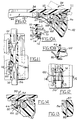
- Figure 1 is a perspective view of the wrist mount apparatus of the present invention as it is oriented on a wearers wrist.
- Figure 2 is a perspective view of the wrist mount apparatus of the present invention wherein the wearers artery of interest is being palpated.
- Figure 3 is a perspective view of the wrist mount apparatus of the present invention wherein the transducer platform has been slid in position adjacent the artery of interest.
- Figure 4 is a perspective view of the wrist mount apparatus of the present invention wherein the transducer platform has been rotated and locked in position over an artery of interest.
- Figure 5A is a perspective exploded top view of the wrist mount apparatus of the present invention.
- Figure 5B is a perspective exploded bottom view of the wrist mount apparatus of the present invention.
- Figure 6 is a top view of the wrist mount apparatus of the present invention.
- Figure 7 is a rear side view of the wrist mount apparatus of the present invention taken substantially along lines 7-7 of Figure 6.
- Figure 8 is a partial cross-sectional view of a wrist mount apparatus of the present invention taken substantially along lines 8-8 of Figure 6.
- Figure 9 is a partial bottom view of the wrist mount apparatus of the present invention taken substantially along lines 9-9 of Figure 8.
- Figure 10 is a partial cross-sectional view of the wrist mount apparatus of the present invention taken substantially along lines 10-10 of Figure 6.
- Figure 10A is a partial enlarged view of the overload release mechanism of the present invention shown in an underloaded, or normal use, position.
- Figure 10B is a partial cross-sectional view of the overload finger of the present invention shown in an overloaded position.
- FIG 11 is a partial cross-sectional view of the wrist mount apparatus of the present invention taken substantially along lines 11-11 of Figure 10.
- Figure 12 is a partial top view of the wrist mount apparatus of the present invention wherein the manual release button is engaged.
- Figure 13 is a partial cross-section of the mechanical release button of the present invention taken substantially along lines 13-13 of Figure 12.
- Figure 14 is a partial cross-sectional view of the mechanical release button of the present invention taken substantially along lines 14-14 of Figure 12.
- Figure 15 is a partial cross-sectional view of the wrist mount apparatus of the present invention showing the slidable engagement between the transducer platform and the coupling member.
- Figure 16 is a cross-sectional view of the wrist mount apparatus of the present invention showing the transducer platform separated from the coupling member.
- Figure 17 is a top view of the coupling member taken substantially along lines 17-17 of Figure 16.
- Figure 18 is a bottom view of the transducer platform taken substantially along lines 18-18 of Figure 16.
- Figure 19 is a front side view of the wrist mount apparatus of the present invention taken substantially along lines 19-19 of Figure 6.
- Figure 20 is a partial right side view of the wrist mount apparatus of the present invention taken substantially along lines 20-20 of Figure 19.
- Figure 21 is a perspective view of the wrist mount apparatus of the present invention shown placed on the left hand wrist of a wearer.
- Figure 22 is a bottom perspective view of the transducer platform.
- Figure 23 is a partial perspective bottom view of the transducer platform of Figure 22.
- Figure 24 is a perspective view of the coupling member.
- Figure 25 is a top view of a second embodiment of the wrist mount apparatus of the present invention shown with its transducer platform in a first position.
- Figure 26 is the second embodiment of the wrist mount apparatus of the present invention shown with its transducer platform pivoted out of the first position and into a second position.
- Figure 27 is a cross-sectional view of the second embodiment of the wrist mount apparatus of the present invention with its sensor head fully retracted.
- Figure 28 is a cross-sectional view of the second embodiment of the wrist mount apparatus of the present invention shown with its sensor head in an intermediate position.
- Figure 29 is a cross-sectional view of the second embodiment of the wrist mount apparatus of the present invention shown with its sensor head in a fully extended position.
- wrist mount apparatus 30 generally comprises base portion 32 and transducer platform 34.
- Transducer platform is attached to base portion 32 in a way which allows platform 34 to move laterally 36 and pivotally 38.
- Base portion 32 includes restraining strap 40 for fixing base portion 32 to the wrist area 42 of a user.
- Base portion 32 includes first and second window 44, 46.
- wrist mount apparatus 30 of the present invention is well suited to be used on either the right wrist or the left wrist of a wearer.
- sensor 48 is a tissue contact stress sensor as disclosed in US-A-5 154 680
- the wrist apparatus of the present invention is capable of employing any sensor suitable for use in blood pressure tonometry. Accordingly, it is to be understood that although the use of tissue contact stress sensor, or tissue stress sensor is employed throughout this description, the wrist mount apparatus of the present invention is adapted to be used with any suitably designed sensor.
- transducer platform 34 is moved laterally 36 such that first window 44 is generally unobstructed.
- base portion 32 is placed on wrist 42 of the wearer such that first window 44 is generally centered upon the tissue overlaying the artery of interest.
- restraining strap 40 is placed around the wrist thereby securing base portion 32 to wrist area 42.
- the artery of interest is palpated 52 to ensure that the artery of interest properly lies within the area framed by first window 44. If no arterial pulse can be detected therein, strap 40 is released and window 44 is moved to a new location wherein palpation is attempted once more.
- platform 34 is moved laterally 36 such that tissue stress sensor 48 is generally above first window 44. Once this lateral movement 36 has been accomplished, platform 34 is pivoted 38 towards tissue 50 until platform 34 locks into its use position. Once this lateral 36 and pivotal 38 movement is accomplished, platform 34 is positioned over base portion 32 in the manner generally depicted in Figure 4. In this position, wrist mount apparatus 30 is operative for use in a system for noninvasively determining the intra-arterial blood pressure of a wearer. Various features of wrist mount apparatus 30 will now be discussed, in detail, in conjunction with the remaining figures.
- base portion 32 is adapted to be fastened to the wrist of a wearer by way of strap 40.
- Strap 40 is fixed, et one end, to base portion 32 by way of strap pin 41.
- strap 40 is fastened to surface 60 of base portion 32 which employs velcro 62, or some other suitable means for retaining strap 40.
- This provides the primary means whereby base portion 32 is firmly secured to the wrist of a wearer thereby providing a secure foundation for mounting the remaining components of wrist mount apparatus 30.
- the relatively wide width 64 of base 32, the curvature of wrist engaging surface 88 of base 32 and its relatively low profile all act to provide an excellent, stable base upon which a tissue stress sensor can operate.
- Transducer platform 34 is adapted to engage, and be retained by, coupling member 54.
- the nature of this engagement is unique to the apparatus of the present invention and will be more fully explained in conjunction with subsequent drawings. However, it is important to note at this juncture, that the nature of the connection between platform 34 and coupling member 54 is one which can quickly be fastened, and unfastened, without using tools thereby making the disclosed system particularly attractive for replacing tissue stress sensors in the field. It also permits the face to remain in place on a wearer's wrist while replacing sensor 48.
- Transducer platform 34 is fitted with a main aperture 33 and secondary apertures 35.
- Secondary apertures 35 provide a means of mounting a tissue stress sensor and its accompanying movement mechanism to transducer platform 34.
- Main aperture 33 provides a passageway whereby tissue stress sensor can pass through platform 34 and operatively engage the tissue overlying an artery of interest.
- Transducer platform 34 mounts to coupling member 54 in a manner which will be more fully discussed hereinafter.
- Coupling retaining pin 55 acts to connect coupling member 54 to base portion 32 in a way which allows coupling member 54 to move both laterally 36 along pin 55 and pivotally 38 about pin 55.
- the lateral movement 36 allows platform 34 to engage either window 44, 46 for either right wrist use or left wrist use respectively.
- Resilient engaging finger 66 extends from a bottom surface 68 of coupling member 54. Resilient engaging finger 66 is adapted to lock transducer platform 34 into its use position by contacting engagement surface 70, 72 when coupling member 54 is in the right hand use position, left hand use position respectively. Along with its engaging function, resilient engaging finger 66 also serves as an overload release member to prevent tissue damage from occurring in the event that the sensor movement mechanism malfunctions and attempts to apply excessive force to the wrist tissue of the wearer. This overload function will be described in greater detail in conjunction with the subsequent drawings.
- Right wrist release button 56 is operative to release engagement finger 66 from engagement surface 70. Accordingly, after it is desired to pivot 38 platform 34 away from window 44 button 56 is depressed towards base portion 32 thereby causing conical surface 74 to engage resilient finger 66 and dislodge it from engagement surface 70 of base portion 32. Thus, it can be seen, that right wrist release button 56 releases transducer platform 34 from its positive engagement with base portion 32 thereby rendering it free to pivot 38.
- Right wrist release button 56 is fitted with a slotted aperture 78 which cooperates with retaining pin 57 to limit the inward and outward travel of button 56.
- Return spring 76 acts to keep right wrist release button 56 outwardly biased thereby urging it to return to its outwardly most bias position whenever a depression force is not placed on it.
- right wrist release button 56 is operative to disengage finger 66 from engagement surface 70 of base portion 32 in the event that button 56 is depressed such that conical surface 74 engages and sufficiently displaces resilient finger 66.
- pin 59 cooperates with slotted aperture 79 of left wrist release button 58 to define its inward and outward allowable travel.
- left wrist release button 58 outwardly biased and conical surface 75 of left wrist release button 58 is adapted to engage finger 66 and displace it from engagement surface 72 of base portion 32 in a way which causes finger 66 to release its positive engagement with surface 72 thereby allowing transducer platform 34 to pivot 38.
- Spring assembly 80 is operative to place a force of upward urging on finger 66 whenever finger 66 is engaged with surface 70 of base portion 32.
- Spring assembly 80 functions to ensure that coupling member 54 is rotated 38 away from engagement surface 70 whenever right wrist release button 56 is depressed. This rotation is generally desirable to ensure that platform 34 positively disengages from its use position whenever sufficient inward force is placed on release button 56. Without the upward biasing provided by spring assembly 80, an inward force on button 56, which is sufficient to disengage resilient finger 66 from engagement surface 70, would not fully release finger 66 from surface 70. This is because no other forces would be present to rotate 38 platform 34 away from window 44 and upon release of button 56, finger 66 would most likely reengage surface 70.
- spring assembly 80 is provided to exert an upward force on finger 66 thereby causing transducer platform to "pop up" whenever right release button 56 is depressed with sufficient force. This pop up action makes it clear that finger 66 has positively disengaged from surface 70.
- a similar spring assembly is utilized on finger 66 when platform 34 is used in its left wrist use position.
- a bottom view of base portion 32 shows spring assembly 81 which is associated with the use of wrist mount apparatus 30 when it is used on the left wrist of a wearer.
- Tension adjustment screw (or spring plunger) 82 is adapted to threadedly engage aperture 84 of base portion 32.
- Tension adjustment screw 82 is fitted with a spring loaded spherical-shaped end 86 which is adapted to frictionally engage barrel 53 of coupling member 54. This is generally desirable because as wrist mount apparatus 30 is used, barrel aperture 51 will begin to wear thereby allowing undesirable movement to take place between coupling member 54 and pin 55. If such wear should take place, the spring (spring not shown) within screw 82 is effective for maintaining an uninterrupted tension against barrel 53.
- tension adjustment screw 82 serves to locate and hold coupling member in the left, center or right hand position. For example, when coupling member 54 is in its central, raised position (see Figure 15), a groove or depression centrally located in barrel 53 (groove or depression not shown) can engage spherical end 86 of screw 82 maintaining coupling member 54 in its central position.
- wrist mount apparatus 30 employs transducer platform 34 in a first use position when apparatus 30 is mounted to the right wrist of a user (see Figure 4) and employs platform 34 in a second use position when apparatus 30 is mounted to the left wrist of a wearer (see Figure 21). Because apparatus 30 must be adaptable to be used on either the right or the left wrist of a wearer, and also because contour 88 of base 32 (see Figure 5B) is adapted to conform to the surface contour of a users wrist, base portion 32 must be flipped around when switched from opposite wrists.
- platform 34 must be movable laterally 36 so that tissue stress sensor 48 can always be placed in the window proximate the wearers fingers.
- base 34 is positioned laterally 36 such that tissue stress sensor 48 is positioned generally above window 44.
- platform 34 is moved laterally 36 such that it generally overlies window 46 (window 46 not visible in Figure 21).
- coupling member 54 is prevented from pivoting beyond angular displacement 90 as shown in Figure 8.
- Angular displacement 90 need only be made large enough to allow finger access to windows 44, 46 thereby permitting an operator to manually palpate an artery of interest to verify the proper positioning of wrist mount apparatus 30. It is thought that by limiting angular displacement 90, sensor 48 will generally not be exposed to inadvertent contact thereby limiting the risk that sensor 48 will be damaged while it is being laterally displaced from its first use position to its second use position.
- the manner in which angular displacement 90 is limited is established by limiting the rotation allowed by rear portion 92 of coupling member 54 (see Figures 7 and 8).
- angular displacement 90 when angular displacement 90 reaches its maximum allowable travel, rear portion 92 of coupling member 54 contacts upper ridge 94 of base portion 32 and is no longer permitted to rotate any further.
- the amount of angular displacement 90 which is necessary is generally determined by the length of resilient engaging finger 66 and the amount of clearance needed to manually palpate the artery of interest through an appropriately positioned window. That is to say, displacement 90 must be sufficient enough to allow coupling member 54 to be slid between first and second use positions without resilient engaging finger 66 contacting any portion of base 32.
- displacement 96 is available which is much greater than displacement 90 of Figure 8.
- angular displacement 96 is only achievable when coupling member 54 is placed generally intermediate first and second use positions. This, guarantees that sensor 48 will not be made vulnerable to inadvertent contact during the normal movement which takes place in sliding platform 34 between its first and second use positions.
- FIGs 5A, 5B, 10-14 and Figure 21 will now be used to describe the overload feature of the present invention.
- transducer platform 34 when maneuvered into its use position, transducer platform 34 is prevented from rotating 38 out from its use position by virtue of the positive engagement between finger 66 and surface 70 of base portion 32.
- button 56 is depressed.
- conical surface 74 of right wrist release button 56 engages guide surface 100 of resilient finger 66 thereby causing finger 66 to move off of engagement surface 70 of base 32 (see Figure 14).
- finger 66 in its normal latching position, finger 66 employs generally horizontal surface 67 to engage generally horizontal engagement surface 70.
- width 110 of finger 66 and its material composition can be designed such that, finger 66 bends, or bows, (see Figure 10B) such that its generally horizontal engaging surface 67 pulls away from generally horizontal surface 70 thereby being urged upwardly by spring assembly 80 and backing sensor 48 away from tissue 108.
- generally horizontal surface 67 and generally horizontal surface 70 are made slightly convex with the center 112 of convex surface 67 being slightly displaced 114 from the center 116 of convex surface 70.
- This displacement 114 between centers 112, 116 of convex surfaces 67, 70 ensures that positive engagement is formed between the two surfaces, but also ensures that once sufficient upward force is exerted by apparatus 106 to cause centers 112, 116 to move slightly past coincidence, an unstable condition exists and the convex curvatures of surfaces 112, 116 will ensure that rapid separation will occur.
- the convex nature of the mating surfaces along with the off center arrangement ensures that a positive engagement is made between surfaces 67, 70 during normal operating conditions, and also ensures that when an overload condition is present, quick and sure separation between surfaces 67 and 70 occurs.
- base 32 employs bottom arcuate surface 118, it generally conforms to the contour of a wearers wrist thereby providing some degree of comfort and stability. Moreover, an additional benefit is gained by arcuate 118 surface inasmuch as it tends to prevent lateral movement 120, 122 of artery 104 during the time when apparatus 106 moves 102 sensor 48 into contact with tissue 108. This is an advantage of the present invention inasmuch as any lateral movement 120, 122 of artery 104 during the course of conducting tonometric measurements, tends to decrease the reliability of the data gathered from sensor 48.
- radial artery 104 passes under tissue 108.
- Width 124 of base 32 is relatively narrow compared to width 126 of windows 44, 46. This combination of narrow base portions 32 and wide windows 44, 46 causes radial artery 104 to bulge or become accentuated when base 32 is strapped to the wrist of a wearer. This bulging makes it easier to locate for the operator attempting to palpate artery 104.
- width 124 of base 32 in general relation to windows 44, 46 acts to accentuate the visibility of artery 104 thereby making it easier to locate.
- transducer platform 34 is then forced upwardly 128 thereby disengaging lipped portion 130 of coupling member 54 from depression 132 of transducer platform 34. Likewise, upward force 128 acts to separate cavity 134 of transducer platform 34 from pin 136 of coupling member 54. After this upward movement 128, platform 34 is separable from coupling member 54.
- transducer platform 34 is fitted with recess 138 and coupling member 54 is fitted with dimpled surface 140 such that recess 138 and dimple surface 140 form mating surfaces which act to retain transducer platform 34 to coupling member 54.
- This retaining action between surfaces 138 and 140 is accomplished by designing a side wall 142 within recess 138.
- This wall is sized to interfere with the movement of dimple 140 as platform 34 is slid upwardly 128 or downwardly 129.
- surfaces 138, 140 cooperate to prevent inadvertent separation of platform 34 from coupling member 54.
- Surfaces 138, 140 are sized such that an upward force 128 of sufficient magnitude is necessary to accomplish the separation of platform 34 from coupling member 54.
- the device of the present invention may be generally desirable to eliminate the risk of passing contaminants from one wearer to another.
- apparatus 30 is potentially used by many different wearers, it has the potential to transfer contaminants from wearer to wearer by virtue of the direct engagement between sensor 48 with tissue 108.
- the apparatus of the present invention avoids such transfer of contamination by placing disposable film 144 between tissue 108 and base portion 32.
- Film 144 is preferably a thin film of elastomer (such as plastic) which is flexible enough not to interfere with the operation of sensor 48. It is also contemplated, that film 144 have at least a portion of one of its surfaces which is adhesive for adhering film 144 to either tissue 108 or base portion 32. Thus, after each use, film 144 is removed and discarded and a new film 144 is installed.
- the risk of passing contamination from one user to the next or from one user to sensor head 48 is minimized.
- a second embodiment of the wrist mount apparatus of the present invention is shown having base 32 attached to a wrist of a wearer via restraining strap 40.
- Base 32 and restraining strap 40 function in the identical way which has heretofore been described in conjunction with the first embodiment.
- the primary difference between the first and second embodiment lies in the manner in which transducer platform is moved from its first position to its second position thereby being switched between windows 44, 46 respectively.
- transducer platform 34 in that embodiment is adapted to move between windows 44, 46 by way of lateral movement along coupling retaining pin 55.
- transducer platform 34 is adapted to move between windows 44, 46 by way of pivoting about axis 146 by way of internal pivot mechanism (not shown). Accordingly, it can be seen in conjunction with Figures 25 and 26, that when the second embodiment of the wrist mount apparatus of the present invention is fastened to the wrist of a wearer, and transducer platform 34 is positioned over first window 44 (see Figure 25), artery 104 can be palpated through window 46 to ensure that base 32 is properly positioned. After manual palpation takes place, transducer platform 34 is pivoted about axis 146 to thereby position sensor head (sensor head not shown) over window 46.
Landscapes
- Health & Medical Sciences (AREA)
- Life Sciences & Earth Sciences (AREA)
- Cardiology (AREA)
- Heart & Thoracic Surgery (AREA)
- Molecular Biology (AREA)
- Physiology (AREA)
- Biophysics (AREA)
- Pathology (AREA)
- Engineering & Computer Science (AREA)
- Biomedical Technology (AREA)
- Vascular Medicine (AREA)
- Medical Informatics (AREA)
- Physics & Mathematics (AREA)
- Surgery (AREA)
- Animal Behavior & Ethology (AREA)
- General Health & Medical Sciences (AREA)
- Public Health (AREA)
- Veterinary Medicine (AREA)
- Measuring Pulse, Heart Rate, Blood Pressure Or Blood Flow (AREA)
- External Artificial Organs (AREA)
Abstract
Description
- The invention relates to a wrist mount apparatus for mounting a tissue stress sensor on either wrist of a wearer, for use in blood pressure tonometry, in accordance with the preamble of claim 1. A wrist mount apparatus of this kind is known from EP-A-333442.
- Systems for measuring the intra-arterial blood pressure of a patient can be subdivided into two main groups--those which invade the arterial wail to access blood pressure and those which use noninvasive techniques. Initially, the most accurate blood pressure measurements were achievable only by way of invasive methods. One common invasive method involves inserting a fluid filled catheter into the patient's artery.
- While invasive methods provide for accurate blood pressure measurements, the associated risk of infection and potential for complications, in many cases, outweigh the advantages in using invasive methods. Because of these risks associated with invasive methods, a noninvasive method, known as the Korotkoff method is widely used.
- The Korotkoff method is known as an auscultatory method because it uses the characteristic sound made as the blood flows through the artery to mark the points of highest (systolic) and lowest (diastolic) blood pressure. Although the Korotkoff method is noninvasive, it only provides a measurement of the highest pressure and the lowest pressure along the continuous pressure wave. While systolic and diastolic pressure are sufficient for accurate diagnosis in many instances, there are many applications in which it is desirable to monitor and utilize the entire characteristic curve of the blood pressure wave. In these applications, the Korotkoff method simply is incapable of providing ample information. In addition to this limitation of the Korotkoff method, it necessitates the temporary occlusion of the artery in which blood pressure is being monitored. While arterial occlusion is not prohibitive in many applications, there are occasions where the patient's blood pressure must be monitored continuously (such as when undergoing surgery) and accordingly, the prohibiting of blood flow, even on a temporary basis, is undesirable.
- Because of the above-mentioned risks involved with invasive blood pressure measurement, and the shortcomings of the Xorotkoff method, extensive investigation has been conducted in the area of continuous, noninvasive blood pressure monitoring and recording. Some of these noninvasive techniques make use of tonometric principles which take advantage of the fact that as blood pressure flows through the arterial vessel, forces are transmitted through the artery wall and through the surrounding arterial tissue and are accessible for monitoring at the surface of the tissue. Because the tonometric method of measuring blood pressure is noninvasive, it is used without the risks associated with invasive techniques. Furthermore, in addition to being more accurate than the Korotkoff method discussed above, it has the capability of reproducing the entire blood pressure wave form, as opposed to only the limited systolic and diastolic pressure points provided by the Korotkoff method.
- Because the accuracy of tonometric measurements depends heavily upon the method and apparatus used to place and maintain the sensor against the tissue overlying the artery or interest, several apparatuses have been specifically developed for this purpose. For example, U.S. Patent No. 4,784,152 issued to Shinoda, et al. on November 15, 1988 discloses a sensor positioning device which is capable of moving a contact sensor relative to and along the surface of a patients body tissue. A pressing device is provided for moving each contact element relative to the main frame, in a direction toward the tissue, for forcing each sensor against the tissue. Likewise, U.S. Patent No. 4,947,855 issued to Yokoe, et al. on August 14, 1990 discloses a blood pressure measuring apparatus having a housing detachably set on a body surface of a subject. A pressure sensor is accommodated in the housing such that the pressure sensor is opposed to the body surface when the housing is set on the body surface, the pressure sensor being pressed against the body surface so as to detect pulse waves produced from an arterial vessel of the subject. Also, in U.S. Patent No. 4,966,156 issued to Perry, et al., a pressurization system for continuous blood pressure monitoring is disclosed comprising a dual chamber compression apparatus and switching mechanism, both of which are engaged to a servo motor drive mechanism. The drive mechanism simultaneously controls the compression apparatus and the switching mechanism thereby coordinating flow of air from the compression chamber to the pressurizable chamber within the transducer.
- EP-A-333442 discloses a pulse wave detecting apparatus for measuring blood pressure comprising a pressure sensor mounted within a housing that is attached to a patient's wrist by a band. The band includes a plurality of pivotable members which assist in maintaining the housing in a stable position on the wrist during blood pressure measurement to improve the accuracy of the measurement.
- It can be seen, in conjunction with the above-mentioned patents, that they possess several drawbacks. Firstly, they do not possess the means for releasing the pressure applied by the pressure sensing head in the event that the pressure applied becomes excessive (such as in a malfunction condition). Secondly, the construction of the above-discussed systems is not modular and accordingly, the majority of its components are not field serviceable. Thirdly, it is evident from the above systems, that because they directly contact the skin of the wearer, any contaminant thereon is transferred to the sensing head thereby contaminating the head, and possibly being transferred to a subsequent wearer. Lastly, by way of general observation, the above-discussed systems are generally bulky, and accordingly, are cumbersome to use and operate. Moreover, the above systems are designed to be universally applicable for either right or left wrist usage. Because they are designed with this universality in mind, they are unable to take advantage of specific wrist characteristics when, properly taken advantage of, can provide a more stable platform to thereby engage and operate the tissue stress transducer.
- Thus, it is desirable to provide a wrist mount apparatus for use in blood pressure tonometry wherein various wrist characteristics are taken advantage of to provide a single sensor which can universally adapt to the right or left wrist and accordingly, provide a secure platform to thereby mount a tissue stress sensor upon.
- It is also an object of this invention to provide a force overload release system whereby the risk of damage to the tissue of a wearer is minimized should the device fail and attempt to apply excessive force to the wearers wrist area.
- It is also an object of this invention to provide a quick disconnect system whereby the tissue stress sensor may be quickly removed from the wrist mount apparatus thereby making the entire assembly less costly to service and also allowing the wrist mount apparatus to be field serviceable and even disposable.
- It is still an additional feature of this invention to provide a wrist mount apparatus which minimizes the risk that contaminants will be passed from wearer to wearer or from a wearers wrist to the tissue stress sensor head.
- Yet still it is an object of the present invention to provide a wrist mount apparatus which assists an operator in quickly and easily locating an artery of interest while also acting to stabilize the artery thereby reducing its tendency to move or roll.
- In order to satisfy the above objects, there is provided a wrist mount apparatus in accordance with claim 1. Preferred embodiments are set forth in the further claims 2 to 11. Thus the present invention provides a wrist mount apparatus for use in a system for noninvasively determining the intra-arterial blood pressure of a wearer. The wrist mount apparatus places a tissue stress transducer in operative engagement with the tissue overlying an artery of interest. The wrist mount apparatus comprises a base portion which is adapted to be mounted to the wrist of a wearer and a transducer platform adapted to house the tissue stress transducer. The transducer platform is pivotally and slidably mounted to the base portion such that when the wrist mount apparatus is mounted to the right wrist of the wearer, the transducer platform can be slid into a use position and is thereby operative for allowing the transducer platform to be pivoted into operative engagement with the tissue overlying an artery of interest. When the wrist mount apparatus is mounted to the left wrist of the wearer, the transducer platform is slidable to a second position wherein it allows the tissue. stress transducer to pivot into operative engagement with the tissue overlaying an artery of interest, whereby the apparatus is adapted for use on the right or left wrist of the wearer.
- Preferably the base portion includes first and second window portions, whereby the first window portion is placed over the artery of interest when the apparatus is placed on the right wrist of the wearer and the second window is placed over the artery of interest when the apparatus is placed on the left wrist of the wearer. The window portions are preferably large enough to permit the finger of an operator to pass therethrough for the purpose of palpating the artery of interest.
- The wrist mount apparatus preferably includes locking means for locking the base portion to the transducer platform thereby preventing the platform from freely pivoting when the apparatus is in use. Release means are provided to release the transducer platform from the lock position when it is desirable to move the tissue stress sensor to a different position or to manually palpate the artery of interest to ensure that the wrist mount apparatus is properly positioned on the wearer's wrist.
- The base portion of the mounting apparatus has a wrist engaging surface wherein the wrist engaging surface is generally concave to generally conform the base to the natural curvature of the wearers wrist. This promotes general wearer comfort as well as stability of the base on the wearer's wrist. Additionally, the concave surface tends to stabilize the artery of interest against moving or rolling. Thus, the artery of interest is stabilized and has less of a tendency to move once pressure is applied to it by the tissue stress sensor than it otherwise would in applications where the wrist engaging surface of the base portion is flat or non-concave. Additional stability is also provided by virtue of a rib disposed between adjacent windows.
- In addition to allowing the tissue stress sensor to move between a first and second position to accommodate the right hand and left hand use of the wrist mount apparatus, a third position is provided whereby the tissue stress sensor is pivotal away from the base portion in sufficient displacement so as to make the tissue stress sensor accessible for calibration without necessitating its removal from the apparatus. The third position is also effective for making sensor easier to service or remove.
- In another aspect, the apparatus of the present invention sets forth a wrist mount apparatus comprising a base portion adapted to be mounted to the wrist of a wearer, a transducer platform adapted to house the tissue stress transducer, wherein the transducer platform is movably engaged to the base portion, means coupled between the transducer platform and the tissue stress transducer for placing the tissue stress transducer into operative engagement with the tissue overlying the artery of interest, and means, coupled between the base portion and the transducer platform, for releasing the tissue stress transducer from operative engagement with the tissue overlying the artery of interest. The releasing means is operative whenever the force of the tissue stress transducer against the tissue of the wearer exceeds a predetermined value. The releasing means preferably includes a resilient engaging finger extending from the transducer platform wherein the finger is adapted to engage an engaging surface on the base portion thereby retaining the transducer platform to the base portion and preventing, under normal operating conditions, any relative movement between the base portion and the transducer platform. When a force of sufficient urging is exerted by said tissue stress sensor against the tissue overlying the artery of interest, the resilient engaging finger is sufficiently distorted to disengage from the engaging surface of the base portion thereby allowing relative movement to take place between the base portion and the transducer platform. The resilient engaging finger preferably includes a concave engagement surface and of the engagement surface of the base portion is preferably generally concave. These two concave surfaces, when engaged with one another, are adapted to cooperate thereby retaining the resilient engaging finger to the base portion engagement surface when the force between them is less than a predetermined value and wherein the resilient engaging finger quickly releases from the base portion engagement surface when the force between them is greater than a predetermined value.
- Still, in another aspect, the apparatus of the present invention provides a wrist mount apparatus comprising a base portion adapted to be mounted to the wrist of a wearer, a transducer platform adapted to engage a tissue stress transducer, and a quick disconnect means for connecting the transducer platform to the base portion whereby the disconnect means allows the transducer platform and the tissue stress sensor to be quickly removed from the base portion. The quick disconnect means preferably includes a coupling member fastened to the base portion wherein the coupling member includes a lip portion and the transducer platform includes a recess portion wherein the lip portion is adapted to slidingly engage and retain the recessed portion.
- Still, in another aspect, the wrist mount apparatus of the present invention includes a base portion adapted to be mounted to the wrist of a wearer and a transducer platform adapted to house the tissue stress transducer, wherein the transducer platform is engaged to the base portion. Means are disposed between the tissue stress sensor and the tissue overlying an artery of interest for preventing direct contact between the tissue stress sensor and the tissue whereby the sensor face is not contaminated by elements disposed on the tissue of the wearer. Preferably, preventing means includes a thin film of plastic.
- Other advantages and meritorious features of the present invention will become more fully understood from the following description of the preferred embodiments, the appended claims and the drawings, a brief description of which follows.
- Figure 1 is a perspective view of the wrist mount apparatus of the present invention as it is oriented on a wearers wrist.
- Figure 2 is a perspective view of the wrist mount apparatus of the present invention wherein the wearers artery of interest is being palpated.
- Figure 3 is a perspective view of the wrist mount apparatus of the present invention wherein the transducer platform has been slid in position adjacent the artery of interest.
- Figure 4 is a perspective view of the wrist mount apparatus of the present invention wherein the transducer platform has been rotated and locked in position over an artery of interest.
- Figure 5A is a perspective exploded top view of the wrist mount apparatus of the present invention.
- Figure 5B is a perspective exploded bottom view of the wrist mount apparatus of the present invention.
- Figure 6 is a top view of the wrist mount apparatus of the present invention.
- Figure 7 is a rear side view of the wrist mount apparatus of the present invention taken substantially along lines 7-7 of Figure 6.
- Figure 8 is a partial cross-sectional view of a wrist mount apparatus of the present invention taken substantially along lines 8-8 of Figure 6.
- Figure 9 is a partial bottom view of the wrist mount apparatus of the present invention taken substantially along lines 9-9 of Figure 8.
- Figure 10 is a partial cross-sectional view of the wrist mount apparatus of the present invention taken substantially along lines 10-10 of Figure 6.
- Figure 10A is a partial enlarged view of the overload release mechanism of the present invention shown in an underloaded, or normal use, position.
- Figure 10B is a partial cross-sectional view of the overload finger of the present invention shown in an overloaded position.
- Figure 11 is a partial cross-sectional view of the wrist mount apparatus of the present invention taken substantially along lines 11-11 of Figure 10.
- Figure 12 is a partial top view of the wrist mount apparatus of the present invention wherein the manual release button is engaged.
- Figure 13 is a partial cross-section of the mechanical release button of the present invention taken substantially along lines 13-13 of Figure 12.
- Figure 14 is a partial cross-sectional view of the mechanical release button of the present invention taken substantially along lines 14-14 of Figure 12.
- Figure 15 is a partial cross-sectional view of the wrist mount apparatus of the present invention showing the slidable engagement between the transducer platform and the coupling member.
- Figure 16 is a cross-sectional view of the wrist mount apparatus of the present invention showing the transducer platform separated from the coupling member.
- Figure 17 is a top view of the coupling member taken substantially along lines 17-17 of Figure 16.
- Figure 18 is a bottom view of the transducer platform taken substantially along lines 18-18 of Figure 16.
- Figure 19 is a front side view of the wrist mount apparatus of the present invention taken substantially along lines 19-19 of Figure 6.
- Figure 20 is a partial right side view of the wrist mount apparatus of the present invention taken substantially along lines 20-20 of Figure 19.
- Figure 21 is a perspective view of the wrist mount apparatus of the present invention shown placed on the left hand wrist of a wearer.
- Figure 22 is a bottom perspective view of the transducer platform.
- Figure 23 is a partial perspective bottom view of the transducer platform of Figure 22.
- Figure 24 is a perspective view of the coupling member.
- Figure 25 is a top view of a second embodiment of the wrist mount apparatus of the present invention shown with its transducer platform in a first position.
- Figure 26 is the second embodiment of the wrist mount apparatus of the present invention shown with its transducer platform pivoted out of the first position and into a second position.
- Figure 27 is a cross-sectional view of the second embodiment of the wrist mount apparatus of the present invention with its sensor head fully retracted.
- Figure 28 is a cross-sectional view of the second embodiment of the wrist mount apparatus of the present invention shown with its sensor head in an intermediate position.
- Figure 29 is a cross-sectional view of the second embodiment of the wrist mount apparatus of the present invention shown with its sensor head in a fully extended position.
- Now referring to Figure 1,
wrist mount apparatus 30 generally comprisesbase portion 32 andtransducer platform 34. Transducer platform is attached tobase portion 32 in a way which allowsplatform 34 to move laterally 36 and pivotally 38.Base portion 32 includes restrainingstrap 40 for fixingbase portion 32 to thewrist area 42 of a user.Base portion 32 includes first andsecond window apparatus 30 is worn on theright wrist 42 of a user,platform 34 is moved laterally 36 so as to placetissue stress sensor 48 overwindow 44.Platform 34 is then pivoted downward towardswrist 42 so as to placestress sensor 48 in operative engagement withtissue 50 overlying an artery of interest. Similarly, whenwrist mount apparatus 30 is placed on the left hand wrist of a user (as shown in Figure 21),platform 34 is moved laterally 36 overwindow 46 and pivotally 38 such thattissue stress sensor 48 is centered withinsecond window 46 thereby being placed in operative engagement with the tissue overlying the artery of interest. Thus, it can be seen, and will be more fully explained hereafter, thatwrist mount apparatus 30 of the present invention is well suited to be used on either the right wrist or the left wrist of a wearer. It is important to note that although the preferred embodiment ofsensor 48 is a tissue contact stress sensor as disclosed in US-A-5 154 680, the wrist apparatus of the present invention is capable of employing any sensor suitable for use in blood pressure tonometry. Accordingly, it is to be understood that although the use of tissue contact stress sensor, or tissue stress sensor is employed throughout this description, the wrist mount apparatus of the present invention is adapted to be used with any suitably designed sensor. - Now referring to Figure 2. When it is desired to use
wrist mount apparatus 30 for placingtissue stress sensor 48 in operative engagement with the tissue overlying an artery of interest, the following approach is used. Firstly,transducer platform 34 is moved laterally 36 such thatfirst window 44 is generally unobstructed. Next,base portion 32 is placed onwrist 42 of the wearer such thatfirst window 44 is generally centered upon the tissue overlaying the artery of interest. Once this initial positioning has occurred, restrainingstrap 40 is placed around the wrist thereby securingbase portion 32 towrist area 42. Next, the artery of interest is palpated 52 to ensure that the artery of interest properly lies within the area framed byfirst window 44. If no arterial pulse can be detected therein,strap 40 is released andwindow 44 is moved to a new location wherein palpation is attempted once more. - Now referring to Figure 3, once
window 44 is properly located over the artery of interest,platform 34 is moved laterally 36 such thattissue stress sensor 48 is generally abovefirst window 44. Once thislateral movement 36 has been accomplished,platform 34 is pivoted 38 towardstissue 50 untilplatform 34 locks into its use position. Once this lateral 36 and pivotal 38 movement is accomplished,platform 34 is positioned overbase portion 32 in the manner generally depicted in Figure 4. In this position,wrist mount apparatus 30 is operative for use in a system for noninvasively determining the intra-arterial blood pressure of a wearer. Various features ofwrist mount apparatus 30 will now be discussed, in detail, in conjunction with the remaining figures. - Now referring to Figure 5A,
base portion 32 is adapted to be fastened to the wrist of a wearer by way ofstrap 40.Strap 40 is fixed, et one end, tobase portion 32 by way ofstrap pin 41. At its opposite end (not shown),strap 40 is fastened to surface 60 ofbase portion 32 which employsvelcro 62, or some other suitable means for retainingstrap 40. This provides the primary means wherebybase portion 32 is firmly secured to the wrist of a wearer thereby providing a secure foundation for mounting the remaining components ofwrist mount apparatus 30. It is important to note, that the relativelywide width 64 ofbase 32, the curvature ofwrist engaging surface 88 ofbase 32 and its relatively low profile all act to provide an excellent, stable base upon which a tissue stress sensor can operate. -
Transducer platform 34 is adapted to engage, and be retained by,coupling member 54. The nature of this engagement is unique to the apparatus of the present invention and will be more fully explained in conjunction with subsequent drawings. However, it is important to note at this juncture, that the nature of the connection betweenplatform 34 andcoupling member 54 is one which can quickly be fastened, and unfastened, without using tools thereby making the disclosed system particularly attractive for replacing tissue stress sensors in the field. It also permits the face to remain in place on a wearer's wrist while replacingsensor 48. -
Transducer platform 34 is fitted with amain aperture 33 andsecondary apertures 35.Secondary apertures 35 provide a means of mounting a tissue stress sensor and its accompanying movement mechanism totransducer platform 34.Main aperture 33 provides a passageway whereby tissue stress sensor can pass throughplatform 34 and operatively engage the tissue overlying an artery of interest. - It is important to note that neither tissue stress sensor nor apparatus associated therewith for affecting the movement of the tissue stress sensor is depicted in Figure 5A of the drawings. Moreover, in the few drawings in which it is shown (Figures 1-4 and 19-21), it is depicted in a generic sense. This general approach is taken because the wrist mount apparatus of the present invention is not confined to any particular tissue stress sensor or, likewise, to any particular mechanism for effecting the movement of a tissue stress sensor. Accordingly, the wrist mount apparatus of the present invention can be used with any number of sensors, and movement mechanism, designs. Where it is informative to show the environment in which the wrist mount apparatus of the present invention operates, a generic tissue stress sensor and a generic movement mechanism is shown.
-
Transducer platform 34 mounts to couplingmember 54 in a manner which will be more fully discussed hereinafter. Coupling retainingpin 55 acts to connectcoupling member 54 tobase portion 32 in a way which allowscoupling member 54 to move both laterally 36 alongpin 55 and pivotally 38 aboutpin 55. Thelateral movement 36 allowsplatform 34 to engage eitherwindow - Resilient engaging
finger 66 extends from abottom surface 68 ofcoupling member 54. Resilient engagingfinger 66 is adapted to locktransducer platform 34 into its use position by contactingengagement surface member 54 is in the right hand use position, left hand use position respectively. Along with its engaging function, resilient engagingfinger 66 also serves as an overload release member to prevent tissue damage from occurring in the event that the sensor movement mechanism malfunctions and attempts to apply excessive force to the wrist tissue of the wearer. This overload function will be described in greater detail in conjunction with the subsequent drawings. - Right
wrist release button 56 is operative to releaseengagement finger 66 fromengagement surface 70. Accordingly, after it is desired to pivot 38platform 34 away fromwindow 44button 56 is depressed towardsbase portion 32 thereby causingconical surface 74 to engageresilient finger 66 and dislodge it fromengagement surface 70 ofbase portion 32. Thus, it can be seen, that rightwrist release button 56releases transducer platform 34 from its positive engagement withbase portion 32 thereby rendering it free to pivot 38. Rightwrist release button 56 is fitted with a slottedaperture 78 which cooperates with retainingpin 57 to limit the inward and outward travel ofbutton 56. Return spring 76 acts to keep rightwrist release button 56 outwardly biased thereby urging it to return to its outwardly most bias position whenever a depression force is not placed on it. Thus, it can be seen, that rightwrist release button 56 is operative to disengagefinger 66 fromengagement surface 70 ofbase portion 32 in the event thatbutton 56 is depressed such thatconical surface 74 engages and sufficiently displacesresilient finger 66. By analogy, it can be seen that wheneverplatform 34 is in the use position associated with the left wrist of a wearer, pin 59 cooperates with slottedaperture 79 of leftwrist release button 58 to define its inward and outward allowable travel. Likewise, returnspring 77 keeps leftwrist release button 58 outwardly biased andconical surface 75 of leftwrist release button 58 is adapted to engagefinger 66 and displace it fromengagement surface 72 ofbase portion 32 in a way which causesfinger 66 to release its positive engagement withsurface 72 thereby allowingtransducer platform 34 to pivot 38. -
Spring assembly 80 is operative to place a force of upward urging onfinger 66 wheneverfinger 66 is engaged withsurface 70 ofbase portion 32.Spring assembly 80 functions to ensure thatcoupling member 54 is rotated 38 away fromengagement surface 70 whenever rightwrist release button 56 is depressed. This rotation is generally desirable to ensure thatplatform 34 positively disengages from its use position whenever sufficient inward force is placed onrelease button 56. Without the upward biasing provided byspring assembly 80, an inward force onbutton 56, which is sufficient to disengageresilient finger 66 fromengagement surface 70, would not fully releasefinger 66 fromsurface 70. This is because no other forces would be present to rotate 38platform 34 away fromwindow 44 and upon release ofbutton 56,finger 66 would most likely reengagesurface 70. Moreover, by not pushingcoupling 54 upward, this would give the appearance thatplatform 34 was not yet released fromengagement surface 70 causing excessive force to be applied toright release button 56. To avoid the use of excessive force,spring assembly 80 is provided to exert an upward force onfinger 66 thereby causing transducer platform to "pop up" wheneverright release button 56 is depressed with sufficient force. This pop up action makes it clear thatfinger 66 has positively disengaged fromsurface 70. A similar spring assembly is utilized onfinger 66 whenplatform 34 is used in its left wrist use position. - Now referring to Figure 5B, a bottom view of
base portion 32 showsspring assembly 81 which is associated with the use ofwrist mount apparatus 30 when it is used on the left wrist of a wearer. Tension adjustment screw (or spring plunger) 82 is adapted to threadedly engageaperture 84 ofbase portion 32.Tension adjustment screw 82 is fitted with a spring loaded spherical-shapedend 86 which is adapted to frictionally engagebarrel 53 ofcoupling member 54. This is generally desirable because aswrist mount apparatus 30 is used,barrel aperture 51 will begin to wear thereby allowing undesirable movement to take place betweencoupling member 54 andpin 55. If such wear should take place, the spring (spring not shown) withinscrew 82 is effective for maintaining an uninterrupted tension againstbarrel 53. If barrel orspherical end 86 wear beyond the ability of the spring withinscrew 82 to maintain tension againstbarrel 53,screw 82 is simply adjusted so thatspherical end 86 once again places pressure onbarrel 53 ofcoupling member 54 thereby eliminating any undesirable movement. In addition to the above mentioned tensioning function performed bytension adjustment screw 82, it also serves to locate and hold coupling member in the left, center or right hand position. For example, when couplingmember 54 is in its central, raised position (see Figure 15), a groove or depression centrally located in barrel 53 (groove or depression not shown) can engagespherical end 86 ofscrew 82 maintainingcoupling member 54 in its central position. Once a sufficient amount of lateral force is placed on couplingmember 54,spherical end 86 ofscrew 82 will disengage from the central depression ofbarrel 53. Likewise, when couplingmember 54 is moved into the left hand or right hand use position,barrel 54 can be appropriately sized ouch thatspherical end 86 ofscrew 82 rides off ofbarrel 53 thereby maintaining coupling member in the left or right hand position. Thus, it can be seen, that the engagement ofspherical end 86 ofscrew 82 in cooperation withbarrel 53 ofcoupling member 54 is effective for maintainingcoupling member 54 in a select number of lateral locations as couplingmember 54 is laterally displaced alongcoupling pin 55. - Figures 1-8, 15, 16 and 21 will now be used to describe the slidable and pivotal aspect of
platform 34 of the present invention. As can be seen in comparing Figure 4 to Figure 21,wrist mount apparatus 30 employstransducer platform 34 in a first use position whenapparatus 30 is mounted to the right wrist of a user (see Figure 4) and employsplatform 34 in a second use position whenapparatus 30 is mounted to the left wrist of a wearer (see Figure 21). Becauseapparatus 30 must be adaptable to be used on either the right or the left wrist of a wearer, and also becausecontour 88 of base 32 (see Figure 5B) is adapted to conform to the surface contour of a users wrist,base portion 32 must be flipped around when switched from opposite wrists. This switching is necessary in order to havecontour 88 properly engage the natural contour of the wrist it is being used on. Because it is necessary to flipbase 32 around,platform 34 must be movable laterally 36 so thattissue stress sensor 48 can always be placed in the window proximate the wearers fingers. For example, in Figure 3,base 34 is positioned laterally 36 such thattissue stress sensor 48 is positioned generally abovewindow 44. Likewise, in Figure 21 whenapparatus 30 is transferred to the left wrist of the wearer,platform 34 is moved laterally 36 such that it generally overlies window 46 (window 46 not visible in Figure 21). Thus it can be seen that by allowingplatform 34 to slide laterally 36, thesame apparatus 30 can be used to accommodate the right or the left wrist of a wearer. - In order to maneuver
platform 34 from the right use position (shown in Figure 4) to the left hand use position, (Figure 21) the following action is necessary. Firstly, rightwrist release button 56 is depressed thereby disengagingfinger 66 fromengagement surface 70. This allowsplatform 34 to be rotated thereby displacingsensor 48 away from window 44 (see Figure 3). Next,apparatus 30 is transferred to the left hand wrist of the wearer and positioned and secured thereto in the manner which has heretofore been described. Next,platform 34 is slid laterally 36 untilsensor 48 is placed generally overwindow 46. Then,platform 34 is rotated 38 towardswindow 46 untilfinger 66 positively engagesengagement surface 72 ofbase portion 32. - In order to provide some measure of protection against inadvertent contact of
stress sensor 48,coupling member 54 is prevented from pivoting beyond angular displacement 90 as shown in Figure 8. Angular displacement 90, need only be made large enough to allow finger access towindows wrist mount apparatus 30. It is thought that by limiting angular displacement 90,sensor 48 will generally not be exposed to inadvertent contact thereby limiting the risk thatsensor 48 will be damaged while it is being laterally displaced from its first use position to its second use position. The manner in which angular displacement 90 is limited is established by limiting the rotation allowed byrear portion 92 of coupling member 54 (see Figures 7 and 8). Accordingly, when angular displacement 90 reaches its maximum allowable travel,rear portion 92 ofcoupling member 54 contactsupper ridge 94 ofbase portion 32 and is no longer permitted to rotate any further. The amount of angular displacement 90 which is necessary is generally determined by the length of resilient engagingfinger 66 and the amount of clearance needed to manually palpate the artery of interest through an appropriately positioned window. That is to say, displacement 90 must be sufficient enough to allowcoupling member 54 to be slid between first and second use positions without resilient engagingfinger 66 contacting any portion ofbase 32. As can be seen from Figure 15,displacement 96, is available which is much greater than displacement 90 of Figure 8. Thus, when couplingmember 54 is placed intermediate first and second use positions (see Figure 7),upper ridge 94 cut away 98 is aligned withrear portion 92 thereby removing any interference betweenrear portion 92 ofcoupling member 54 andupper ridge 94. This intermediate position wheredisplacement 96 is available, is generally thought to be desirable for the purpose of accessingsensor 48 for calibration and for removingplatform 34 fromcoupling 54. For example, it is contemplated thatsensor 48 will be calibrated while it is still mounted toapparatus 30. In this case, a calibration apparatus will directly engagetransducer platform 34 for the purpose of calibratingsensor 48 therein. If angular displacement 90 were the only displacement which was permissible, it is generally believed that access tosensor 48, for the purpose of calibration, would be difficult. It is important to note thatangular displacement 96 is only achievable when couplingmember 54 is placed generally intermediate first and second use positions. This, guarantees thatsensor 48 will not be made vulnerable to inadvertent contact during the normal movement which takes place in slidingplatform 34 between its first and second use positions. - Figures 5A, 5B, 10-14 and Figure 21 will now be used to describe the overload feature of the present invention. Now referring generally to Figures 10 and 11, when maneuvered into its use position,
transducer platform 34 is prevented from rotating 38 out from its use position by virtue of the positive engagement betweenfinger 66 andsurface 70 ofbase portion 32. When it is desired to pivot 38transducer platform 34 away fromwindow 44,button 56 is depressed. Now referring to Figures 10-14, oncebutton 56 is depressed with sufficient inward force,conical surface 74 of rightwrist release button 56 engagesguide surface 100 ofresilient finger 66 thereby causingfinger 66 to move off ofengagement surface 70 of base 32 (see Figure 14). This movement offinger 66 causes it to no longer engagesurface 70 thereby allowing the upward urging force ofspring assembly 80 to causecoupling member 54 to rotate 38. The above-mentioned sequence, of course, takes place when a person using, or administeringapparatus 30, wishes to releaseplatform 34 from its use position. However, as is generally disclosed in Figure 20, it is generally desirable to move 102sensor 48 upwards and downward 102 so as to achieve flattening ofradial artery 104. Anapplanation apparatus 106 used to achieve flattening ofradial artery 104 can be of any number of forms including mechanical, hydraulic, electromechanical or the like. In any event, regardless of which type ofapplanation apparatus 106 is used to effectuate the movement ofsensor 48, there is always a possibility thatapplanation apparatus 106 will fail in a way which will causesensor 48 to exert an undesirably high force againsttissue 108covering artery 104. The overload feature of the present invention prevents excessive amounts of force from being applied totissue 108. Figures 10A and 10B will now be used to illustrate this feature of the present invention. - Now referring to Figures 10A, 10B and 21, in its normal latching position,
finger 66 employs generally horizontal surface 67 to engage generallyhorizontal engagement surface 70. In the event thatapparatus 106 malfunctions and applies excessive amounts of force totissue 108,width 110 offinger 66 and its material composition can be designed such that,finger 66 bends, or bows, (see Figure 10B) such that its generally horizontal engaging surface 67 pulls away from generallyhorizontal surface 70 thereby being urged upwardly byspring assembly 80 andbacking sensor 48 away fromtissue 108. In a preferred embodiment, generally horizontal surface 67 and generallyhorizontal surface 70 are made slightly convex with thecenter 112 of convex surface 67 being slightly displaced 114 from thecenter 116 ofconvex surface 70. Thisdisplacement 114 betweencenters convex surfaces 67, 70 ensures that positive engagement is formed between the two surfaces, but also ensures that once sufficient upward force is exerted byapparatus 106 to causecenters surfaces surfaces 67, 70 during normal operating conditions, and also ensures that when an overload condition is present, quick and sure separation betweensurfaces 67 and 70 occurs. - Generally referring to Figures 10 and 21, because
base 32 employs bottomarcuate surface 118, it generally conforms to the contour of a wearers wrist thereby providing some degree of comfort and stability. Moreover, an additional benefit is gained by arcuate 118 surface inasmuch as it tends to preventlateral movement artery 104 during the time whenapparatus 106 moves 102sensor 48 into contact withtissue 108. This is an advantage of the present invention inasmuch as anylateral movement artery 104 during the course of conducting tonometric measurements, tends to decrease the reliability of the data gathered fromsensor 48. Thus it can be seen, in contrast with systems which may use generally flat surfaces to engagetissue 108 aboveartery 104, the arcuate surface ofbase 32 tends to stabilizeartery 104 from lateral movement thereby improving the reliability of the data gathered fromsensor 48. Now referring to Figure 19,radial artery 104 passes undertissue 108.Width 124 ofbase 32 is relatively narrow compared towidth 126 ofwindows narrow base portions 32 andwide windows radial artery 104 to bulge or become accentuated whenbase 32 is strapped to the wrist of a wearer. This bulging makes it easier to locate for the operator attempting to palpateartery 104. Thus it can be seen thatwidth 124 ofbase 32 in general relation towindows artery 104 thereby making it easier to locate. - Now referring to Figures 5A, 8, 15-18 and 22-24, as was mentioned earlier, it is common to design modular systems so as to make servicing of the system easy to perform. This approach also has the added advantage of generally making the systems separable in a shorter period of time than would otherwise be possible. It is for this reason, that the apparatus of the present invention employs a quick disconnect feature which allows the
transducer platform 34 to be readily separated from couplingmember 54 should it ever be necessary to replacesensor 48 in the field. This quick disconnect feature of the present invention will now be explained. Now referring to Figure 5A, as has already been generally discussed,transducer platform 34 is attached to base 32 by way of couplingmember 54. Now referring to Figure 8, when it is desired to removetransducer platform 34 from couplingmember 54,finger 66 is released from engagingsurface 70 ofbase portion 32 by depressingbutton 56 in the manner already described. Next,coupling member 54 is pivoted into displacement 90. Then, couplingmember 54 is moved laterally intermediate first and second use positions (see Figure 6) and again pivoted into angular displacement 96 (see Figure 15). Now referring to Figure 15,transducer platform 34 is then forced upwardly 128 thereby disengaginglipped portion 130 ofcoupling member 54 fromdepression 132 oftransducer platform 34. Likewise,upward force 128 acts toseparate cavity 134 oftransducer platform 34 frompin 136 ofcoupling member 54. After thisupward movement 128,platform 34 is separable from couplingmember 54. Accordingly, should atransducer 48 fail, it is removed from couplingmember 54 by virtue of removing itsplatform 34 from couplingmember 54 and anew transducer 48 along with its accompanyingplatform 34, is coupled to couplingmember 54. Thus it can be seen that couplingmember 54 can be easily separated fromtransducer platform 34 to effect quick and easy replacement oftransducer 48 in the field. Now referring generally to Figures 15-18 and Figures 22-24,transducer platform 34 is fitted withrecess 138 andcoupling member 54 is fitted withdimpled surface 140 such thatrecess 138 anddimple surface 140 form mating surfaces which act to retaintransducer platform 34 tocoupling member 54. This retaining action betweensurfaces side wall 142 withinrecess 138. This wall is sized to interfere with the movement ofdimple 140 asplatform 34 is slid upwardly 128 or downwardly 129. Thus it can be seen that surfaces 138, 140 cooperate to prevent inadvertent separation ofplatform 34 from couplingmember 54.Surfaces upward force 128 of sufficient magnitude is necessary to accomplish the separation ofplatform 34 from couplingmember 54. - Now referring to Figure 21, if the device of the present invention is used on the general public, it may be generally desirable to eliminate the risk of passing contaminants from one wearer to another. Thus, because
apparatus 30 is potentially used by many different wearers, it has the potential to transfer contaminants from wearer to wearer by virtue of the direct engagement betweensensor 48 withtissue 108. The apparatus of the present invention avoids such transfer of contamination by placingdisposable film 144 betweentissue 108 andbase portion 32.Film 144 is preferably a thin film of elastomer (such as plastic) which is flexible enough not to interfere with the operation ofsensor 48. It is also contemplated, thatfilm 144 have at least a portion of one of its surfaces which is adhesive for adheringfilm 144 to eithertissue 108 orbase portion 32. Thus, after each use,film 144 is removed and discarded and anew film 144 is installed. Thus, with such a system, the risk of passing contamination from one user to the next or from one user tosensor head 48 is minimized. - Now referring to Figure 25, a second embodiment of the wrist mount apparatus of the present invention is shown having
base 32 attached to a wrist of a wearer via restrainingstrap 40.Base 32 and restrainingstrap 40 function in the identical way which has heretofore been described in conjunction with the first embodiment. The primary difference between the first and second embodiment lies in the manner in which transducer platform is moved from its first position to its second position thereby being switched betweenwindows transducer platform 34 in that embodiment, is adapted to move betweenwindows pin 55. In contrast to that method, in the second embodiment,transducer platform 34 is adapted to move betweenwindows axis 146 by way of internal pivot mechanism (not shown). Accordingly, it can be seen in conjunction with Figures 25 and 26, that when the second embodiment of the wrist mount apparatus of the present invention is fastened to the wrist of a wearer, andtransducer platform 34 is positioned over first window 44 (see Figure 25),artery 104 can be palpated throughwindow 46 to ensure thatbase 32 is properly positioned. After manual palpation takes place,transducer platform 34 is pivoted aboutaxis 146 to thereby position sensor head (sensor head not shown) overwindow 46. It is seen in conjunction with Figures 27 through 29 that oncesensor 48 is positioned overwindow 46, it can be passed throughwindow 46 thereby contacting the tissue directly overradial artery 104. Assensor 48 is depressed into the tissue overlyingradial artery 104,radial artery 104 will applanate. Thus it can be seen, in conjunction with Figures 25 through 29, that the second embodiment of the present invention is effective for operating on either the right or the left wrist of a wear and also effective for positioning a sensor over any artery of interest for the purpose of applanating the artery.
Claims (11)
- A wrist mount apparatus for mounting a tissue stress transducer (48) on either wrist (42) of a wearer in operative engagement with the tissue overlying an artery of interest, the artery including a longitudinal axis along its length; the wrist mount apparatus (30) comprising a means (40) for grasping the wrist of the wearer in proximity to the artery of interest, a base portion (32) coupled to the means (40) for grasping, and a tissue stress transducer (48) movably mounted to a transducer platform (34), the wrist mount apparatus being characterized by:the base portion (32) having access means for allowing access to the tissue overlying the artery of interest at a plurality of positions relative to the longitudinal axis of the artery of interest; anda parallel coupling means (54) having a first end connected to the transducer platform (34) and a second end cooperatively engaged with the base portion (32) for moving the transducer platform (34) in a generally parallel direction to the longitudinal axis of the artery of interest between first and second positions (44, 46) of the base portion (32) access means to place the tissue stress sensor into operative engagement with the tissue at a selected position overlying the artery of interest.
- The wrist mount apparatus of claim 1, characterized in that the parallel coupling means comprises means (55) for allowing the transducer platform (34) to be freely pivoted about an axis which is generally perpendicular to the longitudinal axis of the artery of interest.
- The wrist mount apparatus of claims 1 or 2, further characterized by:a forcing means (106) coupled to the transducer platform (34) and comprising means for engaging the tissue stress transducer (48) for forcing the tissue stress transducer (48) against the tissue overlying the artery of interest; anda force sensing means (66), coupled between and sensitive to a force between the base portion (32) and the transducer platform (34), for allowing the transducer platform (34) to move away from the base portion (32) if the force of the tissue stress transducer (48) against the tissue of the wearer exceeds a predetermined value.
- The wrist mount apparatus of any of claims 1 to 3, further characterized by a quick disconnect means for connecting the transducer platform (34) to the base portion (32), the quick disconnect means comprising:a recessed portion (132) provided in the transducer platform (34) and a receiving cavity (134);a coupling member (54) fastened to the base portion (32), the coupling member (54) having a lipped portion (130) for cooperatively engaging the recessed portion (132) of the transducer platform (34); anda retaming pin (136) positioned on the coupling member (54) and operable to engage the receiving cavity (132) of the transducer platform (34) as the lipped portion (130) of the coupling member is slidably engaged with the recessed portion (132) of the transducer platform (34).
- The wrist mount apparatus of any of claims 1 to 3 characterized in that the parallel coupling means (54) further comprises means for pivoting (55) the transducer platform (34) generally about the longitudinal axis of the artery of interest.
- The wrist mount apparatus of any of claims 1, 2, 3 or 5, further characterized by a locking means (66) attached between the base portion (32) and the transducer platform (34) for opposing the transducer platform (34) from freely pivoting generally about the longitudinal axis of the artery of interest.
- The wrist mount apparatus of claim 6, further characterized in that the locking means (66) further comprises a releasing means (56, 58) attached to the base portion (32) for releasing the locking means (66) thereby allowing the platform to be freely pivoted generally about the longitudinal axis of the artery of interest.
- The wrist mount apparatus of claim 7, further characterized in that the releasing means (56, 58) further comprises urging means (80) for displacing the locking means (66) from the locking position and for pivoting the transducer platform (34) generally about an axis parallel to the longitudinal axis of the artery of interest.
- The wrist mount apparatus of any of claims 5 through 8, further characterized by a means for confining (94) the pivotal movement of the transducer platform (34) to a first angular displacement (90) when the transducer platform (34) is disposed at the first position (44) or the second position (46), and for confining the pivotal movement of the transducer platform (34) to a second angular displacement (96) greater than the first angular displacement when the transducer is disposed at a position other than the first or second positions (44, 46), the second angular displacement (96) providing access to the tissue stress transducer (48) during a calibration of the tissue stress transducer (48).
- The wrist mount apparatus of any of claims 3 through 9, characterized in that the force sensing means (66) comprises a resilient engaging finger (66) extending from the transducer platform (34), and the base portion (32) comprises an engaging surface (70), the finger (66) including means for engaging (67) the engaging surface (70) of the base portion (32) to retain the transducer platform (34) to the base portion (32) to prevent relative movement between the base portion (32) and the transducer platform (34), the finger (66) distorting in response to force exerted by the tissue stress sensor against the tissue overlying the artery of interest, the finger (66) disengaging from the engaging surface (70) of the base portion (32) when the distortion of the finger (66) exceeds a predetermined threshold.
- The wrist mount apparatus of any of claims 1 to 10 characterized in that the access means comprises two separate window portions formed through the base portion (32).
Applications Claiming Priority (3)
| Application Number | Priority Date | Filing Date | Title |
|---|---|---|---|
| US699859 | 1991-05-14 | ||
| US07/699,859 US5271405A (en) | 1991-05-14 | 1991-05-14 | Wrist mount apparatus for use in blood pressure tonometry |
| PCT/US1992/001265 WO1992020275A1 (en) | 1991-05-14 | 1992-02-19 | Wrist mount apparatus for use in blood pressure tonometry |
Publications (3)
| Publication Number | Publication Date |
|---|---|
| EP0588868A1 EP0588868A1 (en) | 1994-03-30 |
| EP0588868A4 EP0588868A4 (en) | 1994-09-28 |
| EP0588868B1 true EP0588868B1 (en) | 1997-12-17 |
Family
ID=24811224
Family Applications (1)
| Application Number | Title | Priority Date | Filing Date |
|---|---|---|---|
| EP92911835A Expired - Lifetime EP0588868B1 (en) | 1991-05-14 | 1992-02-19 | Wrist mount apparatus for use in blood pressure tonometry |
Country Status (6)
| Country | Link |
|---|---|
| US (1) | US5271405A (en) |
| EP (1) | EP0588868B1 (en) |
| JP (1) | JP3300350B2 (en) |
| CA (1) | CA2103065C (en) |
| DE (1) | DE69223619T2 (en) |
| WO (1) | WO1992020275A1 (en) |
Families Citing this family (55)
| Publication number | Priority date | Publication date | Assignee | Title |
|---|---|---|---|---|
| US5941828A (en) | 1993-11-09 | 1999-08-24 | Medwave, Inc. | Hand-held non-invasive blood pressure measurement device |
| US5797850A (en) * | 1993-11-09 | 1998-08-25 | Medwave, Inc. | Method and apparatus for calculating blood pressure of an artery |
| US5908027A (en) | 1994-08-22 | 1999-06-01 | Alaris Medical Systems, Inc. | Tonometry system for monitoring blood pressure |
| US5617867A (en) * | 1994-11-23 | 1997-04-08 | Ivac Medical Systems, Inc. | Tonometer mounting device |
| US5640964A (en) * | 1995-02-16 | 1997-06-24 | Medwave, Inc. | Wrist mounted blood pressure sensor |
| US5778882A (en) | 1995-02-24 | 1998-07-14 | Brigham And Women's Hospital | Health monitoring system |
| DE19609698A1 (en) * | 1996-03-13 | 1997-09-18 | Metrax Gmbh | Blood pressure and pulse rate measuring apparatus |
| US5642733A (en) * | 1996-04-08 | 1997-07-01 | Medwave, Inc. | Blood pressure sensor locator |
| US5735275A (en) * | 1996-06-13 | 1998-04-07 | Ballou; Jon | Tonometer utilizing hydraulic pressure |
| US5876346A (en) * | 1996-10-07 | 1999-03-02 | Corso; Albert Mario | Artery locating device |
| US6159157A (en) * | 1999-04-23 | 2000-12-12 | Medwave, Inc. | Blood pressure measurement device with a sensor locator |
| US6558335B1 (en) * | 2000-11-22 | 2003-05-06 | Medwave, Inc | Wrist-mounted blood pressure measurement device |
| US7873589B2 (en) * | 2001-04-02 | 2011-01-18 | Invivodata, Inc. | Operation and method for prediction and management of the validity of subject reported data |
| US8065180B2 (en) | 2001-04-02 | 2011-11-22 | invivodata®, Inc. | System for clinical trial subject compliance |
| US6879970B2 (en) * | 2001-04-02 | 2005-04-12 | Invivodata, Inc. | Apparatus and method for prediction and management of subject compliance in clinical research |
| US8533029B2 (en) | 2001-04-02 | 2013-09-10 | Invivodata, Inc. | Clinical monitoring device with time shifting capability |
| US6985870B2 (en) | 2002-01-11 | 2006-01-10 | Baxter International Inc. | Medication delivery system |
| US8775196B2 (en) | 2002-01-29 | 2014-07-08 | Baxter International Inc. | System and method for notification and escalation of medical data |
| US10173008B2 (en) | 2002-01-29 | 2019-01-08 | Baxter International Inc. | System and method for communicating with a dialysis machine through a network |
| US8234128B2 (en) | 2002-04-30 | 2012-07-31 | Baxter International, Inc. | System and method for verifying medical device operational parameters |
| US8996090B2 (en) * | 2002-06-03 | 2015-03-31 | Exostat Medical, Inc. | Noninvasive detection of a physiologic parameter within a body tissue of a patient |
| US20030225324A1 (en) * | 2002-06-03 | 2003-12-04 | Anderson Edward J. | Noninvasive detection of a physiologic Parameter within a body tissue of a patient |
| US20040073123A1 (en) * | 2002-10-11 | 2004-04-15 | Hessel Stephen R. | Apparatus and methods for non-invasively measuring hemodynamic parameters |
| JP3858824B2 (en) | 2003-01-10 | 2006-12-20 | オムロンヘルスケア株式会社 | Pulse wave measuring device |
| JP4306381B2 (en) * | 2003-09-17 | 2009-07-29 | オムロンヘルスケア株式会社 | Wrist fixing device for pulse wave measuring device and pulse wave measuring device |
| US7946994B2 (en) | 2004-10-07 | 2011-05-24 | Tensys Medical, Inc. | Compact apparatus and methods for non-invasively measuring hemodynamic parameters |
| JP5441689B2 (en) | 2006-05-13 | 2014-03-12 | テンシス メディカル インコーポレイテッド | Continuous positioning apparatus and method |
| US20080021334A1 (en) * | 2006-07-19 | 2008-01-24 | Finburgh Simon E | Apparatus and methods for non-invasively measuring hemodynamic parameters |
| CA2705352A1 (en) | 2007-10-12 | 2009-04-16 | Tensys Medical, Inc. | Apparatus and methods for non-invasively measuring a patient's arterial blood pressure |
| US20090099465A1 (en) * | 2007-10-15 | 2009-04-16 | Summit Doppler Systems, Inc. | System and method for a non-supine extremity blood pressure ratio examination |
| US8057679B2 (en) | 2008-07-09 | 2011-11-15 | Baxter International Inc. | Dialysis system having trending and alert generation |
| US10089443B2 (en) | 2012-05-15 | 2018-10-02 | Baxter International Inc. | Home medical device systems and methods for therapy prescription and tracking, servicing and inventory |
| US8380531B2 (en) | 2008-07-25 | 2013-02-19 | Invivodata, Inc. | Clinical trial endpoint development process |
| US8554579B2 (en) | 2008-10-13 | 2013-10-08 | Fht, Inc. | Management, reporting and benchmarking of medication preparation |
| KR101494433B1 (en) * | 2009-01-19 | 2015-02-23 | 삼성전자주식회사 | Pressurizing apparatus |
| CN102018501A (en) * | 2009-09-21 | 2011-04-20 | 上海道生医疗科技有限公司 | Pulse diagnosis instrument |
| US9211070B2 (en) | 2010-09-23 | 2015-12-15 | Cleveland Clinic Foundation | Evaluation of peripheral arterial disease in a patient using an oscillometric pressure signal obtained at a lower extremity of the patient |
| US9655530B2 (en) | 2011-04-29 | 2017-05-23 | Tensys Medical, Inc. | Apparatus and methods for non-invasively measuring physiologic parameters of one or more subjects |
| US10276054B2 (en) | 2011-11-29 | 2019-04-30 | Eresearchtechnology, Inc. | Methods and systems for data analysis |
| US9375150B2 (en) | 2012-04-25 | 2016-06-28 | Summit Doppler Systems, Inc. | Identification of pressure cuff conditions using frequency content of an oscillometric pressure signal |
| JP2015530659A (en) | 2012-08-31 | 2015-10-15 | バクスター・コーポレーション・イングルウッドBaxter Corporation Englewood | Drug request fulfillment system and method |
| EP3779876B1 (en) | 2012-10-26 | 2025-06-18 | Baxter Corporation Englewood | Improved image acquisition for medical dose preparation system |
| EP2911641B1 (en) | 2012-10-26 | 2018-10-17 | Baxter Corporation Englewood | Improved work station for medical dose preparation system |
| EP4354450A3 (en) | 2014-06-30 | 2024-06-19 | Baxter Corporation Englewood | Managed medical information exchange |
| US11107574B2 (en) | 2014-09-30 | 2021-08-31 | Baxter Corporation Englewood | Management of medication preparation with formulary management |
| US11575673B2 (en) | 2014-09-30 | 2023-02-07 | Baxter Corporation Englewood | Central user management in a distributed healthcare information management system |
| WO2016065352A1 (en) | 2014-10-24 | 2016-04-28 | Baxter Corporation Englewood | Automated exchange of healthcare information for fulfillment of medication doses |
| SG11201704359VA (en) | 2014-12-05 | 2017-06-29 | Baxter Corp Englewood | Dose preparation data analytics |
| SG11201707114XA (en) | 2015-03-03 | 2017-09-28 | Baxter Corp Englewood | Pharmacy workflow management with integrated alerts |
| US11495334B2 (en) | 2015-06-25 | 2022-11-08 | Gambro Lundia Ab | Medical device system and method having a distributed database |
| JP6172341B2 (en) * | 2016-01-04 | 2017-08-02 | オムロンヘルスケア株式会社 | Biological information measuring device |
| JP6712773B2 (en) * | 2016-03-08 | 2020-06-24 | パナソニックIpマネジメント株式会社 | Biological signal detector |
| US11516183B2 (en) | 2016-12-21 | 2022-11-29 | Gambro Lundia Ab | Medical device system including information technology infrastructure having secure cluster domain supporting external domain |
| JP2019201986A (en) * | 2018-05-24 | 2019-11-28 | オムロンヘルスケア株式会社 | Blood pressure measuring device |
| EP4714136A1 (en) | 2023-05-18 | 2026-03-25 | Lenovo (Singapore) Pte. Ltd. | Authorizing wireless communication devices to communicate with ambient devices |
Family Cites Families (13)
| Publication number | Priority date | Publication date | Assignee | Title |
|---|---|---|---|---|
| US3090377A (en) * | 1961-10-30 | 1963-05-21 | Peter F Salisbury | Blood pressure measurement |
| US3099262A (en) * | 1962-06-21 | 1963-07-30 | Du Pont | Physiologic fluid pressure sensing head |
| CH624568A5 (en) * | 1978-05-11 | 1981-08-14 | Ulf S H Tamm | Occlusive electronic sphygmomanometer casing - has digital or analogue display incorporated in hinged flap raised into required viewing position |
| US4185641A (en) * | 1978-08-23 | 1980-01-29 | Hewlett-Packard Company | Pressure dome |
| DE2843643A1 (en) * | 1978-10-06 | 1980-04-24 | Clinicon Int Gmbh | CUFF FOR SPHYGMOMANOMETER |
| US4237935A (en) * | 1978-12-14 | 1980-12-09 | Eaton Corporation | Hydraulic pressure relief valve and fluid isolator |
| DE3004011A1 (en) * | 1980-02-04 | 1981-08-13 | Philips Patentverwaltung Gmbh, 2000 Hamburg | BLOOD PRESSURE MEASURING DEVICE |
| NL8005145A (en) * | 1980-09-12 | 1982-04-01 | Tno | DEVICE FOR INDIRECT, NON-INVASIVE, CONTINUOUS MEASUREMENT OF BLOOD PRESSURE. |
| US5025792A (en) * | 1985-09-26 | 1991-06-25 | The Hon Group | Continuous cutaneous blood pressure measuring apparatus and method |
| US4993422A (en) * | 1986-05-02 | 1991-02-19 | The Hon Group | Apparatus for measuring blood pressure |
| JPH0428562Y2 (en) * | 1988-02-23 | 1992-07-10 | ||
| EP0333442A1 (en) * | 1988-03-14 | 1989-09-20 | Colin Electronics Co., Ltd. | Pulse wave detecting apparatus |
| AU4334189A (en) * | 1988-09-12 | 1990-04-02 | Edward D. Hon | Improved apparatus for measuring continuous blood pressure |
-
1991
- 1991-05-14 US US07/699,859 patent/US5271405A/en not_active Expired - Lifetime
-
1992
- 1992-02-19 WO PCT/US1992/001265 patent/WO1992020275A1/en not_active Ceased
- 1992-02-19 EP EP92911835A patent/EP0588868B1/en not_active Expired - Lifetime
- 1992-02-19 JP JP51083692A patent/JP3300350B2/en not_active Expired - Lifetime
- 1992-02-19 CA CA002103065A patent/CA2103065C/en not_active Expired - Fee Related
- 1992-02-19 DE DE69223619T patent/DE69223619T2/en not_active Expired - Fee Related
Also Published As
| Publication number | Publication date |
|---|---|
| EP0588868A1 (en) | 1994-03-30 |
| JP3300350B2 (en) | 2002-07-08 |
| DE69223619D1 (en) | 1998-01-29 |
| EP0588868A4 (en) | 1994-09-28 |
| US5271405A (en) | 1993-12-21 |
| WO1992020275A1 (en) | 1992-11-26 |
| DE69223619T2 (en) | 1998-06-04 |
| CA2103065C (en) | 2001-08-28 |
| JPH06510919A (en) | 1994-12-08 |
| CA2103065A1 (en) | 1992-11-15 |
Similar Documents
| Publication | Publication Date | Title |
|---|---|---|
| US5271405A (en) | Wrist mount apparatus for use in blood pressure tonometry | |
| US5240007A (en) | Apparatus and method for moving a tissue stress sensor for applanating an artery | |
| US4993422A (en) | Apparatus for measuring blood pressure | |
| US5617867A (en) | Tonometer mounting device | |
| US5551300A (en) | User-restricted passage in reusable portion of device for monitoring a physiological pressure | |
| US5263492A (en) | Recording goniometer | |
| CA1264635A (en) | Occlusive cuff | |
| US5304186A (en) | Artery clamp | |
| US20050080345A1 (en) | Apparatus and methods for non-invasively measuring hemodynamic parameters | |
| KR900004138B1 (en) | Measuring apparatus for blood pressure | |
| US4898178A (en) | Monolithic disposable needle guide for ultrasound transducers | |
| EP3697291B1 (en) | Wearable blood pressure measurement device and method | |
| EP3060141A1 (en) | Tissue compression device with tension limiting strap retainer | |
| US4466437A (en) | Clamping device | |
| WO2002091907A3 (en) | Applanation tonometer | |
| JPS6368153A (en) | Bonding and adhesive harmless clamp | |
| CA2082742C (en) | Non-bunching cinch ring engagement for blood pressure cuff | |
| US5647850A (en) | Method and apparatus for vein location | |
| US5230342A (en) | Blood pressure monitoring technique which utilizes a patient's supraorbital artery | |
| CA1298990C (en) | Apparatus for measuring blood pressure | |
| US5343258A (en) | Safety glasses | |
| JP3949563B2 (en) | Foldable cuff | |
| CN222870504U (en) | Anti-drop's vital sign guardianship equipment | |
| AU606055B2 (en) | Apparatus for measuring blood pressure | |
| Truong et al. | Sources of artifact in infrared recording of eye movement. |
Legal Events
| Date | Code | Title | Description |
|---|---|---|---|
| PUAI | Public reference made under article 153(3) epc to a published international application that has entered the european phase |
Free format text: ORIGINAL CODE: 0009012 |
|
| 17P | Request for examination filed |
Effective date: 19931025 |
|
| AK | Designated contracting states |
Kind code of ref document: A1 Designated state(s): CH DE FR GB LI |
|
| RIN1 | Information on inventor provided before grant (corrected) |
Inventor name: BUTTERFIELD, ROBERT, D. Inventor name: HOLDAWAY, CHARLES, R. Inventor name: GIURDANELLA-RENZI, CHRISTINE ANN Inventor name: MARTIN, STEPHEN, A. Inventor name: BOYER, STANLEY, JOHN |
|
| A4 | Supplementary search report drawn up and despatched | ||
| AK | Designated contracting states |
Kind code of ref document: A4 Designated state(s): CH DE FR GB LI |
|
| 17Q | First examination report despatched |
Effective date: 19960425 |
|
| RAP1 | Party data changed (applicant data changed or rights of an application transferred) |
Owner name: IVAC MEDICAL SYSTEMS, INC. |
|
| RAP1 | Party data changed (applicant data changed or rights of an application transferred) |
Owner name: IVAC MEDICAL SYSTEMS, INC. |
|
| GRAG | Despatch of communication of intention to grant |
Free format text: ORIGINAL CODE: EPIDOS AGRA |
|
| GRAG | Despatch of communication of intention to grant |
Free format text: ORIGINAL CODE: EPIDOS AGRA |
|
| GRAG | Despatch of communication of intention to grant |
Free format text: ORIGINAL CODE: EPIDOS AGRA |
|
| GRAH | Despatch of communication of intention to grant a patent |
Free format text: ORIGINAL CODE: EPIDOS IGRA |
|
| GRAH | Despatch of communication of intention to grant a patent |
Free format text: ORIGINAL CODE: EPIDOS IGRA |
|
| GRAA | (expected) grant |
Free format text: ORIGINAL CODE: 0009210 |
|
| RAP1 | Party data changed (applicant data changed or rights of an application transferred) |
Owner name: ALARIS MEDICAL SYSTEMS, INC. |
|
| AK | Designated contracting states |
Kind code of ref document: B1 Designated state(s): CH DE FR GB LI |
|
| REG | Reference to a national code |
Ref country code: CH Ref legal event code: EP |
|
| REF | Corresponds to: |
Ref document number: 69223619 Country of ref document: DE Date of ref document: 19980129 |
|
| ET | Fr: translation filed | ||
| PLBE | No opposition filed within time limit |
Free format text: ORIGINAL CODE: 0009261 |
|
| STAA | Information on the status of an ep patent application or granted ep patent |
Free format text: STATUS: NO OPPOSITION FILED WITHIN TIME LIMIT |
|
| 26N | No opposition filed | ||
| PGFP | Annual fee paid to national office [announced via postgrant information from national office to epo] |
Ref country code: FR Payment date: 20010131 Year of fee payment: 10 |
|
| PGFP | Annual fee paid to national office [announced via postgrant information from national office to epo] |
Ref country code: DE Payment date: 20010201 Year of fee payment: 10 |
|
| PGFP | Annual fee paid to national office [announced via postgrant information from national office to epo] |
Ref country code: GB Payment date: 20010202 Year of fee payment: 10 Ref country code: CH Payment date: 20010202 Year of fee payment: 10 |
|
| REG | Reference to a national code |
Ref country code: GB Ref legal event code: IF02 |
|
| PG25 | Lapsed in a contracting state [announced via postgrant information from national office to epo] |
Ref country code: GB Free format text: LAPSE BECAUSE OF NON-PAYMENT OF DUE FEES Effective date: 20020219 |
|
| PG25 | Lapsed in a contracting state [announced via postgrant information from national office to epo] |
Ref country code: LI Free format text: LAPSE BECAUSE OF NON-PAYMENT OF DUE FEES Effective date: 20020228 Ref country code: CH Free format text: LAPSE BECAUSE OF NON-PAYMENT OF DUE FEES Effective date: 20020228 |
|
| PG25 | Lapsed in a contracting state [announced via postgrant information from national office to epo] |
Ref country code: DE Free format text: LAPSE BECAUSE OF NON-PAYMENT OF DUE FEES Effective date: 20020903 |
|
| GBPC | Gb: european patent ceased through non-payment of renewal fee |
Effective date: 20020219 |
|
| REG | Reference to a national code |
Ref country code: CH Ref legal event code: PL |
|
| PG25 | Lapsed in a contracting state [announced via postgrant information from national office to epo] |
Ref country code: FR Free format text: LAPSE BECAUSE OF NON-PAYMENT OF DUE FEES Effective date: 20021031 |
|
| REG | Reference to a national code |
Ref country code: FR Ref legal event code: ST |