EP0588789B1 - Carton for granular materials - Google Patents
Carton for granular materials Download PDFInfo
- Publication number
- EP0588789B1 EP0588789B1 EP91906332A EP91906332A EP0588789B1 EP 0588789 B1 EP0588789 B1 EP 0588789B1 EP 91906332 A EP91906332 A EP 91906332A EP 91906332 A EP91906332 A EP 91906332A EP 0588789 B1 EP0588789 B1 EP 0588789B1
- Authority
- EP
- European Patent Office
- Prior art keywords
- panel
- tear strip
- attached
- wall
- edge
- Prior art date
- Legal status (The legal status is an assumption and is not a legal conclusion. Google has not performed a legal analysis and makes no representation as to the accuracy of the status listed.)
- Expired - Lifetime
Links
Images





Classifications
-
- B—PERFORMING OPERATIONS; TRANSPORTING
- B65—CONVEYING; PACKING; STORING; HANDLING THIN OR FILAMENTARY MATERIAL
- B65D—CONTAINERS FOR STORAGE OR TRANSPORT OF ARTICLES OR MATERIALS, e.g. BAGS, BARRELS, BOTTLES, BOXES, CANS, CARTONS, CRATES, DRUMS, JARS, TANKS, HOPPERS, FORWARDING CONTAINERS; ACCESSORIES, CLOSURES, OR FITTINGS THEREFOR; PACKAGING ELEMENTS; PACKAGES
- B65D5/00—Rigid or semi-rigid containers of polygonal cross-section, e.g. boxes, cartons or trays, formed by folding or erecting one or more blanks made of paper
- B65D5/42—Details of containers or of foldable or erectable container blanks
- B65D5/54—Lines of weakness to facilitate opening of container or dividing it into separate parts by cutting or tearing
- B65D5/5405—Lines of weakness to facilitate opening of container or dividing it into separate parts by cutting or tearing for opening containers formed by erecting a blank in tubular form
- B65D5/5415—Lines of weakness to facilitate opening of container or dividing it into separate parts by cutting or tearing for opening containers formed by erecting a blank in tubular form the lines of weakness being provided in one or more closure flaps and in the container body so as to form after rupture a lid hinged to a side edge of the container body
Definitions
- the present invention relates to cartonboard containers as defined in the preamble of claim 1, and more particularly, to such containers which are suitable for housing granular materials as well as to a blank for forming such a container.
- Cartonboard containers have been available for many years. The ability to readily fill, open and dispense from these containers have long been important goals of those skilled in the art. One way to accomplish these goals is to use a side fill container which can be opened by the removal of a tear strip. These containers are commonly used for housing products such as ice cream. Examples of these containers are found in various United States Patents, one of which is US-3 131 852. This patent discloses a side fill, tear strip opening container for the automatic packaging of such products as ice cream according to the preambles of claim 1 and claim 9.
- Patent 3,239,129 which issued to Schilling et al. on March 8, 1966.
- This Patent discloses a side fill, tear strip opening container.
- the front wall of the container is made with an inner and an outer layer; the tear strip is in the outer layer.
- the end walls of the container include five total layers; only one of which has the same overall dimensions as the end wall.
- a side fill container for housing granular material.
- the container is a six sided enclosure including a top wall and a bottom wall opposing each other, a front wall and a back wall opposing each other and two side walls opposing each other.
- Each of the end walls has two main layers attached to each other in face to face relation.
- the main layers have a top edge.
- Said main layers have a transverse dimension substantially equivalent to the axial dimension of the top wall.
- a third layer is attached to the main layers.
- a fourth layer which has a horizontal tear strip therein is attached to the outside of the main layers below the tear strip.
- the front wall has an inner layer with a top edge and an outer layer.
- the outer layer has a horizontal tear strip therein which connects with the tear strips of the end walls to form one continuous tear strip.
- the inner and outer layers are attached to each other below the tear strip.
- An ear is attached to each end wall above the tear strip and is also attached to the top wall. The ear holds the top wall against the top edge of the main layers.
- a glue flap is attached to the top edge of the inner layer of the front wall via a perforated score line. The glue flap is also attached to the top wall.
- a blank for forming the above-described container.
- the blank includes a tear strip panel which has an extension panel attached along axial score lines to each axial edge of the tear strip panel.
- the tear strip panel and extension panels have a transverse tear strip therein.
- a top panel is attached along its upper transverse edge to the lower transverse edge of the tear strip panel.
- a back panel is attached along its upper transverse edge to the lower transverse edge of the top panel.
- the back panel has a major flap with a transverse dimension substantially equivalent to the axial dimension of the top panel attached along axial score lines to each axial edge of the back panel.
- a bottom panel is attached along its upper transverse edge to the lower transverse edge of the back panel.
- the bottom panel has a minor flap attached along axial score lines to each axial edge of the bottom panel.
- a front panel is attached along its upper transverse edge to the lower transverse edge of the bottom panel.
- the front panel has a major flap with a transverse dimension substantially equivalent to the axial dimension of the top panel attached along axial score lines to each axial edge of the front panel.
- An ear is attached along a score line to either each axial edge of the top panel or each lower transverse edge of the tear strip extension panels.
- a glue flap is attached along its upper transverse edge to the lower transverse edge of the front panel via a transverse perforated cut line.
- the present invention provides a side fill carton for housing granular materials, indicated generally as 20.
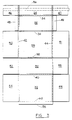
- the embodiment of Figure 1 is made from the blank illustrated in Figure 3.
- the blank incorporates five main panels 24, 26, 28, 30 and 32 which are successively connected to each other along transverse score lines 34, 36, 38, and 40.
- the five main panels, from top to bottom, include a tear strip panel 24, a top panel 26, a back panel 28, a bottom panel 30 and a front panel 32.
- the transverse score lines 34, 36, 38 and 40 define the boundaries of each of these panels 24, 26, 28, 30, and 32 and also serve to connect each panel with the adjacent panels.
- the boundaries of each of these panels 24, 26, 28, 30 and 32 are further defined by axial score lines 42 and 44.
- the axial score lines 42 and 44 also serve to connect each panel 24, 26, 28, 30 and 32 to an end flap 46 through 55 at each transverse edge.
- the end flaps associated with the front panel 32 and the back panel 28 are the major flaps 50, 51, 54 and 55.
- the major flaps 50, 51, 54 and 55 preferably have substantially the same transverse dimension as the axial dimension of the top panel 26; and even more preferably, have substantially the same overall dimensions as the resulting end wall of the container 20.
- the end flaps associated with the bottom panel 30 are the minor flaps 52 and 53.
- the minor flaps 52 and 53 are somewhat smaller in transverse dimension than the major flaps 50, 51, 54 and 55.
- the end flaps associated with the top panel 26 will hereinafter be referred to as ears 48 and 49.
- the transverse dimension of the ears 48 and 49 is substantially smaller than the transverse dimension of the major flaps 50, 51, 54 and 55.
- extension panels 46 and 47 The end flaps associated with the tear strip panel 24 will hereinafter be referred to as extension panels 46 and 47.
- these extension panels 46 and 47 have substantially the same transverse dimension as the major flaps 50, 51, 54 and 55.
- the tear strip panel 24 and its associated extension panels 46 and 47 have a transverse tear strip 56 located therein.
- This tear strip 56 is preferably two transverse parallel lines 50% cut into the outer side of the tear strip panel 24 and extension panels 46 and 47.
- a 50% cut is a continuous cut which extends from the surface of the material down to a depth which is half of the thickness of the material. The 50% cut assures a clean tear at the surface which leaves a relatively pleasing appearance; particularly when the container 20 is printed.
- this tear strip 56 Attached to the inner side of this tear strip 56 is a polypropylene reinforcing tape. This tape helps prevent the tear strip 56 from breaking into two pieces as it is being removed from the container 20. One end of the tear strip 56 extends beyond the axial edge of the extension panel 47. This extension provides a tab which facilitates grasping of the tear strip 56.
- a glue flap 58 is attached to one transverse edge of the front panel 32 via a perforated cut line 60.
- the perforated cut line 60 preferably has cuts which are small enough to prevent substantially all of the granular material from flowing therethrough during shipment as will be discussed hereinafter.
- the blank of Figure 3 is first folded and glued to form the sleeve shown in Figure 5.
- glue is placed in the glue areas 62 and 64 indicated in Figure 4 and the blank is folded 180° about the transverse score line 36 which separates the top panel 26 from the back panel 28.
- the blank is then folded 180° about the transverse score line 40 which separates the front panel 32 from the bottom panel 30.
- the glue flap 58 is adhered to the inner side of the top panel 26 and the tear strip panel 24 and extension panels 46 and 47 are adhered below the tear strip 56 to the front panel 32 and the major flaps 54 and 55 associated therewith.
- This configuration seen in Figure 5, is referred to as a sleeve.
- the sleeve is an economical and efficient form commonly used to ship in containers to the product packager.
- the sleeve is set up, one end is folded and sealed, the container 20 is filled, and then the other end is folded and sealed.
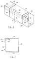
- the sleeve is squared so that each of the five main panels 24, 26, 28, 30 and 32 are at substantially right angles to their adjacent panels.
- the minor flap 52 associated with the bottom panel 30 is first folded 90° about the axial score line 44 to a position perpendicular to the bottom panel 30.
- the major flap 50 associated with the back panel 28 is folded 90° about the axial score line 42 and preferably adhered to the bottom panel 30 end flap 52.
- the major flap 54 associated with the front panel 32 and the tear strip 46 extension panel adhered thereto are then folded 90° about the axial score line 42 and adhered to the exterior side of the major flap 50 of the back panel 28.
- the ear 48 associated with the top wall 26 is folded 90° and adhered to the exterior of the tear strip 24 extension panel 46.
- the top wall 26 ear 48 is folded over and attached such that the top wall 26 is pulled down against the top edge 66 of the major flaps 50 and 54 creating a barrier to granular movement.
- the container 20 is oriented on its side and filled through the remaining open end with a granular material and the other end is folded and sealed.
- the folding and sealing operation of this end is identical to the folding and sealing operation described above. At this point the container 20 is filled, sealed and ready for shipment.
- the container 20 is an enclosure formed by the various panels and flaps. These panels and flaps are the corresponding walls of the container 20.
- the top 26, bottom 30, and back 28 panels are the top 26, bottom 30, and back 28 walls, respectively.
- the front wall 68 is made up of the front panel 32 and the tear strip panel 24.
- the end walls 70 are made from the remaining flaps, panels and ears.
- the top wall 26 opposes the bottom wall 30, the front wall 32 opposes the back wall 28 and the end walls 70 oppose each other.
- each end wall 70 includes a total of five layers.
- the innermost layer is the minor flap 52 associated with the bottom wall 30.
- the second layer is the major flap 50 associated with the back wall 28.
- the middle and fourth layers are the major flap 54 associated with the front wall 32 and the extension panel 46 of the tear strip panel 24, respectively.
- the outermost layer is the ear 48 associated with the top wall 26.
- the top wall 26 is pulled tightly against the top edge 66 of the major flaps 50 and 54. This provides a sift proof barrier which prevents granules from migrating during shipment to the space between the major flap 54 associated with the front wall 32 and the tear strip panel 24 extension panel 46.
- the major end flaps 50 and 54 being coextensive, i.e., having substantially the same dimensions as the end wall 70, provide added strength to the container 20.
- the front wall 68 is formed of two layers.
- the layers of the front wall 68 are formed from the front panel 32 and the tear strip panel 24. These layers are attached to each other below the tear strip 56.
- the top wall 26 has the glue flap 58 attached thereto.
- the glue flap 58 is also attached to the front panel 32 via the perforated cut line 60.
- the perforated cut line 60 substantially prevents the migration of granules in the area between the front panel 32 and the tear strip panel 24. It has been found that virtually any perforation will accomplish this task. Therefore, it is preferred that the perforated cut line 60 barely hold the glue flap 58 to the front panel 32 which makes opening the container 20 easier.
- the perforated cut line 60 of this embodiment is a repeating pattern of a 3/8" cut followed by a 1/16" land.
- the user grasps the tab of the tear strip 56 and pulls the tear strip 56 away from the container 20.
- the top is a three sided lid which is now free to rotate. As the top lid is rotated about the transverse score line 36 which joins the top wall 26 to the back wall 28.
- the glue flap 58 is separated from the front panel 32. Rotating the top lid along this score line 36 to an open position allows access the the contents of the container 20. After dispensing the desired amount of granular products, the container 20 may be closed by rotating the top back to the closed position.
- FIG. 9 A second preferred embodiment can be seen in Figure 9.
- This second embodiment is made from the blank of Figure 10.
- the blank of Figure 10 is virtually identical to the blank of Figure 3. The only difference is that the ears 148 and 149 extend from the tear strip panel 124 extension panels 146 and 147 along transverse score line 134 rather than from the top panel 126.
- the top panel 126 has no end flaps attached to its axial edges. As seen in Figure 9, this blank results in a container 120 having the ears 148 and 149 attached to the top wall 126.
- This blank is folded and glued into the sleeve configuration for shipment to the product packager as with the previous embodiment.
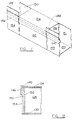
- the container 120 Upon receipt by the packager the container 120 is squared as seen in Figure 11. Folding and sealing the ends requires a slightly different operation, however, than the previous embodiment.
- the bottom panel 130 minor flap 152, the back panel 128 major flap 150, and then the front panel 132 major flap 154 and the tear strip panel 124 extension panel 146 are sequentially folded 90° and glued to the adjacent flaps.
- the ear 148 which is connected to the tear strip panel 124 extension panel 146, is folded about the score line 134 and glued to the top wall 126. This last step is done such that the top panel 126 is pressed tightly against the top edge 166 of the major flaps 150 and 154 creating a sift proof barrier.
- the same operation is followed to seal the other end of the container 120.
- each end wall consists of four layers.
- the innermost layer is the bottom panel 130 minor flap 152.
- the next layers are the back wall 128 major flap 150 followed by the front wall 132 major flap 154.
- the outer most layer is the tear strip 124 extension panel 146.
- the top wall 26 has the ear 148 attached thereto. The ear 148 is connected along the score line 134 to the tear strip extension panel 146.
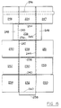
- a third preferred embodiment of the container 220, seen in Figures 13 and 14, is made from the blank of Figure 15.
- This embodiment has a generally cube shape.
- the modifications of this embodiment could, however, be incorporated into the embodiments of Figures 1 and 9.
- One main difference between the blank of Figure 15 and the blank of Figure 3 is the size of the tear strip panel 224 and the extension panels 246 and 247 associated therewith.
- the tear strip panel 24 of Figure 3 has an axial dimension which is substantially less than the axial dimension of the front panel 32.
- the tear strip panel 224 of Figure 15, however, has an axial dimension substantially equivalent to the axial dimension of the front panel 232.
- the tear strip panel 224 extension panels 246 and 247 are substantially identical in overall dimension to the major flaps 250, 251, 254 and 255.
- each layer of the front wall 268 is coextensive.
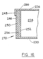
- the embodiment of Figure 13 is seen in cross section in Figure 16.
- the end wall 270 includes 5 layers. These are the same five layers as with the embodiment of Figure 1. The only difference being that the tear strip panel 224 extension panels 246 and 247 are full sized, i.e., they have substantially the same overall dimensions as the end wall 270.
Landscapes
- Engineering & Computer Science (AREA)
- Mechanical Engineering (AREA)
- Cartons (AREA)
- Jellies, Jams, And Syrups (AREA)
- General Preparation And Processing Of Foods (AREA)
- Fertilizers (AREA)
- Formation And Processing Of Food Products (AREA)
- Manufacturing Of Micro-Capsules (AREA)
- Preparation Of Clay, And Manufacture Of Mixtures Containing Clay Or Cement (AREA)
- Packages (AREA)
Abstract
Description
- The present invention relates to cartonboard containers as defined in the preamble of claim 1, and more particularly, to such containers which are suitable for housing granular materials as well as to a blank for forming such a container.
- Cartonboard containers have been available for many years. The ability to readily fill, open and dispense from these containers have long been important goals of those skilled in the art. One way to accomplish these goals is to use a side fill container which can be opened by the removal of a tear strip. These containers are commonly used for housing products such as ice cream. Examples of these containers are found in various United States Patents, one of which is US-3 131 852. This patent discloses a side fill, tear strip opening container for the automatic packaging of such products as ice cream according to the preambles of claim 1 and claim 9.
- One patent of particular interest is United States Patent 3,239,129 which issued to Schilling et al. on March 8, 1966. This Patent discloses a side fill, tear strip opening container. The front wall of the container is made with an inner and an outer layer; the tear strip is in the outer layer. The end walls of the container include five total layers; only one of which has the same overall dimensions as the end wall.
- Existing containers of this type, however, suffer from at least one major drawback when used with granular materials. They are generally not sift proof and spillage, therefore, often accompanies transporting and opening of the container. During transit the granules migrate into the spaces between layers and through any cracks and crevices. For example, the granules have a way of working themselves between the inner layer which remains stationary and the outer layer which is moved during opening. Thus, when the outer layer is moved as the carton is opened these granules are left unsupported and fall. The resulting mess that is created is unsatisfactory to consumers.
- Accordingly, it is an object of the present invention to provide a container for housing granular materials which is easy to fill, open and dispense therefrom;
- It is also an object of the present invention to provide such a container which substantially eliminates the problem of granular contents spilling upon opening;
- It is additionally an object of the present invention to provide such a container which is filled from the side;
- It is further an object of the present invention to provide such a container which is opened by the removal of a tear strip, forming a reclosing lid;
- It is lastly an object of the present invention to provide a container which accomplishes the aforementioned objectives at minimal costs. The primary objects of the present invention are solved by the characterising features of claims 1 and 9 respectively.
- In accordance with one aspect of the present invention a side fill container is provided for housing granular material. The container is a six sided enclosure including a top wall and a bottom wall opposing each other, a front wall and a back wall opposing each other and two side walls opposing each other. Each of the end walls has two main layers attached to each other in face to face relation. The main layers have a top edge. Said main layers have a transverse dimension substantially equivalent to the axial dimension of the top wall. A third layer is attached to the main layers. A fourth layer which has a horizontal tear strip therein is attached to the outside of the main layers below the tear strip. The front wall has an inner layer with a top edge and an outer layer. The outer layer has a horizontal tear strip therein which connects with the tear strips of the end walls to form one continuous tear strip. The inner and outer layers are attached to each other below the tear strip. An ear is attached to each end wall above the tear strip and is also attached to the top wall. The ear holds the top wall against the top edge of the main layers. A glue flap is attached to the top edge of the inner layer of the front wall via a perforated score line. The glue flap is also attached to the top wall.
- In accordance with another aspect of the present invention a blank is provided for forming the above-described container. The blank includes a tear strip panel which has an extension panel attached along axial score lines to each axial edge of the tear strip panel. The tear strip panel and extension panels have a transverse tear strip therein. A top panel is attached along its upper transverse edge to the lower transverse edge of the tear strip panel. A back panel is attached along its upper transverse edge to the lower transverse edge of the top panel. The back panel has a major flap with a transverse dimension substantially equivalent to the axial dimension of the top panel attached along axial score lines to each axial edge of the back panel. A bottom panel is attached along its upper transverse edge to the lower transverse edge of the back panel. The bottom panel has a minor flap attached along axial score lines to each axial edge of the bottom panel. A front panel is attached along its upper transverse edge to the lower transverse edge of the bottom panel. The front panel has a major flap with a transverse dimension substantially equivalent to the axial dimension of the top panel attached along axial score lines to each axial edge of the front panel. An ear is attached along a score line to either each axial edge of the top panel or each lower transverse edge of the tear strip extension panels. A glue flap is attached along its upper transverse edge to the lower transverse edge of the front panel via a transverse perforated cut line.
- While the specification concludes with claims which particularly point out and distinctly claim the invention, it is believed the present invention will be better understood from the following description of preferred embodiments taken in conjunction with the accompanying drawings, in which like reference numerals identify identical elements and wherein;
- Figure 1 is a perspective view of a preferred embodiment of the present invention, seen in the closed orientation;
- Figure 2 is a perspective view of the container of Figure 1, seen in an open orientation;
- Figure 3 is a top plan view of the blank used to make the container of Figure 1;
- Figure 4 is a top plan view of the blank of Figure 3 after initial folding, showing the glue areas;
- Figure 5 is a top plan view of the sleeve made from the blank of Figure 3;
- Figure 6 is a perspective view of the blank of Figure 3 after being squared for transformation into the container of Figure 1;
- Figure 7 is a cross-sectional view taken along line 7-7 of Figure 6 showing the wall construction of the container of Figure 1;
- Figure 8 is a fragmentary cross-sectional view taken along line 8-8 of Figure 1 showing the wall construction of the container of Figure 1;
- Figure 9 is a perspective view of a second preferred embodiment of the present invention, seen in the closed orientation;
- Figure 10 is a top plan view of the blank used to make the container of Figure 9;
- Figure 11 is a perspective view of the blank of Figure 10 after being squared for transformation into the container of Figure 9;
- Figure 12 is a fragmentary cross-sectional view taken along line 12-12 of Figure 9 showing the wall construction of the preferred embodiment;
- Figure 13 is a perspective view of a third preferred embodiment of the present invention, seen in the closed orientation;
- Figure 14 is a perspective view of the container of Figure 13, seen in the open orientation;
- Figure 15 is a top plan view of the blank used to make the preferred embodiment of Figure 13;
- Figure 16 is a fragmentary cross-sectional view taken along line 16-16 of Figure 13 showing the wall construction of that container.
- In a particularly preferred embodiment seen in Figure 1, the present invention provides a side fill carton for housing granular materials, indicated generally as 20. The embodiment of Figure 1 is made from the blank illustrated in Figure 3.
- Referring to Figure 3, the blank incorporates five
main panels transverse score lines tear strip panel 24, atop panel 26, aback panel 28, abottom panel 30 and afront panel 32. Thetransverse score lines panels panels axial score lines axial score lines panel end flap 46 through 55 at each transverse edge. - The end flaps associated with the
front panel 32 and theback panel 28 are themajor flaps major flaps top panel 26; and even more preferably, have substantially the same overall dimensions as the resulting end wall of thecontainer 20. The end flaps associated with thebottom panel 30 are theminor flaps major flaps top panel 26 will hereinafter be referred to asears ears major flaps - The end flaps associated with the
tear strip panel 24 will hereinafter be referred to asextension panels extension panels major flaps tear strip panel 24 and its associatedextension panels transverse tear strip 56 located therein. Thistear strip 56 is preferably two transverseparallel lines 50% cut into the outer side of thetear strip panel 24 andextension panels container 20 is printed. Attached to the inner side of thistear strip 56 is a polypropylene reinforcing tape. This tape helps prevent thetear strip 56 from breaking into two pieces as it is being removed from thecontainer 20. One end of thetear strip 56 extends beyond the axial edge of theextension panel 47. This extension provides a tab which facilitates grasping of thetear strip 56. - A
glue flap 58 is attached to one transverse edge of thefront panel 32 via aperforated cut line 60. Theperforated cut line 60 preferably has cuts which are small enough to prevent substantially all of the granular material from flowing therethrough during shipment as will be discussed hereinafter. - To assemble the
container 20 the blank of Figure 3 is first folded and glued to form the sleeve shown in Figure 5. Initially glue is placed in theglue areas transverse score line 36 which separates thetop panel 26 from theback panel 28. The blank is then folded 180° about thetransverse score line 40 which separates thefront panel 32 from thebottom panel 30. Thus, theglue flap 58 is adhered to the inner side of thetop panel 26 and thetear strip panel 24 andextension panels tear strip 56 to thefront panel 32 and themajor flaps - Once received by the product packager the sleeve is set up, one end is folded and sealed, the
container 20 is filled, and then the other end is folded and sealed. As seen in Figure 6, to set up thecontainer 20 the sleeve is squared so that each of the fivemain panels minor flap 52 associated with thebottom panel 30 is first folded 90° about theaxial score line 44 to a position perpendicular to thebottom panel 30. Themajor flap 50 associated with theback panel 28 is folded 90° about theaxial score line 42 and preferably adhered to thebottom panel 30end flap 52. Themajor flap 54 associated with thefront panel 32 and thetear strip 46 extension panel adhered thereto are then folded 90° about theaxial score line 42 and adhered to the exterior side of themajor flap 50 of theback panel 28. Lastly, theear 48 associated with thetop wall 26 is folded 90° and adhered to the exterior of thetear strip 24extension panel 46. As seen in Figure 8, thetop wall 26ear 48 is folded over and attached such that thetop wall 26 is pulled down against thetop edge 66 of themajor flaps - The
container 20 is oriented on its side and filled through the remaining open end with a granular material and the other end is folded and sealed. The folding and sealing operation of this end is identical to the folding and sealing operation described above. At this point thecontainer 20 is filled, sealed and ready for shipment. - Referring to Figure 1, the
container 20 is an enclosure formed by the various panels and flaps. These panels and flaps are the corresponding walls of thecontainer 20. The top 26, bottom 30, and back 28 panels are the top 26, bottom 30, and back 28 walls, respectively. Thefront wall 68 is made up of thefront panel 32 and thetear strip panel 24. Theend walls 70 are made from the remaining flaps, panels and ears. Thetop wall 26 opposes thebottom wall 30, thefront wall 32 opposes theback wall 28 and theend walls 70 oppose each other. - The walls of the
container 20 as assembled are seen in Figures 7 and 8. Referring to Figure 8, eachend wall 70 includes a total of five layers. The innermost layer is theminor flap 52 associated with thebottom wall 30. The second layer is themajor flap 50 associated with theback wall 28. The middle and fourth layers are themajor flap 54 associated with thefront wall 32 and theextension panel 46 of thetear strip panel 24, respectively. The outermost layer is theear 48 associated with thetop wall 26. As seen in the drawing, thetop wall 26 is pulled tightly against thetop edge 66 of themajor flaps major flap 54 associated with thefront wall 32 and thetear strip panel 24extension panel 46. If granules migrate to this area spillage will result upon opening of thecontainer 20. In addition to providing a sift proof barrier, the major end flaps 50 and 54, being coextensive, i.e., having substantially the same dimensions as theend wall 70, provide added strength to thecontainer 20. - Referring to Figure 7, the
front wall 68 is formed of two layers. The layers of thefront wall 68 are formed from thefront panel 32 and thetear strip panel 24. These layers are attached to each other below thetear strip 56. Thetop wall 26 has theglue flap 58 attached thereto. Theglue flap 58 is also attached to thefront panel 32 via theperforated cut line 60. Theperforated cut line 60 substantially prevents the migration of granules in the area between thefront panel 32 and thetear strip panel 24. It has been found that virtually any perforation will accomplish this task. Therefore, it is preferred that theperforated cut line 60 barely hold theglue flap 58 to thefront panel 32 which makes opening thecontainer 20 easier. Theperforated cut line 60 of this embodiment is a repeating pattern of a 3/8" cut followed by a 1/16" land. - To open the
container 20 the user grasps the tab of thetear strip 56 and pulls thetear strip 56 away from thecontainer 20. This separates the top, which includes thetear strip panel 24 and associatedpanel extensions tear strip 56, thetop wall 68 and theears container 20. The top is a three sided lid which is now free to rotate. As the top lid is rotated about thetransverse score line 36 which joins thetop wall 26 to theback wall 28. Theglue flap 58 is separated from thefront panel 32. Rotating the top lid along thisscore line 36 to an open position allows access the the contents of thecontainer 20. After dispensing the desired amount of granular products, thecontainer 20 may be closed by rotating the top back to the closed position. - A second preferred embodiment can be seen in Figure 9. This second embodiment is made from the blank of Figure 10. The blank of Figure 10 is virtually identical to the blank of Figure 3. The only difference is that the
ears tear strip panel 124extension panels transverse score line 134 rather than from thetop panel 126. Thetop panel 126 has no end flaps attached to its axial edges. As seen in Figure 9, this blank results in acontainer 120 having theears top wall 126. - This blank is folded and glued into the sleeve configuration for shipment to the product packager as with the previous embodiment. Upon receipt by the packager the
container 120 is squared as seen in Figure 11. Folding and sealing the ends requires a slightly different operation, however, than the previous embodiment. As described before thebottom panel 130minor flap 152, theback panel 128major flap 150, and then thefront panel 132major flap 154 and thetear strip panel 124extension panel 146 are sequentially folded 90° and glued to the adjacent flaps. Then theear 148 which is connected to thetear strip panel 124extension panel 146, is folded about thescore line 134 and glued to thetop wall 126. This last step is done such that thetop panel 126 is pressed tightly against the top edge 166 of themajor flaps container 120. - Referring to Figure 12, the
container 120 of Figure 9 is shown in cross section. Each end wall consists of four layers. The innermost layer is thebottom panel 130minor flap 152. The next layers are theback wall 128major flap 150 followed by thefront wall 132major flap 154. The outer most layer is thetear strip 124extension panel 146. Thetop wall 26 has theear 148 attached thereto. Theear 148 is connected along thescore line 134 to the tearstrip extension panel 146. - A third preferred embodiment of the
container 220, seen in Figures 13 and 14, is made from the blank of Figure 15. This embodiment has a generally cube shape. The modifications of this embodiment could, however, be incorporated into the embodiments of Figures 1 and 9. One main difference between the blank of Figure 15 and the blank of Figure 3 is the size of thetear strip panel 224 and theextension panels tear strip panel 24 of Figure 3 has an axial dimension which is substantially less than the axial dimension of thefront panel 32. Thetear strip panel 224 of Figure 15, however, has an axial dimension substantially equivalent to the axial dimension of thefront panel 232. Additionally, thetear strip panel 224extension panels major flaps - Another main difference between the blanks of Figures 3 and 15 is that the
minor flaps bottom wall 230 are substantially equivalent in axial dimension and only slightly shorter in transverse dimension than themajor flaps axial score lines ears top wall 226 are slightly further apart than theaxial score lines perforated cut line 260. Theperforated cut line 260 of this embodiment is a repeating pattern of a 3/16" cut followed by a 1/32" land. - The blank is folded and glued like the other embodiments into the sleeve configuration. The sleeve is squared and folded and sealed using the identical procedure discussed with reference to the embodiment of Figure 1. In this embodiment, each layer of the front wall 268 is coextensive.
- The embodiment of Figure 13 is seen in cross section in Figure 16. Referring to Figure 16, the
end wall 270 includes 5 layers. These are the same five layers as with the embodiment of Figure 1. The only difference being that thetear strip panel 224extension panels end wall 270. - Although particular embodiments of the present invention have been shown and described, modification may be made to the package without departing from the teachings of the present invention. Accordingly, the present invention comprises all embodiments within the scope of the appended claims.
Claims (10)
- A side fill container (20) for housing granular materials, the container has an enclosure including a top wall (26) and a bottom wall (30) opposing each other, a front wall (68) and a back wall (28) opposing each other, and two end walls (70) opposing each other, whereby :(a) each of the end walls (70) comprises two main layers (50, 54; 51, 55) associated with said back (28) and front (68) walls attached to each other in face to face relation and having a top edge (66), a third layer (52, 53) associated with said bottom wall (30) attached in face to face relation to the main layers, and a fourth layer (46, 47) having a horizontal tear strip (56) therein, the fourth layer is attached to the main layers below the tear strip;(b) the front wall (68) comprises an inner layer (32) having a top edge and an outer layer (24), the outer layer having a horizontal tear strip (56) therein which connects with the tear strips of the end walls (70) forming one continuous tear strip, the inner and outer layers being attached to each other below the tear strip;(c) an ear (48, 49) is attached to each of the end walls (70) above the tear strip (56) and to the top wall (26), the ear holding the top wall against the top edge (66) of the main layers (50, 54; 51, 55), a glue flap (58) is attached to the top edge of the inner layer (32) of the front wall (68),characterized in that the fourth layer (46, 47) is attached to the main layers (50, 54; 51, 55) below the tear strip (56), the glue flap (58) is attached to the top edge of the inner layer (32) of the front wall (68) via a perforated score line (60), the glue flap also being attached to the top wall (26), and said two main layers (50, 54; 51, 55) have substantially the same transverse dimension as the axial dimension of said top wall.
- A side fill container according to claim 1, wherein the main layers (50, 54; 51, 55), are coextensive with each other.
- A side fill container according to claim 1 or claim 2, wherein each ear (48, 49) is attached to the top wall (26) along a score line (42, 44).
- A side fill container according to any one of the preceding claims, wherein each ear (48, 49) is attached to a layer of the end wall (70) along a score line (42, 44).
- A side fill container according to any one of the preceding claims wherein the tear strip panel (24) is coextensive with the front panel (32).
- A side fill container according to any one of the preceding claims wherein the two main layers are the main flaps (50, 51, 54, 55) extending from the front (68) and back walls (28) respectively and attached thereto along score lines (42, 44).
- A side fill container according to any one of the preceding claims wherein the third layer is the minor flap (52, 53) extending from the bottom panel (30) and attached thereto along a score line (42, 44).
- A side fill container according to any one of the preceding claims wherein the fourth layer is the extension panel (46, 47) of the tear strip panel (24).
- A blank for forming a side fill container (20) according to claim 1, said blank comprising top (26), bottom (30), front (32) and back (28) wall panels, and a tear strip panel (24), whereby :(a) the tear strip panel (24) has an extension panel (46, 47) attached along axial score lines (42, 44) to each axial edge of the tear strip panel, the tear strip panel and extension panels having a transverse tear strip (56) therein;b) the top panel (26) is attached along its upper transverse edge (34) to the lower transverse edge (34) of the tear strip panel (24);(c) the back panel (28) is attached along its upper transverse edge (36) to the lower transverse edge (36) of the top panel (26), the back panel having a major flap (50, 51) having a transverse dimension substantially equivalent to the axial dimension of the top panel attached along axial score lines (42, 44) to the each axial edge the back panel;(d) the bottom panel (30) is attached along its upper transverse edge (38) to the lower transverse edge (38) of the back panel (28), the bottom panel having a minor flap (52, 53) attached along axial score lines (42, 44) to each axial edge of the bottom panel;(e) the front panel (32) being attached along its upper transverse edge (40) to the lower transverse edge (40) of the bottom panel (30), the front panel having a major flap (54,55) having a transverse dimension substantially equivalent to the axial dimension of the top panel (26) attached along axial score lines (42, 44) to each axial edge of the front panel;(f) an ear (48, 49; 148, 149) being attached along a score line (42, 44) to either each axial edge of the top panel (26) or each lower transverse edge (134) of the tear strip extension panels (146, 147), a glue flap (58) is attached along its upper transverse edge to the lower transverse edge of the front panel (32) via a transverse perforated cut line (60);characterized in that the back panel (28) has a major flap (50, 51) having a transverse dimension substantially equivalent to the axial dimension of the top panel (26) attached along axial score lines (42,44) to each axial edge of the back panel, and a glue flap (58) which is attached along its upper transverse edge to the lower transverse edge of the front panel (32) via a transverse perforated cut line (60).
- A blank according to claim 9, wherein the major (50, 51, 54, 55) and minor (52, 53) flaps have substantially the same transverse dimensions.
Applications Claiming Priority (3)
| Application Number | Priority Date | Filing Date | Title |
|---|---|---|---|
| US07/495,258 US5007541A (en) | 1990-03-16 | 1990-03-16 | Carton for granular materials |
| PCT/US1991/001389 WO1991013808A1 (en) | 1990-03-16 | 1991-03-01 | Carton for granular materials |
| US495258 | 2000-01-31 |
Publications (3)
| Publication Number | Publication Date |
|---|---|
| EP0588789A4 EP0588789A4 (en) | 1993-06-14 |
| EP0588789A1 EP0588789A1 (en) | 1994-03-30 |
| EP0588789B1 true EP0588789B1 (en) | 1996-05-08 |
Family
ID=23967929
Family Applications (1)
| Application Number | Title | Priority Date | Filing Date |
|---|---|---|---|
| EP91906332A Expired - Lifetime EP0588789B1 (en) | 1990-03-16 | 1991-03-01 | Carton for granular materials |
Country Status (14)
| Country | Link |
|---|---|
| US (1) | US5007541A (en) |
| EP (1) | EP0588789B1 (en) |
| JP (1) | JP3048633B2 (en) |
| AT (1) | ATE137714T1 (en) |
| CA (1) | CA2076968C (en) |
| DE (1) | DE69119437T2 (en) |
| DK (1) | DK0588789T3 (en) |
| ES (1) | ES2087290T3 (en) |
| GR (1) | GR3019867T3 (en) |
| IE (1) | IE77636B1 (en) |
| MX (1) | MX173839B (en) |
| SA (1) | SA91110389B1 (en) |
| TR (1) | TR25446A (en) |
| WO (1) | WO1991013808A1 (en) |
Cited By (1)
| Publication number | Priority date | Publication date | Assignee | Title |
|---|---|---|---|---|
| WO1999002411A1 (en) | 1997-07-10 | 1999-01-21 | The Procter & Gamble Company | Carton for granular materials, die cut and process for forming such a carton |
Families Citing this family (16)
| Publication number | Priority date | Publication date | Assignee | Title |
|---|---|---|---|---|
| FI90519C (en) * | 1990-10-15 | 1994-02-25 | Ahlstroem Eurapak Oy | Packaging |
| US5161734A (en) * | 1991-05-10 | 1992-11-10 | Procter & Gamble | Reclosable carton for granular materials |
| US5297727A (en) * | 1992-05-29 | 1994-03-29 | Brioux Murray J | Carton |
| US5287969A (en) * | 1992-10-30 | 1994-02-22 | Any Side Up, Inc. | Orientation-insensitive shipping carton |
| US5505374A (en) * | 1995-07-13 | 1996-04-09 | Packaging Corporation Of America | Flip-top reclosable carton and method of making the same |
| US5757220A (en) * | 1996-12-23 | 1998-05-26 | Analog Devices, Inc. | Digitally controlled programmable attenuator |
| EP0928744B1 (en) | 1998-01-08 | 2002-11-13 | The Procter & Gamble Company | Carton for granular materials with extra cover |
| EP0941935A1 (en) | 1998-03-13 | 1999-09-15 | The Procter & Gamble Company | Two-compartment carton for granular materials |
| WO2002011516A1 (en) | 1999-05-12 | 2002-02-14 | The Procter & Gamble Company | Carton with an object fitted to the lid |
| US6860301B2 (en) | 2001-07-11 | 2005-03-01 | Degussa Ag | Apparatus and process for filling large containers of different sizes and shapes |
| CA2452775C (en) * | 2001-07-11 | 2007-09-25 | Evonik Operations Gmbh | Filling containers with granular or pulverulent material |
| CA2674473C (en) * | 2007-01-05 | 2012-08-28 | Graphic Packaging International, Inc. | Cooler box with handle round |
| US8136717B2 (en) * | 2008-05-08 | 2012-03-20 | Graphic Packaging International, Inc. | Cooler carton with zipper opening feature |
| DE202009009934U1 (en) * | 2009-07-20 | 2009-11-26 | A & R Carton Bremen Gmbh | Folding box for frozen food and apparatus for producing the folding box |
| US10377525B2 (en) | 2017-12-08 | 2019-08-13 | Saba Saba | Package with auxiliary container lid |
| GB2589333B (en) * | 2019-11-26 | 2022-03-09 | Ready Case Ltd | Packing case with tear strip |
Family Cites Families (26)
| Publication number | Priority date | Publication date | Assignee | Title |
|---|---|---|---|---|
| CA814827A (en) * | 1969-06-10 | M. Tolaas William | Easy opening cartons | |
| US1793025A (en) * | 1929-03-20 | 1931-02-17 | Louis J Spitzenberger | Collapsible box |
| US2122885A (en) * | 1936-08-21 | 1938-07-05 | Container Corp | Container |
| US2919060A (en) * | 1954-04-21 | 1959-12-29 | Green Bay Box Company | Carton |
| US3111255A (en) * | 1961-02-16 | 1963-11-19 | American Can Co | Carton |
| US3131851A (en) * | 1962-05-22 | 1964-05-05 | St Regis Paper Co | Paperboard carton |
| US3197114A (en) * | 1962-09-27 | 1965-07-27 | Riegel Paper Corp | Top opening ice cream carton |
| US3131852A (en) * | 1963-05-29 | 1964-05-05 | West Virginia Pulp & Paper Co | Reinforced carton |
| US3219257A (en) * | 1963-08-16 | 1965-11-23 | Ralph F Anderson | Carton construction |
| US3168975A (en) * | 1963-09-11 | 1965-02-09 | Kvp Sutherland Paper Co | Carton having tear strip in cover flaps |
| US3197115A (en) * | 1964-03-23 | 1965-07-27 | West Virginia Pulp & Paper Co | Ice cream carton |
| US3206103A (en) * | 1964-07-17 | 1965-09-14 | Diamond Int Corp | Reclosable tamper-proof carton |
| US3239129A (en) * | 1964-10-16 | 1966-03-08 | American Can Co | Carton |
| US3283991A (en) * | 1964-11-09 | 1966-11-08 | Waldorf Paper Prod Co | Reclosable cartons |
| US3252651A (en) * | 1964-11-12 | 1966-05-24 | Riegel Paper Corp | Sealed end ice cream carton |
| US3338505A (en) * | 1965-12-13 | 1967-08-29 | Hoerner Waldorf Corp | Reclosable cartons |
| US3409205A (en) * | 1966-09-21 | 1968-11-05 | American Can Co | Carton with attached cover |
| US3434849A (en) * | 1966-11-04 | 1969-03-25 | Dow Chemical Co | Insulated frozen dessert packages |
| US3441193A (en) * | 1967-11-16 | 1969-04-29 | James W Castle | Side loading egg case |
| GB1248131A (en) * | 1968-02-08 | 1971-09-29 | Waddington Ltd J | Improvements in cartons |
| US3593911A (en) * | 1969-05-14 | 1971-07-20 | Fibreboard Corp | Removable tape for recloseable carton |
| US4289239A (en) * | 1978-03-07 | 1981-09-15 | American Can Company | Carton having novel end panel construction |
| US4289240A (en) * | 1979-10-01 | 1981-09-15 | American Can Company | Flip-lock reclosable carton |
| DE3602974A1 (en) * | 1986-01-31 | 1987-08-06 | Unilever Nv | Packaging for ice cream |
| US4679694A (en) * | 1986-04-15 | 1987-07-14 | Rendoll Paper Company | Carton and blank for packaging ice cream or the like |
| US4712730A (en) * | 1986-05-23 | 1987-12-15 | Froom Thomas W | Ice-cream carton, carton blank, and method of erecting same |
-
1990
- 1990-03-16 US US07/495,258 patent/US5007541A/en not_active Expired - Lifetime
-
1991
- 1991-03-01 CA CA002076968A patent/CA2076968C/en not_active Expired - Fee Related
- 1991-03-01 DK DK91906332.1T patent/DK0588789T3/en active
- 1991-03-01 EP EP91906332A patent/EP0588789B1/en not_active Expired - Lifetime
- 1991-03-01 ES ES91906332T patent/ES2087290T3/en not_active Expired - Lifetime
- 1991-03-01 WO PCT/US1991/001389 patent/WO1991013808A1/en not_active Ceased
- 1991-03-01 DE DE69119437T patent/DE69119437T2/en not_active Expired - Fee Related
- 1991-03-01 JP JP3506106A patent/JP3048633B2/en not_active Expired - Fee Related
- 1991-03-01 AT AT91906332T patent/ATE137714T1/en not_active IP Right Cessation
- 1991-03-12 TR TR91/0252A patent/TR25446A/en unknown
- 1991-03-15 IE IE88791A patent/IE77636B1/en not_active IP Right Cessation
- 1991-03-15 MX MX024942A patent/MX173839B/en unknown
- 1991-06-08 SA SA91110389A patent/SA91110389B1/en unknown
-
1996
- 1996-05-09 GR GR960401076T patent/GR3019867T3/en unknown
Cited By (1)
| Publication number | Priority date | Publication date | Assignee | Title |
|---|---|---|---|---|
| WO1999002411A1 (en) | 1997-07-10 | 1999-01-21 | The Procter & Gamble Company | Carton for granular materials, die cut and process for forming such a carton |
Also Published As
| Publication number | Publication date |
|---|---|
| GR3019867T3 (en) | 1996-08-31 |
| JP3048633B2 (en) | 2000-06-05 |
| US5007541A (en) | 1991-04-16 |
| MX173839B (en) | 1994-03-30 |
| IE910887A1 (en) | 1991-10-09 |
| JPH05505784A (en) | 1993-08-26 |
| EP0588789A1 (en) | 1994-03-30 |
| SA91110389B1 (en) | 2002-10-30 |
| DE69119437D1 (en) | 1996-06-13 |
| WO1991013808A1 (en) | 1991-09-19 |
| ES2087290T3 (en) | 1996-07-16 |
| CA2076968A1 (en) | 1991-09-17 |
| TR25446A (en) | 1993-05-01 |
| DK0588789T3 (en) | 1996-05-28 |
| CA2076968C (en) | 1996-05-07 |
| EP0588789A4 (en) | 1993-06-14 |
| IE77636B1 (en) | 1997-12-31 |
| ATE137714T1 (en) | 1996-05-15 |
| DE69119437T2 (en) | 1996-10-24 |
Similar Documents
| Publication | Publication Date | Title |
|---|---|---|
| EP0583380B1 (en) | Reclosable carton for granular materials | |
| US5007541A (en) | Carton for granular materials | |
| US5458272A (en) | Paperboard dispenser having separately formed drawer | |
| US3263899A (en) | Carton tear strip arrangement with reclosure feature | |
| US4752029A (en) | Carton with integral display bin | |
| US6932265B2 (en) | Box convertible to a display container and method of making same | |
| US3426955A (en) | Combination bag and box | |
| US5860526A (en) | Apparatus and method for retaining a cylindrical shaped product or container within a shadow carton so that the front label on the product or container does not rotate out of view | |
| US5330099A (en) | Container for foodstuffs | |
| CA2477338C (en) | Recloseable carton | |
| US3353740A (en) | Reclosable carton | |
| US3163351A (en) | Package | |
| US4361266A (en) | Coated paperboard food package | |
| CA1314272C (en) | Opening arrangement for gable top container | |
| US5325989A (en) | Box and blank for packaging powdered soap or the like | |
| CA1095857A (en) | Sift-proof, shiping and dispensing container | |
| US4228898A (en) | Reclosable carton and blank therefor | |
| EP0070886A1 (en) | EASY TO OPEN BOX. | |
| US4982846A (en) | Sift-proof carton and blank therefor | |
| WO2025080920A1 (en) | Container with liner | |
| US3567102A (en) | Dispensing carton | |
| US3469767A (en) | Box and box blank | |
| GB2264287A (en) | A container | |
| US3269642A (en) | Container construction | |
| US2701091A (en) | Container |
Legal Events
| Date | Code | Title | Description |
|---|---|---|---|
| PUAI | Public reference made under article 153(3) epc to a published international application that has entered the european phase |
Free format text: ORIGINAL CODE: 0009012 |
|
| 17P | Request for examination filed |
Effective date: 19930210 |
|
| AK | Designated contracting states |
Kind code of ref document: A1 Designated state(s): AT BE CH DE DK ES FR GB GR IT LI LU NL SE |
|
| 17Q | First examination report despatched |
Effective date: 19950109 |
|
| GRAH | Despatch of communication of intention to grant a patent |
Free format text: ORIGINAL CODE: EPIDOS IGRA |
|
| GRAA | (expected) grant |
Free format text: ORIGINAL CODE: 0009210 |
|
| AK | Designated contracting states |
Kind code of ref document: B1 Designated state(s): AT BE CH DE DK ES FR GB GR IT LI LU NL SE |
|
| REF | Corresponds to: |
Ref document number: 137714 Country of ref document: AT Date of ref document: 19960515 Kind code of ref document: T |
|
| REG | Reference to a national code |
Ref country code: CH Ref legal event code: NV Representative=s name: RITSCHER & SEIFERT PATENTANWAELTE VSP |
|
| REG | Reference to a national code |
Ref country code: DK Ref legal event code: T3 |
|
| REG | Reference to a national code |
Ref country code: ES Ref legal event code: BA2A Ref document number: 2087290 Country of ref document: ES Kind code of ref document: T3 |
|
| REF | Corresponds to: |
Ref document number: 69119437 Country of ref document: DE Date of ref document: 19960613 |
|
| ET | Fr: translation filed | ||
| REG | Reference to a national code |
Ref country code: ES Ref legal event code: FG2A Ref document number: 2087290 Country of ref document: ES Kind code of ref document: T3 |
|
| ITF | It: translation for a ep patent filed | ||
| REG | Reference to a national code |
Ref country code: GR Ref legal event code: FG4A Free format text: 3019867 |
|
| PLBI | Opposition filed |
Free format text: ORIGINAL CODE: 0009260 |
|
| PLBF | Reply of patent proprietor to notice(s) of opposition |
Free format text: ORIGINAL CODE: EPIDOS OBSO |
|
| 26 | Opposition filed |
Opponent name: HENKEL KGAA PATENTE (TTP) Effective date: 19970203 |
|
| NLR1 | Nl: opposition has been filed with the epo |
Opponent name: HENKEL KGAA PATENTE (TTP) |
|
| PLBF | Reply of patent proprietor to notice(s) of opposition |
Free format text: ORIGINAL CODE: EPIDOS OBSO |
|
| PLBF | Reply of patent proprietor to notice(s) of opposition |
Free format text: ORIGINAL CODE: EPIDOS OBSO |
|
| PLBO | Opposition rejected |
Free format text: ORIGINAL CODE: EPIDOS REJO |
|
| APAC | Appeal dossier modified |
Free format text: ORIGINAL CODE: EPIDOS NOAPO |
|
| APAE | Appeal reference modified |
Free format text: ORIGINAL CODE: EPIDOS REFNO |
|
| APAC | Appeal dossier modified |
Free format text: ORIGINAL CODE: EPIDOS NOAPO |
|
| APAC | Appeal dossier modified |
Free format text: ORIGINAL CODE: EPIDOS NOAPO |
|
| REG | Reference to a national code |
Ref country code: GB Ref legal event code: IF02 |
|
| PLBN | Opposition rejected |
Free format text: ORIGINAL CODE: 0009273 |
|
| STAA | Information on the status of an ep patent application or granted ep patent |
Free format text: STATUS: OPPOSITION REJECTED |
|
| 27O | Opposition rejected |
Effective date: 20011113 |
|
| NLR2 | Nl: decision of opposition | ||
| PGFP | Annual fee paid to national office [announced via postgrant information from national office to epo] |
Ref country code: GR Payment date: 20040116 Year of fee payment: 14 |
|
| PGFP | Annual fee paid to national office [announced via postgrant information from national office to epo] |
Ref country code: LU Payment date: 20040121 Year of fee payment: 14 |
|
| PGFP | Annual fee paid to national office [announced via postgrant information from national office to epo] |
Ref country code: DK Payment date: 20040123 Year of fee payment: 14 |
|
| PGFP | Annual fee paid to national office [announced via postgrant information from national office to epo] |
Ref country code: GB Payment date: 20040205 Year of fee payment: 14 Ref country code: AT Payment date: 20040205 Year of fee payment: 14 |
|
| PGFP | Annual fee paid to national office [announced via postgrant information from national office to epo] |
Ref country code: NL Payment date: 20040209 Year of fee payment: 14 |
|
| PGFP | Annual fee paid to national office [announced via postgrant information from national office to epo] |
Ref country code: FR Payment date: 20040302 Year of fee payment: 14 |
|
| PGFP | Annual fee paid to national office [announced via postgrant information from national office to epo] |
Ref country code: SE Payment date: 20040303 Year of fee payment: 14 |
|
| PGFP | Annual fee paid to national office [announced via postgrant information from national office to epo] |
Ref country code: ES Payment date: 20040317 Year of fee payment: 14 |
|
| PGFP | Annual fee paid to national office [announced via postgrant information from national office to epo] |
Ref country code: CH Payment date: 20040319 Year of fee payment: 14 |
|
| PGFP | Annual fee paid to national office [announced via postgrant information from national office to epo] |
Ref country code: DE Payment date: 20040331 Year of fee payment: 14 |
|
| PGFP | Annual fee paid to national office [announced via postgrant information from national office to epo] |
Ref country code: BE Payment date: 20040416 Year of fee payment: 14 |
|
| PG25 | Lapsed in a contracting state [announced via postgrant information from national office to epo] |
Ref country code: LU Free format text: LAPSE BECAUSE OF NON-PAYMENT OF DUE FEES Effective date: 20050301 Ref country code: IT Free format text: LAPSE BECAUSE OF NON-PAYMENT OF DUE FEES Effective date: 20050301 Ref country code: AT Free format text: LAPSE BECAUSE OF NON-PAYMENT OF DUE FEES Effective date: 20050301 |
|
| PG25 | Lapsed in a contracting state [announced via postgrant information from national office to epo] |
Ref country code: SE Free format text: LAPSE BECAUSE OF NON-PAYMENT OF DUE FEES Effective date: 20050302 Ref country code: ES Free format text: LAPSE BECAUSE OF NON-PAYMENT OF DUE FEES Effective date: 20050302 |
|
| PG25 | Lapsed in a contracting state [announced via postgrant information from national office to epo] |
Ref country code: LI Free format text: LAPSE BECAUSE OF NON-PAYMENT OF DUE FEES Effective date: 20050331 Ref country code: DK Free format text: LAPSE BECAUSE OF NON-PAYMENT OF DUE FEES Effective date: 20050331 Ref country code: CH Free format text: LAPSE BECAUSE OF NON-PAYMENT OF DUE FEES Effective date: 20050331 Ref country code: BE Free format text: LAPSE BECAUSE OF NON-PAYMENT OF DUE FEES Effective date: 20050331 |
|
| BERE | Be: lapsed |
Owner name: THE *PROCTER & GAMBLE CY Effective date: 20050331 |
|
| PG25 | Lapsed in a contracting state [announced via postgrant information from national office to epo] |
Ref country code: NL Free format text: LAPSE BECAUSE OF NON-PAYMENT OF DUE FEES Effective date: 20051001 Ref country code: DE Free format text: LAPSE BECAUSE OF NON-PAYMENT OF DUE FEES Effective date: 20051001 |
|
| PG25 | Lapsed in a contracting state [announced via postgrant information from national office to epo] |
Ref country code: GR Free format text: LAPSE BECAUSE OF NON-PAYMENT OF DUE FEES Effective date: 20051004 |
|
| APAH | Appeal reference modified |
Free format text: ORIGINAL CODE: EPIDOSCREFNO |
|
| EUG | Se: european patent has lapsed | ||
| REG | Reference to a national code |
Ref country code: CH Ref legal event code: PL |
|
| GBPC | Gb: european patent ceased through non-payment of renewal fee |
Effective date: 20050301 |
|
| PG25 | Lapsed in a contracting state [announced via postgrant information from national office to epo] |
Ref country code: FR Free format text: LAPSE BECAUSE OF NON-PAYMENT OF DUE FEES Effective date: 20051130 |
|
| NLV4 | Nl: lapsed or anulled due to non-payment of the annual fee |
Effective date: 20051001 |
|
| REG | Reference to a national code |
Ref country code: DK Ref legal event code: EBP |
|
| REG | Reference to a national code |
Ref country code: FR Ref legal event code: ST Effective date: 20051130 |
|
| REG | Reference to a national code |
Ref country code: ES Ref legal event code: FD2A Effective date: 20050302 |
|
| BERE | Be: lapsed |
Owner name: THE *PROCTER & GAMBLE CY Effective date: 20050331 |