EP0588741B1 - Système de diffusion de signaux numériques à génération active de la diversité en temps, émetteur et récepteur correspondants - Google Patents
Système de diffusion de signaux numériques à génération active de la diversité en temps, émetteur et récepteur correspondants Download PDFInfo
- Publication number
- EP0588741B1 EP0588741B1 EP19930460028 EP93460028A EP0588741B1 EP 0588741 B1 EP0588741 B1 EP 0588741B1 EP 19930460028 EP19930460028 EP 19930460028 EP 93460028 A EP93460028 A EP 93460028A EP 0588741 B1 EP0588741 B1 EP 0588741B1
- Authority
- EP
- European Patent Office
- Prior art keywords
- signal
- receiver
- channels
- time
- delay
- Prior art date
- Legal status (The legal status is an assumption and is not a legal conclusion. Google has not performed a legal analysis and makes no representation as to the accuracy of the status listed.)
- Expired - Lifetime
Links
- 230000005540 biological transmission Effects 0.000 claims description 66
- 230000010363 phase shift Effects 0.000 claims description 29
- 238000012545 processing Methods 0.000 claims description 20
- 230000004048 modification Effects 0.000 claims description 18
- 238000012986 modification Methods 0.000 claims description 18
- 230000003111 delayed effect Effects 0.000 claims description 10
- 230000004044 response Effects 0.000 claims description 10
- 230000001939 inductive effect Effects 0.000 claims description 8
- 230000002123 temporal effect Effects 0.000 claims 1
- 238000000034 method Methods 0.000 description 21
- 230000008901 benefit Effects 0.000 description 19
- 238000002592 echocardiography Methods 0.000 description 18
- 239000000969 carrier Substances 0.000 description 17
- 230000001934 delay Effects 0.000 description 15
- 206010042772 syncope Diseases 0.000 description 13
- 238000005562 fading Methods 0.000 description 12
- 230000017105 transposition Effects 0.000 description 11
- 230000006870 function Effects 0.000 description 9
- 238000001228 spectrum Methods 0.000 description 7
- 238000012546 transfer Methods 0.000 description 7
- 230000009466 transformation Effects 0.000 description 7
- 238000009792 diffusion process Methods 0.000 description 6
- 238000006073 displacement reaction Methods 0.000 description 5
- 230000000694 effects Effects 0.000 description 5
- 238000007476 Maximum Likelihood Methods 0.000 description 3
- 238000010586 diagram Methods 0.000 description 3
- 230000008569 process Effects 0.000 description 3
- 230000008054 signal transmission Effects 0.000 description 3
- 238000006243 chemical reaction Methods 0.000 description 2
- 230000006872 improvement Effects 0.000 description 2
- 230000001052 transient effect Effects 0.000 description 2
- 238000011282 treatment Methods 0.000 description 2
- 230000006978 adaptation Effects 0.000 description 1
- 230000002411 adverse Effects 0.000 description 1
- 230000004075 alteration Effects 0.000 description 1
- 230000003321 amplification Effects 0.000 description 1
- 238000004458 analytical method Methods 0.000 description 1
- 238000013459 approach Methods 0.000 description 1
- 230000002238 attenuated effect Effects 0.000 description 1
- 230000009286 beneficial effect Effects 0.000 description 1
- 238000001724 coherent Stokes Raman spectroscopy Methods 0.000 description 1
- 238000007796 conventional method Methods 0.000 description 1
- 230000001419 dependent effect Effects 0.000 description 1
- 238000013461 design Methods 0.000 description 1
- 230000006866 deterioration Effects 0.000 description 1
- 238000011161 development Methods 0.000 description 1
- 230000008030 elimination Effects 0.000 description 1
- 238000003379 elimination reaction Methods 0.000 description 1
- 230000002708 enhancing effect Effects 0.000 description 1
- 238000001914 filtration Methods 0.000 description 1
- 238000010304 firing Methods 0.000 description 1
- 238000009472 formulation Methods 0.000 description 1
- 230000007246 mechanism Effects 0.000 description 1
- 239000000203 mixture Substances 0.000 description 1
- 238000003199 nucleic acid amplification method Methods 0.000 description 1
- 230000008520 organization Effects 0.000 description 1
- 244000045947 parasite Species 0.000 description 1
- 230000037361 pathway Effects 0.000 description 1
- 238000011084 recovery Methods 0.000 description 1
- 238000009877 rendering Methods 0.000 description 1
- 230000002441 reversible effect Effects 0.000 description 1
- 238000005070 sampling Methods 0.000 description 1
- 238000000926 separation method Methods 0.000 description 1
- 230000005236 sound signal Effects 0.000 description 1
- 238000010183 spectrum analysis Methods 0.000 description 1
- 238000010408 sweeping Methods 0.000 description 1
Images


Classifications
-
- H—ELECTRICITY
- H04—ELECTRIC COMMUNICATION TECHNIQUE
- H04H—BROADCAST COMMUNICATION
- H04H20/00—Arrangements for broadcast or for distribution combined with broadcast
- H04H20/20—Arrangements for broadcast or distribution of identical information via plural systems
- H04H20/22—Arrangements for broadcast of identical information via plural broadcast systems
-
- H—ELECTRICITY
- H04—ELECTRIC COMMUNICATION TECHNIQUE
- H04L—TRANSMISSION OF DIGITAL INFORMATION, e.g. TELEGRAPHIC COMMUNICATION
- H04L27/00—Modulated-carrier systems
- H04L27/26—Systems using multi-frequency codes
- H04L27/2601—Multicarrier modulation systems
-
- H—ELECTRICITY
- H04—ELECTRIC COMMUNICATION TECHNIQUE
- H04B—TRANSMISSION
- H04B7/00—Radio transmission systems, i.e. using radiation field
- H04B7/02—Diversity systems; Multi-antenna system, i.e. transmission or reception using multiple antennas
- H04B7/04—Diversity systems; Multi-antenna system, i.e. transmission or reception using multiple antennas using two or more spaced independent antennas
- H04B7/08—Diversity systems; Multi-antenna system, i.e. transmission or reception using multiple antennas using two or more spaced independent antennas at the receiving station
- H04B7/0837—Diversity systems; Multi-antenna system, i.e. transmission or reception using multiple antennas using two or more spaced independent antennas at the receiving station using pre-detection combining
- H04B7/084—Equal gain combining, only phase adjustments
-
- H—ELECTRICITY
- H04—ELECTRIC COMMUNICATION TECHNIQUE
- H04B—TRANSMISSION
- H04B7/00—Radio transmission systems, i.e. using radiation field
- H04B7/02—Diversity systems; Multi-antenna system, i.e. transmission or reception using multiple antennas
- H04B7/04—Diversity systems; Multi-antenna system, i.e. transmission or reception using multiple antennas using two or more spaced independent antennas
- H04B7/08—Diversity systems; Multi-antenna system, i.e. transmission or reception using multiple antennas using two or more spaced independent antennas at the receiving station
- H04B7/0891—Space-time diversity
- H04B7/0894—Space-time diversity using different delays between antennas
-
- H—ELECTRICITY
- H04—ELECTRIC COMMUNICATION TECHNIQUE
- H04H—BROADCAST COMMUNICATION
- H04H2201/00—Aspects of broadcast communication
- H04H2201/10—Aspects of broadcast communication characterised by the type of broadcast system
- H04H2201/20—Aspects of broadcast communication characterised by the type of broadcast system digital audio broadcasting [DAB]
Definitions
- the field of the invention is that of signal transmission digital.
- the invention relates to transmission systems of digital signals capable of operating in the presence of echoes, or even of firing using these echo phenomena to reconstruct the source signal emitted in the receivers.
- the transmission system of the invention can be of the type of digital broadcasting system described in particular in the French patent FR-A-2 601 210 deposited on July 2, 1986 and in the document "Principles of modulation and channel coding in digital broadcasting to mobiles "(M. Alard and R. Lassalle; Revue de l'U.E.R, n ° 224, August 1987, pp. 168-190), and known as COFDM system (Coded Orthogonal Frequency Division Multiplex (multiplexing of coded orthogonal frequencies)).
- the first principle is the distribution of the information to be transmitted over a large number of carriers each modulated at a low rate, in order to reduce the selectivity effect of the transmission channel.
- the second principle of the COFDM system consists in correlating by a process coding of consecutive pieces of information and transmitting them to points distant from the time-frequency domain (technique of interleaving in time and frequency). The remoteness of these points is chosen so as to ensure independence statistic between two successive elements of a source signal.
- the coding used is of convolutional type. It is advantageously associated to a decoding implementing a Viterbi algorithm in soft decision.
- the COFDM system was notably developed as part of the project European DAB (Digital Audio Broadcasting). It is also a candidate for standardization for terrestrial television broadcasting digital.
- the invention applies more generally to all broadcasting systems, whether they use a plurality of carriers or a single carrier (in particular in the case of broadband systems), since these systems are designed to operate in the presence of echoes.
- the invention relates to such systems, in which a receiver is capable of receiving and processing signals carried by at least two separate transmission routes.
- transmission means also transmission channels, corresponding to as many transmission antennas, as channels reception, corresponding to reception antennas.
- networks monofrequency which allow to extend indefinitely a coverage area of a given service, by transmitting the same signal on the same frequency, from a plurality of transmitters distributed over the coverage area in question.
- a receiver is likely to receive signals sent by several transmitters, the transmitter coverage areas are covering at least partially.
- the invention also applies to broadcasting systems using with several transmitting antennas emitting from the same point in directions different. Indeed, it appears in this case geographic areas where the fields transmitting antennas overlap, two separate signals (corresponding to each of the antennas) then also being received by the receivers.
- a receiver can therefore receive, at least in certain geographical places, signals emitted by several sources. These different signals, each corresponding to a channel transmit, constitute "artificial echoes", which the receiver interprets as natural echoes (due for example to the multi-propagation of signals).
- Systems capable of operating in the presence of echoes such as COFDM, in particular aim to allow the reception of signals digital in mobiles, even, and in particular, in particularly hostile transmission, such as urban settings.
- these systems must operate in affected channels multiple paths, due to the presence of natural obstacles (buildings, trees, vehicles, ).
- Such channels can be modeled by a distribution of Rayleigh or a Rice-Nagakami distribution (if at least one received wave is constant amplitude).
- the transmission channel can also be disturbed by interference, impulsive parasites, ...
- the receivers of such systems must include means of reconstructing the digital data transmitted, compensating for the problems due to disturbances, including echoes induced by the channel transmission.
- the multi-propagation of signals can cause fading phenomena (in Anglo-Saxon "fading"). So, for example, when two signals arrive simultaneously in a receiver, or more precisely with a time difference less than the capacity of time resolution of the receiver, they combine. If these two signals have similar powers and substantially opposite phases, the resulting signal will be almost zero. The reconstruction of the source signal is then, of course, very difficult, if not impossible.
- the channel transfer function exhibits selective fainting, affecting only certain carriers of the signal (in the case of a multi-carrier system). This also poses problems, especially when multiple carriers affected by these fainting spells are presented consecutively to the decoder, after a possible time and frequency deinterlacing, it will not be able to reproduce a signal decoded correct, even if a convolutional code is used. This situation arises permanently, unlike what happens with receivers mobile, signal reconstruction will be very disrupted, if not impossible.
- the invention particularly aims to overcome these drawbacks of known diffusion systems.
- the invention aims to provide a system of broadcasting of digital signals in which reception in fixed receivers is improved.
- the invention aims to provide such a system which is not taken permanently faulty in stationary receivers, due to a function of transfer of the transmission channel having an unfavorable configuration.
- an object of the invention is to provide such a system, type of systems capable of processing signals received in the presence of echoes, in which reception in a stationary receiver has characteristics identical, or close, to those of reception in a mobile receiver.
- Another object of the invention is to provide such a system which is compatible with existing or current digital broadcasting standards of development, and in particular with the standard of the COFDM system.
- the invention aims in particular to provide a solution to a new problem, never before considered by a person skilled in the art, namely the introduction and use of the technique of time diversity in stationary receivers.
- the invention also aims to provide such a system which in no case disturbs reception, especially in mobiles. So the reception improvements in stationary receivers should not to be at the expense of reception in mobiles.
- Yet another objective is to provide such a system, the elements of which specific features are optional, as well with regard to transmitters than receivers.
- a particular objective of the invention is thus to provide such a system, which does not require any adaptation of the receptors, compared to known receptors.
- Another particular objective of the invention is to provide such a system, which makes it possible to define at least two types of receptors, at least one being equipped for efficient reception even when stationary.
- a digital signal broadcasting system comprising at least one transmitter transmitting to at least one receiver stationary in space, system in which the same source signal is capable of being transmitted to a receiver via at least two antennas each corresponding to a transmission channel, each of said channels carrying a signal representative of said source signal, said signals representative of the signal source carried by said channels then being combined in said receiver in order to restore a single combined useful signal corresponding to said source signal, and in which a specific processing module, called time diversity generation module, is associated with at least one of said channels, said module artificially inducing a controlled and time-varying modification of the signal carried by said channel so that, for a receiver stationary in space, said combined useful signal exhibits a frequency response variable over time, said modification being further such that it does not prevent the rendering of a useful signal corresponding to said source signal in a receiver from signal carried by one and any of said channels.
- the signals received by a receiver have undergone a additional processing, compared to known transmission systems.
- This processing actually involves introducing a "disturbance” or “alteration” (these terms should of course not be taken in a negative sense, since they do not do not correspond to a deterioration of the reconstructed signal, but on the contrary to a improvement of the reconstruction) variable in time of the signal carried by different routes of transmission.
- the signal reconstructed in a receiver by combining the signals carried by several channels has characteristics that vary over time, even when this receiver is stopped.
- the invention proposes to artificially generate (i.e., actively) changes in the corresponding transmitted signals to those that appear naturally when a receiver moves in space.
- the system of the invention allows stationary receivers to take advantage of the phenomenon of diversity in time, without these moving. Because variable modifications of the signals induced by the system of the invention, the channel transfer function is indeed variable.
- the invention is based on an entirely news of the problem of diversity in time. Indeed, the skilled person has always considered that this phenomenon was a consequence of the displacement of mobile devices, which one could possibly exploit, but not control and create. Those skilled in the art have therefore always believed that time diversity was not usable in stationary receivers. On the contrary, the invention generates diversity in time, actively, so that it can be used in these receivers immobile.
- transmission routes corresponds to two separate situations. It can indeed be emission channels, corresponding transmitters located in separate locations or transmitting antennas separate, or reception channels, if the receiver is associated with two spatially separate receiving antennas. In these two situations, which can besides of course be implemented simultaneously, the result is identical, seen of the receiver. Indeed, this receiver receives several contributions corresponding to at least two distinct paths with characteristics varying over time independent. It is irrelevant for the receiver that these variations are induced during transmission or upon reception.
- a time diversity generation module can be associated with at least one of said emission channels, said module artificially inducing a controlled and variable modification in time of the signal intended to be carried by said transmission channel.
- a diversity generation module in time can be associated with at least one of said reception channels, said module artificially inducing a controlled and variable modification over time of the signal carried by said reception channel.
- said combined signal then has a variable frequency response in time.
- said time diversity generation module includes application means a time delay varying in time to the signal carried by at least one of said routes.
- a stationary receiver receives a signal that has undergone processing while very similar, seen from the receiver, to that which a signal received according to paths undergoes more or less long and varying in time in a mobile receiver.
- said delay applying means act on said data symbols for delivering selectively delayed data symbols.
- the duration of said delay varies randomly.
- the signals corresponding to the different channels vary independently of each other, and that, therefore, the combination of these signals vary over time.
- the duration of said delay is substantially constant over the period of a frame.
- This condition is particularly important if the receivers performs a differential demodulation, which requires to compare each symbol to its predecessor.
- these frames start each with a null symbol, bearing no information, it is advantageous that said duration of the delay is modified during said zero symbol. So demodulation differential is not disturbed.
- said means for applying a time delay variable selectively delay each of said digital samples.
- Another advantageous and particularly simple embodiment to implement may consist of storage means (such as a conventional RAM) of a series of consecutive digital samples and means for controlling the addressing of said storage means, so that the time between writing and reading a sample is variable.
- storage means such as a conventional RAM
- said delay can have a continuously variable duration, and can also be applied both by analog and digital means. If a differential demodulation is implemented, this continuous variation must of course be slow by related to symbol rate.
- said duration of the delay is substantially between 0 and T s / 50, T s being the duration of each of the symbols constituting said digital signals.
- T s being the duration of each of the symbols constituting said digital signals.
- said module of generation of time diversity include means of applying a variable phase shift to the signals carried by at least one of said channels.
- said means for applying a phase shift comprise means of analog phase shift over the interval [0.2 ⁇ ] of the carried signals by at least one of said channels, controlled by a phase shift control signal.
- said phase shift control signal is a signal of low frequency noise.
- a deterministic control signal can also be used, as long as this signal is independent from one channel to another.
- said noise signal is preferably limited to a maximum frequency substantially less than or equal to 5 / (1000.T s ), T s being the duration of each of said symbols data. This limit is important so that the signal carried by each of the channels can be interpreted independently.
- said means for applying a variable phase shift act on signals transposed into intermediate frequency and / or radio frequency. Variable phase shift produces similar effects in both situations.
- said at least one transmitter comprises means for coding said digital signals delivering a series of data elements successive coded and time interleaving means of said elements of coded data.
- the time diversity generated according to the invention makes it possible to compensate for any temporary fainting, especially if said means coding implement a convolutional code.
- said at least one transmitter comprises means for coding said digital signals delivering a series of successive coded data elements, means for modulating each carrier frequencies of a plurality of orthogonal carrier frequencies issued simultaneously and means for selective allocation to each of said carrier frequencies of a distinct set of coded data elements extracted from said series of data elements coded so that said data elements are interleaved in frequency.
- This type of broadcasting system corresponds in particular to the system COFDM.
- the invention also of course relates to all transmitters and receivers equipped according to the invention with means for generating time diversity.
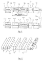
- FIG. 1 is a block diagram of a transmission chain and reception of a system implementing the COFDM technique. Characteristics of this broadcasting system are described in particular in the article “Principles modulation and channel coding in digital broadcasting to mobiles " already cited.
- the COFDM digital broadcasting system is based on the use combination of a channel coding device and a modulation method by multiplexing of orthogonal frequencies.
- Channel coding implements a convolutional code.
- the actual modulation process of this known system makes it possible to get rid of the problems linked to the frequency selectivity of the channel. It consists of ensuring the distribution of digital elements constituting the data signal in frequency-time space and to simultaneously emit sets of elements digital on a plurality of parallel broadcasting channels by means of a frequency multiplex using orthogonal carriers. In particular, this type modulation prevents two successive elements of the data train are issued at the same frequency.
- the source digital data 11 to be transmitted are subjected to a convolutional coding 12.
- the general principle of such a code is to associate with each source value a coded value dependent on this source value and at least one of the values that precedes it. Because of the link thus created between the coded values, it is then possible, during decoding, to reconstruct the sequence of source values even when a received coded value is false, using maximum decoding likelihood, such as a soft decision Viterbi decoding (i.e. a decoding delivering an estimate of the value received and a weighting representative of the confidence that can be placed in this estimate).
- a soft decision Viterbi decoding i.e. a decoding delivering an estimate of the value received and a weighting representative of the confidence that can be placed in this estimate.
- an external code of the Reed-Solomon or CSRS type (Cyclotomatically Shortened Reed Solomon (cyclotomatically Reed Solomon code shortcut)) can be concatenated to the convolutional code.
- Source data can of course be of any type, whether it's sound signals, image signals or data signals. They can no longer correspond to several sources of distinct origins, issued simultaneously.
- patent application FR 90 16383 filed on 19.12.1990 at name of the same applicants proposes a data organization in frames and in channels allowing in particular the simultaneous transmission of several sound channels (corresponding for example to the stereophonic channels of several radio stations), still or moving pictures, type information teletext, paging signals, etc.
- the COFDM system is based on the use of a plurality of carrier frequencies transmitted simultaneously.
- the number N of carriers can be arbitrary. It is conventionally of the order of a few hundred (it could also be on the order of a few units).
- Each of these carriers is modulated at a low rate (compared to the rate necessary for a corresponding single carrier system). This reduces the channel selectivity effect.
- the global signal transmitted is therefore a broadband signal (occupying for example a band of a few megahertz).
- This wide band is an advantage in the case of systems designed to take advantage of multiple paths, such as COFDM. Indeed, due to the spread of the response of the transmission channel, it is very unlikely that a fainting deep simultaneously affects the entire signal.
- the spectra of the different carriers overlap mutually.
- the complete signal satisfies certain orthogonality conditions, allowing the separation of the information associated with the different carriers, for example using the Fourier transformation technique (as well as this is specified below).
- orthogonality of carrier frequencies implies that the carrier spectra can be overlap, provided that when one of the spectra exhibits its power maximum, i.e. at the precise carrier frequency corresponding to this spectrum, all other spectra have zero power. Decoding is therefore not disturbed if we consider this precise frequency.
- Intersymbol interference introduced in particular by multiple paths during transmission can weaken this orthogonality.
- a guard interval is inserted (during which no decoding is carried out) between each symbol issued.
- the duration of this guard interval is chosen greater than the spread of the impulse response of the channel.
- the coding module 12 delivers coded data elements C k 13 belonging to a modulation alphabet.
- the choice of the alphabet specifies the type of modulation used. For example, for a modulation with 4 phase states (MDP4), the alphabet used is ⁇ 1 + i, 1 - i, -1 + i, -1 - i ⁇ .
- MDP4 modulation with 4 phase states
- the alphabet used is ⁇ 1 + i, 1 - i, -1 + i, -1 - i ⁇ .
- Many other types of modulation can be used, such as MDP8, 16QAM modulations or trellis coding modulations according to the Ungerboeck method.
- the coded data elements 13 are then subjected to an operation 14 of distribution in the space frequency-time, which consists in associating with each of the carrier frequencies of the data elements selected below data coded 13 so as to break, by mixing, the correlation of the distortions undergone by the transmitted samples.
- time-frequency space we mean a set of points distributed along two perpendicular axes, the time axis and the frequency axis. According to the frequency axis, there are as many points as there are carrier frequencies. According to the time axis, a point corresponds to the duration of a symbol.
- this distribution ensures at least that two source data are not transmitted consecutively and / or on the same carrier frequency. More generally, the distance in time-frequency space between two successive coded data is at least such that independence statistics between these data is ensured.
- this distribution 14 in time-frequency space may correspond to an interleaving in time 14 A consisting for example of a selective application of delays of different durations, followed by an interleaving in frequencies 14 B , consisting of an assignment selective data elements delayed at different carriers.
- Each carrier frequency is then modulated by the sequence of data elements C k which is intended for it after the interleaving in time and in frequency 14.
- This modulation operation can be carried out by applying an inverse fast Fourier transformation. (FFT -1 ) 16 on the sequence 15 of interleaved data elements delivered by the module 14.
- the signal transmitted in a transmission channel 19 (generally presenting multiple paths) is received in a reception module 110, also classic.
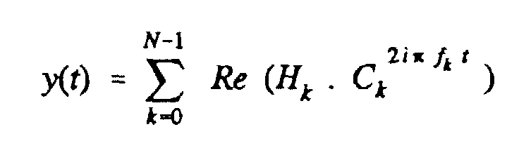
- each symbol received (not affected by intersymbol interference) can take the form: where H k represents the response of channel 19 at the frequency f k .
- This signal 111 is subjected to an inverse transformation (FFT -1 ) 112, symmetrical with the transformation 16.
- FFT -1 inverse transformation
- This transformation 112 delivers the following data 113:
- These data elements 115 are then subjected to a module of deinterlacing 116, performing the reverse operations of the module 14, so as to reconstruct the original order of the symbols, which are then directed in a module decoding 117, performing a posteriori maximum likelihood decoding, such as a soft decision Viterbi decoding.
- a module of deinterlacing 116 performing the reverse operations of the module 14, so as to reconstruct the original order of the symbols, which are then directed in a module decoding 117, performing a posteriori maximum likelihood decoding, such as a soft decision Viterbi decoding.
- the decoding module thus provides, after a possible decoding of the code concatenated, if such a code has been implemented on transmission, the corresponding signal 118 source signal 11.
- FIG. 2 illustrates a frame made up of M symbols successive.
- Each frame advantageously begins with three particular symbols S1, S2 and S3 whose role is explained below. Then it includes a certain number of useful symbols S4 to SM, each comprising N orthogonal carriers modulated 21.
- the symbol S1 is a null symbol, allowing on the one hand to carry out a analog synchronization, and secondly to perform spectral analysis of the channel broadcast.
- the symbol S2 is a second synchronization symbol consisting of an unmodulated multiplex of all carrier frequencies, with envelope substantially constant. It allows to synchronize the synchronization more precisely by analysis of the impulse response of the channel.
- the role and the mode of realization of these symbols S1 and S2 are described in patent FR 88 15216, filed on 18.11.88, on behalf of the same depositors.
- the S3 symbol is a sweeping symbol, giving a phase reference for the demodulation of each carrier of the following symbols, when these are modulated differently.
- the frame can also be cut into channels (Ci, Cj) grouping for example a variable number of symbols.
- each symbol begins with a guard interval 22, during which no decoding is performed. It eliminates orthogonality losses due to intersymbol interference.
- the COFDM system is designed to operate in the presence of multiple paths. This advantageous feature allows the implementation of single frequency broadcasting networks (in concerns the signal transmission frequency).
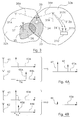
- FIG 3 illustrates, schematically, the principle of such single frequency networks.
- two transmitters 31 A and 31 B are shown , having respectively a geographical coverage 32 A and 32 B.
- the number of transmitters is much greater, and chosen to cover a given territory.
- these covers 32 A and 32 B have an overlap area 33, in which the signals transmitted by the two transmitters 31 A and 31 B can be received by a receiver 34.
- each transmitter In the broadcasting systems currently implemented, each transmitter must have a separate transmission frequency. Otherwise, the two signals received simultaneously by the receiver 34 combine in a non-interpretable manner.
- the receiver 34 interprets the contributions 38 A and 38 B of the two transmitters 31 A and 31 B received on its antenna 39 as natural echoes, from which it knows how to take advantage.
- the two contributions 38 A and 38 B correspond, according to the terminology used in the present application, to two separate transmission channels.
- a gray area is a geographic area 35 included in a territory 32, normally covered by a given transmitter 31 A , and in which no signal is received. For example, it may be an area hidden by the presence of a building.
- a cochannel re-transmitter 36 which includes a reception antenna 37 (placed outside the shaded area) and means of direct amplification on the same frequency of the received signal, covering the area shade.
- FIG. 3 shows the case of a receiver 310 equipped with two separate reception antennas 311 C and 311 D. Even when such a receiver is located in a geographical area covered by a single transmitter 31 B , it receives two distinct contributions 312 C and 312 D , on the antennas 311 C and 311 D respectively. These two contributions correspond to two reception channels, and are interpreted in the receiver, after combination, as natural echoes.
- each of the signals carried by one of the transmission or reception channels is of course subject to natural echoes.
- the signal combined in a receiver is therefore the combination of several corresponding signals natural echoes and / or active echoes.
- FIGS. 4A and 4B respectively present two reception situations corresponding to the reception of signals from two transmitters (corresponding to two transmission channels 41 and 42) or received on two reception antennas (corresponding two reception channels).
- the receiver therefore receives the contributions 43 A and 44 A corresponding to two distinct channels 41 and 42.
- the curve 45 A illustrates the combination of these two contributions.
- Component 46 A is received by channel 42 with a delay T A relative to channel 41.
- This delay T A being greater than the resolution capacity in time T R of the receiver, that is to say the capacity of discrimination between two components, the resultant 45 A comprises two distinct components 47 and 48 of which the receiver will perform a power addition (hence the advantage of the presence of multiple paths).
- the component 46 B is received on channel 42 with a very slight delay T B with respect to channel 41. If this delay T B is less than the resolution capacity in time T R , the resultant 45 B comprises only one component 49 corresponding to the addition of the two components of the channels 43 B and 44 B.
- the problem of fainting is not crucial.
- the reception conditions are constantly changing, due to variations in the characteristics of the transmission channel.
- the routes taken into account and the delays between these routes vary continuously. Consequently, a fainting situation is only punctual. This characteristic is known under the name of diversity in time.
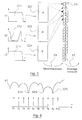
- Figure 5 shows how these point fades are fought in the COFDM system, thanks to interlacing and convolutional coding.
- Figure 6 illustrates the most likely case of a channel with selective fading.
- a signal consisting of ten carriers f 1 to f 10 is shown , transmitted in an invariant channel (due to the immobility of the receiver) illustrated by its transfer function 61.
- This transfer function has three fades 62 1 , 62 B and 62 C respectively affecting the carriers f 4 , f 7 and f 9 . Unlike the case of mobiles, where such fading is only punctual, in time, these carriers f 4 , f 7 and f 9 will always be affected, and can therefore never be decoded.
- the deinterlacing mechanism provides for successively reading these three carriers (for example, if the deinterlacing path is: instant t 1 : reading of f 9 ; instant t 2 : reading of f 4 ; instant t 3 : reading of f 7 ) , the maximum likelihood decoding device may be faulty. This situation is all the more disturbing as this situation will arise at regular intervals.
- the invention provides a solution to this problem of fixed receivers. More specifically, the invention responds to the following problem: how to benefit still receivers of time diversity benefits?
- the phenomenon of time diversity has been analyzed from a new angle, so that fixed receivers can also exploit it.
- diversity in time is due to the fact that journeys taken into account by mobile receivers have characteristics continuously varying.
- the problem therefore comes down to ensuring that the receivers receive also signals transmitted according to the paths which vary in time. In in other words, it is necessary to simulate a displacement of the fixed receiver.
- the channels subject to these modifications of "active generation" of time diversity can be located in multiple locations of the transmission chain. More specifically, they may be pathways each corresponding to a transmitting antenna or a transmitter separate, or reception channels, corresponding to as many reception antennas.
- Figures 7 and 10 thus present two examples of implementations corresponding to emission channels
- Figures 13 and 14 are two examples corresponding to reception channels.
- the time diversity generation processing can therefore be carried out at the level of the transmitters.
- the fixed receiver 34 placed in the overlap zone 33 will reconstruct a signal with variable characteristics, very similar to the signal it would receive if it moved. In other words, the modifications induced on the broadcast artificially generate time diversity.
- the principle of the invention is obviously only used in areas geographic areas 33, 35 where at least two independent signals, corresponding to separate antennas (or channels) are likely to be received simultaneously. In practical, this does not pose any particular problem, since these cases are the most frequent, and when a single signal is received, the receiver is close to the corresponding transmitter. The power received is then strong, and the risks fainting are therefore very low.
- the invention can also be implemented at the level of a single transmitter, since this transmitter comprises several transmitting antennas. If these transmit antennas transmit in different directions, fixed receivers will benefit from the advantages of the invention in areas where the emission fields antennas overlap.
- the same transmitter can also have at least two transmitting antennas transmitting in identical directions, so that it is possible to benefit from diversity in time actively generated according to the invention over the entire coverage area of this transmitter.
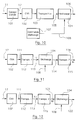
- FIG. 7 shows a first embodiment of means of generation of time diversity according to the invention, consisting in delaying so variable over time the symbols intended to be issued. Seen from a fixed receiver, the received signal will have more or less delay, in the same way as when the duration of a trip varies for a mobile receiver.
- these means 71 are inserted between the Fourier transformation 16, which delivers the symbols 17, and the transmission means 18. However, they can be found in many other places in the transmission chain, from the convolutional coding module 12 to the module 18. The signal can indeed be delayed at any time during its processing.
- the means 71 for applying a delay are controlled by means 72 of control of the duration of the delay, which regularly vary this duration. This variation can follow a deterministic function, from the moment it is independent from one transmitter to another. However, it will advantageously follow a random function, allowing easy independence between transmitters and avoiding that certain unfavorable situations arise regularly.
- the variation of the delays can consist of a selection of a delay among a set of delays available. Two examples of digital processing of this type are described below, in relation to FIGS. 8 and 9. Analog processing can also be implemented, the delay then varying for example so continues, under the control of the control means 72.
- a first solution to this problem is to appeal to delays varying continuously and very slowly.
- a second solution, in case the symbols are organized in symbol frames, as illustrated in the figure 2, is to use a constant delay throughout the duration of a frame, at the start of each frame, during the transmission of the symbol of silence S1. There is then no differential demodulation problem, the symbol S3 carrying references of demodulation.
- the maximum duration D max of the delay is chosen so that this delay does not significantly disturb the transmitted signal, and in particular does not prevent the reconstruction of the source data when only signals corresponding to a single transmitter are received.
- this maximum duration D max is much less than the duration of a symbol.
- D max less than or equal to T s / 50, T s being the duration of a symbol.
- Table I gives, for information only, the values applicable in the case of the system defined within the framework of the European DAB project, for which three modes are provided.
- T S delay d Mode I 1.25 ms 0 ⁇ d ⁇ 25 ⁇ s Mode II 312.5 ⁇ s 0 ⁇ d ⁇ 6.25 ⁇ s Mode III 156.25 ⁇ s 0 ⁇ d ⁇ 3 ⁇ s
- FIG. 8 shows a first embodiment of the means 71 and 72 for applying and controlling the delay.
- the symbols 17 are presented at the entry of a shift register 81 comprising L cells 82 1 to 82 L.
- This register 81 is shifted at the rate of D max / L, D max being the maximum duration of the delay.
- L distinct delays are applicable, equal to kD max / L, k varying from 1 to L.
- the value L can for example be between 20 and 50.
- a module 83 for selecting one of the L cells 82 1 to 82 L delivers to the transmission means 18 the symbols 84 delayed by the corresponding duration.
- This module 83 is controlled, as has already been described, by the means 72 for controlling the delay, which for example delivers a number 85 drawn randomly between 1 and L at each new start of frame.
- FIG. 9 Another embodiment of the means 71 and 72 is illustrated in FIG. 9. It is based on the use of a random access memory (RAM) 91 of the conventional type, powered by the sampled symbols 92 at the rate D max / L, D max being the maximum duration of a delay and L the number of distinct delays desired.
- RAM random access memory
- the samples 92 are written sequentially in the memory 91 then reread with the desired delay, to provide the delayed symbols 93.
- the delay is controlled in a particularly simple way by the delay control means 72 which specifies at each sampling instant a write address 94 (for the input sample 92) and a read address 95 (for the delayed sample 99).
- the delay applied corresponds to the difference between the reading address 95 and writing address 94.
- the invention is not limited to the application of time delays variables. Indeed, several other techniques can be envisaged to generate the diversity in time. In particular, it is possible to use variable phase shifts of the modulated signal, as illustrated in Figure 10.
- FIG. 10 shows the general principle of this technique.
- the module 101 of COFDM coding corresponds substantially to the grouping of modules 12, 14 and 16 of figure 1. It classically associates with the source data 11 symbols 17.
- the modules 102 for digital / analog conversion and 103 for transposition in the field of radio frequencies correspond substantially as for the transmission module 18 of FIG. 1.
- a phase shift 104 is applied varying over time at signal 105 delivered by the transposition module 103, to produce the signal to transmit 106. This amounts to producing a signal whose carrier frequency varies widely slightly over time. Receivers can handle these variations as long as they are slow enough not to induce an excessive Doppler effect.
- phase shift therefore varies over the interval [0, 2 ⁇ ], under the control of a control signal 108 delivered by means 107 of phase shift control.
- This variation evolves at a maximum frequency f max equal to a few Hertz or tens of Hertz, so as not to regenerate an excessive Doppler effect.
- T S f max Mode I 1.25 ms 4 Hz Mode II 312.5 ⁇ s 16 Hz Mode III 156.25 ⁇ s 32 Hz
- the phase shift signal 108 is an analog signal varying regularly. It can be any deterministic signal, independent of a transmitter to the other, or a random signal, that is, in other words, a noise signal low frequency.
- variable phase shift according to the invention can be applied indifferently in intermediate frequency or in radio frequency, as illustrated in Figures 11 and 12 respectively.
- the signal 111 converted analogically by the converter 102 is therefore transposed into a signal in intermediate frequency 113 by a first transposition module 112, which is phase shifted according to the technique of the invention by the phase shift module 104 already described.
- the phase shifted signal 114 is then transposed into radio frequency by a second transposition module 115 which delivers the signal 116 intended to be transmitted.
- the signal 111 delivered by the converter 102 is also transposed into an intermediate frequency signal 113 by a first transposition module 112.
- This signal 113 is then directly transposed by a second transposition module 115 into a signal in radio frequency 121, which is subjected to the phase shift 104 of the invention, before being issued (122).
- the invention is not limited to the generation of diversity in time in transmitters. Similar means can indeed be used works directly in receivers, provided that these are equipped with minus two receiving antennas (this technique is conventionally used to benefit from the diversity of space).
- FIGs 13 and 14 schematically illustrate two embodiments of receivers according to the invention, respectively employing means substantially corresponding to the resources of the issuers presented in relation to Figures 10 and 7.
- the receiver is equipped with two reception antennas 131 A and 131 B , so that two independent reception channels 132 A and 132 B are taken into account by the receiver.
- this makes it possible to take advantage of the diversity of space (the transmission channel associated with each antenna being distinct, a gain is generally obtained on the energy balances).
- the signal 133 B received by the antenna 131 B is transmitted directly to an adder 134.
- the signal 133 A received by the antenna 131 A is subjected to a variable phase shift, by a phase shift module 135 similar to the module 104 already described in conjunction with FIG. 10, and controlled by a phase shift control module 136 (similar to module 107 in FIG. 10).
- the two channels 132 A and 132 B are then, conventionally, added by the adder 134, which delivers a resulting signal 137, demodulated and decoded in a conventional manner in the COFDM decoding module 138.
- the receiver also comprises two reception antennas 131 A and 131 B which each deliver the received signal 133 A and 133 B to a transposition module, respectively 141 A and 141 B , which transposes the signal received by radio frequencies in a signal 142 A , 142 B in baseband.
- the signal 142 A is then subjected to delays of variable duration, using a delay application module 143 similar to the module 71 of FIG. 7, controlled by a module 144 for controlling the duration of the similar delay. to module 72 of FIG. 7.
- the module 143 delivers a delayed signal 145, which is combined with the signal 142 B corresponding to the second antenna 131 B in a combiner 146.
- the combined signal 147 is then decoded in a conventional manner, in a module COFDM decoding 148.
- Figures 13 and 14 can of course be easily generalized to receivers comprising more than two antennas (the processing applied to the signal received by each antenna then being different and independent).
- the invention is not limited to the two techniques described above as examples (delays and phase shifts), but more generally concerns all the means aimed at artificially generating time diversity in a stationary receiver.
- the invention concerns all the broadcasting systems in which we can distinguish, transmission and / or reception, by two independent channels, and comprising means for generating time diversity, by processing specific of the signal carried by at least one of the channels, intended to vary the characteristics of this signal so that its combination in a place of reception fixed with a signal carried by another channel behaves like a signal received at across a time-varying transmission channel.
Landscapes
- Engineering & Computer Science (AREA)
- Signal Processing (AREA)
- Computer Networks & Wireless Communication (AREA)
- Radio Transmission System (AREA)
- Mobile Radio Communication Systems (AREA)
Description
système dans lequel un même signal source est susceptible d'être transmis à un récepteur par l'intermédiaire d'au moins deux antennes correspondant chacune à une voie de transmission, chacune desdites voies portant un signal représentatif dudit signal source, lesdits signaux représentatifs du signal source portés par lesdites voies étant ensuite combinés dans ledit récepteur afin de restituer un signal utile combiné unique correspondant audit signal source,
et dans lequel un module spécifique de traitement, dit module de génération de diversité en temps, est associé à au moins une desdites voies, ledit module induisant artificiellement une modification contrôlée et variable dans le temps du signal porté par ladite voie de façon que, pour un récepteur immobile dans l'espace, ledit signal utile combiné présente une réponse en fréquence variable dans le temps, ladite modification étant en outre telle qu'elle n'empêche pas de restituer un signal utile correspondant audit signal source dans un récepteur à partir du signal porté par une seule et quelconque desdites voies.
- la figure 1 est un schéma synoptique global d'un système de diffusion de signaux COFDM de type connu;
- la figure 2 illustre la structure du signal transmis dans le système de diffusion de la figure 1 ;
- la figure 3 est un exemple schématique d'un réseau de diffusion monofréquence à réémetteur cocanal, dans lequel les récepteurs sont susceptibles de recevoir des signaux émis par plusieurs sources ;
- les figures 4A et 4B présentent deux cas de réception de deux fréquences correspondant à deux trajets, selon que l'écart entre les deux composantes est supérieur ou inférieur à la capacité de résolution en temps du récepteur ;
- la figure 5 présente le principe de l'utilisation de la diversité en temps, pour compenser les évanouissements passagers du canal de transmission, à l'aide des techniques d'entrelacement en temps et de codage convolutif ;
- la figure 6 est un exemple de fonction de transfert de canal présentant une configuration de réception défavorable dans le cas d'un récepteur immobile, en l'absence des moyens de génération active de la diversité en temps selon l'invention ;
- la figure 7 illustre schématiquement un premier mode de réalisation des moyens de l'invention, à base d'application de retards de durée variable ;
- les figures 8 et 9 sont les schémas de deux exemples différents de mise en oeuvre du premier mode de réalisation de la figure 7, correspondant respectivement à l'utilisation d'un registre à décalage et à l'utilisation d'une mémoire vive ;
- la figure 10 présente schématiquement un second mode de réalisation des moyens de l'invention, consistant en l'application de déphasages variables au signal modulé ;
- les figures 11 et 12 sont deux exemples schématiques de mise en oeuvre du second mode de réalisation de la figure 10, correspondant respectivement à l'application d'un déphasage variable en fréquence intermédiaire et en radiofréquence;
- les figures 13 et 14 illustrent deux modes de réalisation de récepteurs à diversité en temps générée selon l'invention, mettant en oeuvre respectivement des moyens similaires à ceux présentés dans les figures 7 et 10.

- N :
- nombre de porteuses du multiplex de porteuses orthogonales ;
- f 0 :
- fréquence arbitraire ;
- C k :
- élément de l'alphabet de modulation.






| T S | retard d | |
| Mode I | 1,25 ms | 0 ≤ d ≤ 25 µs |
| Mode II | 312,5 µs | 0 ≤ d ≤ 6,25 µs |
| Mode III | 156,25 µs | 0 ≤ d ≤ 3 µs |
| T S | f max | |
| Mode I | 1,25 ms | 4 Hz |
| Mode II | 312,5 µs | 16 Hz |
| Mode III | 156,25 µs | 32 Hz |
Claims (23)
- Système de diffusion de signaux numériques comprenant au moins un émetteur (31A, 31B, 36) émettant vers au moins un récepteur immobile dans l'espace (34, 310), dans lequel un même signal source est susceptible d'être transmis à un récepteur immobile dans l'espace (34, 310) par l'intermédiaire d'au moins deux antennes (31A, 31B ; 311C, 311D) correspondant chacune à une voie de transmission (38A, 38B ; 312C, 312D), chacune desdites voies portant un signal représentatif dudit signal source, lesdits signaux représentatifs du signal source portés par lesdites voies étant ensuite combinés dans ledit récepteur (34, 310) afin de restituer un signal utile combiné unique correspondant audit signal source,
caractérisé en ce qu'un module spécifique de traitement (71 ; 104 ; 135 ; 143), dit module de génération de diversité en temps, est associé à au moins une desdites voies (38A, 38B ; 312C, 312D), ledit module (71 ; 104 ; 135 ; 143) induisant artificiellement une modification contrôlée et variable dans le temps du signal porté par ladite voie de façon que, pour un récepteur immobile dans l'espace, ledit signal utile combiné présente une réponse en fréquence variable dans le temps,
ladite modification étant en outre telle qu'elle n'empêche pas de restituer un signal utile correspondant audit signal source dans un récepteur à partir du signal porté par une seule et quelconque desdites voies (38A, 38B ; 312C, 312D). - Système de diffusion de signaux numériques comprenant au moins un émetteur (31A, 31B, 36) émettant vers au moins un récepteur immobile dans l'espace (34, 310), dans lequel un même signal source est transmis par l'intermédiaire d'au moins deux antennes d'émission (31A, 31B) émettant chacune le même signal modulé par une même fréquence de modulation et correspondant chacune à une voie d'émission (38A, 38B), chacune desdites voies portant un signal représentatif dudit signal source, et dans lequel un récepteur (34) est susceptible de recevoir simultanément des signaux portés par au moins deux voies d'émission (38A, 38B), lesdits signaux portés par lesdites voies d'émission étant ensuite combinés dans ledit récepteur (34) afin de restituer un signal utile combiné unique correspondant audit signal source,
caractérisé en ce qu'un module spécifique de traitement (71 ; 104), dit module de génération de diversité en temps, est associé à au moins une desdites voies d'émission (38A, 38B), ledit module (71 ; 104) induisant artificiellement une modification contrôlée et variable dans le temps du signal destiné à être porté par ladite voie d'émission de façon que, pour un récepteur immobile dans l'espace, ledit signal utile combiné présente une réponse en fréquence variable dans le temps,
ladite modification étant en outre telle qu'elle n'empêche pas de restituer un signal utile correspondant audit signal source dans un récepteur à partir du signal porté par une seule et quelconque desdites voies (38A, 38B). - Système de diffusion de signaux numériques comprenant au moins un émetteur (31A, 31B, 36) émettant vers au moins un récepteur immobile dans l'espace (34, 310), dans lequel au moins un desdits récepteurs (310) est associé à au moins deux antennes de réception (31lC, 311D), correspondant chacune à une voie de réception (312C, 312D), chacune desdites voies de réception portant un signal représentatif dudit signal source, lesdits signaux portés par chacune desdites voies de réception étant ensuite combinés dans ledit récepteur (310) afin de restituer un signal utile combiné unique correspondant audit signal source,
caractérisé en ce qu'un module spécifique de traitement (135 ; 143), dit module de génération de diversité en temps, est associé à au moins une desdites voies de réception (312C, 312D), ledit module (135 ; 143) induisant artificiellement une modification contrôlée et variable dans le temps du signal porté par ladite voie de réception de façon que, pour un récepteur immobile dans l'espace, ledit signal utile combiné présente une réponse en fréquence variable dans le temps,
ladite modification étant en outre telle qu'elle n'empêche pas de restituer un signal utile correspondant audit signal source dans un récepteur à partir du signal porté par une seule et quelconque desdites voies (312C, 312D). - Système selon l'une quelconque des revendications 1 à 3, caractérisé en ce que ledit module de génération de diversité en temps comprend des moyens (71 ; 81, 83 ; 91 ; 143) d'application d'un retard de durée variant dans le temps au signal porté par au moins une desdites voies (38A, 38B, 312C, 312D).
- Système selon la revendication 4, dans lequel ledit signal source est constitué de symboles de données successifs (17 ; 92), caractérisé en ce que lesdits moyens (71 ; 81, 83 ; 91 ; 143) d'application d'un retard agissent sur lesdits symboles de données (17 ; 92) pour délivrer des symboles de données sélectivement retardés (84 ; 93).
- Système selon l'une quelconque des revendications 4 ou 5, caractérisé en ce que la durée dudit retard varie de façon aléatoire.
- Système selon l'une quelconque des revendications 4 à 6, du type appliqué à la transmission de trames de symboles de données consécutifs, caractérisé en ce que la durée dudit retard est sensiblement constante sur la période d'une trame.
- Système selon la revendication 7, du type appliqué à la transmission de trames débutant chacune par un symbole nul, ne portant aucune information, caractérisé en ce que ladite durée du retard est modifiée pendant ledit symbole nul.
- Système selon l'une quelconque des revendications 4 à 8, dans lequel ledit signal source se présente sous la forme d'échantillons numériques successifs (17, 92) dans au moins une chaíne de traitement associé à au moins une desdites voies (38A, 38B, 312C, 312D),
caractérisé en ce que lesdits moyens (81, 91) d'application d'un retard de durée variable retardent sélectivement chacun desdits échantillons numériques. - Système selon la revendication 9, caractérisé en ce que lesdits moyens d'application d'un retard comprennent un registre à décalage (81) à L positions (821 à 82L) alimenté par une première série d'échantillons numériques consécutifs (17) et des moyens (83) de sélection de l'une des sorties dudit registre (81) parmi les L sorties correspondant à chacune desdites L positions (821 à 82L), délivrant une seconde série d'échantillons numériques sélectivement retardés (84), lesdits moyens (83) de sélection étant contrôlés par des moyens (72) de gestion de ladite durée du retard.
- Système selon la revendication 9, caractérisé en ce que lesdits moyens d'application d'un retard comprennent des moyens (91) de mémorisation d'une série d'échantillons numériques consécutifs (92) et des moyens (72) de contrôle de l'adressage desdits moyens (91) de mémorisation, de façon que la durée entre l'écriture et la lecture d'un échantillon soit variable.
- Système selon l'une quelconque des revendications 4 ou 5, caractérisé en ce que ledit retard a une durée continûment variable.
- Système selon l'une quelconque des revendications 4 à 12, caractérisé en ce que ladite durée du retard est sensiblement comprise entre 0 et Ts/50, Ts étant la durée de chacun des symboles constituant lesdits signaux numériques.
- Système selon l'une quelconque des revendications 1 à 13, caractérisé en ce que ledit module de génération de diversité en temps comprend des moyens (104, 135) d'application d'un déphasage variable aux signaux portés par au moins une desdites voies (38A, 38B, 312C, 312D).
- Système selon la revendication 14, caractérisé en ce que lesdits moyens (104, 135) d'application d'un déphasage comprennent des moyens de déphasage analogique sur l'intervalle [0,2 π] des signaux portés par au moins une desdites voies (38A, 38B, 312C, 312D), contrôlés par un signal (108) de contrôle du déphasage.
- Système selon la revendication 15, caractérisé en ce que ledit signal (108) de contrôle du déphasage est un signal de bruit basse fréquence.
- Système selon la revendication 16, dans lequel ledit signal source est constitué de symboles de données consécutifs, caractérisé en ce que ledit signal de bruit est limité à une fréquence maximale sensiblement inférieure ou égale à 5/(1000.Ts), Ts étant la durée de chacun desdits symboles de données.
- Système selon l'une quelconque des revendications 13 à 17, caractérisé en ce que lesdits moyens (104) d'application d'un déphasage variable agissent sur des signaux transposés en fréquence intermédiaire (113) et/ou en radio-fréquence (121).
- Système selon l'une quelconque des revendications 1 à 18, caractérisé en ce que ledit au moins un émetteur (31A, 31B, 36) comprend des moyens (12) de codage desdits signaux numériques délivrant une série d'éléments de données codés successifs (13) et des moyens (14) d'entrelacement en temps desdits éléments de données codés (13).
- Système selon l'une quelconque des revendications 1 à 19, caractérisé en ce que ledit au moins un émetteur (31A, 31B, 36) comprend des moyens (12) de codage desdits signaux numériques délivrant une série d'éléments de données codés successifs (13), des moyens (16) de modulation de chacune des fréquences porteuses d'une pluralité de fréquences porteuses orthogonales (24) émises simultanément et des moyens (14B) d'affectation sélective à chacune desdites fréquences porteuses d'un jeu distinct d'éléments de données codés extraits de ladite série d'éléments de données codés (13) de façon que lesdits éléments de données soient entrelacés en fréquence.
- Système selon l'une quelconque des revendications 1 à 20, caractérisé en ce que ledit au moins un émetteur (31A, 31B, 36) comprend des moyens (12) de codage desdits signaux numériques délivrant une série d'éléments de données codés (13), lesdits moyens (12) de codage mettant en oeuvre un code convolutif.
- Emetteur d'un système de diffusion de signaux numériques comprenant au moins un émetteur émettant vers au moins un récepteur immobile dans l'espace, caractérisé en ce qu'il comprend des moyens (18) d'émission de signaux sur au moins une voie d'émission (38A, 38B), et des moyens (71) de génération de diversité en temps induisant artificiellement une modification contrôlée et variable dans le temps du signal porté par au moins une desdites voies d'émission (38A, 38B).
- Récepteur immobile dans l'espace d'un système de diffusion de signaux numériques comprenant au moins un émetteur émettant vers au moins un récepteur immobile dans l'espace, du type associé à au moins deux antennes de réception (311C, 311D), correspondant chacune à une voie de réception (312C, 312D), caractérisé en ce qu'il comprend des moyens (135 ; 143) de génération de diversité en temps induisant une modification contrôlée et variable dans le temps du signal porté par au moins une desdites voies de réception.
Applications Claiming Priority (2)
| Application Number | Priority Date | Filing Date | Title |
|---|---|---|---|
| FR9211360A FR2696064B1 (fr) | 1992-09-18 | 1992-09-18 | Système de diffusion de signaux numériques à génération active de la diversité en temps, émetteur et récepteur correspondants. |
| FR9211360 | 1992-09-18 |
Publications (2)
| Publication Number | Publication Date |
|---|---|
| EP0588741A1 EP0588741A1 (fr) | 1994-03-23 |
| EP0588741B1 true EP0588741B1 (fr) | 1999-05-26 |
Family
ID=9433818
Family Applications (1)
| Application Number | Title | Priority Date | Filing Date |
|---|---|---|---|
| EP19930460028 Expired - Lifetime EP0588741B1 (fr) | 1992-09-18 | 1993-09-16 | Système de diffusion de signaux numériques à génération active de la diversité en temps, émetteur et récepteur correspondants |
Country Status (3)
| Country | Link |
|---|---|
| EP (1) | EP0588741B1 (fr) |
| DE (1) | DE69325061T2 (fr) |
| FR (1) | FR2696064B1 (fr) |
Families Citing this family (10)
| Publication number | Priority date | Publication date | Assignee | Title |
|---|---|---|---|---|
| DE4319694C2 (de) * | 1993-06-16 | 1999-10-21 | Detecon Gmbh | Verfahren zur Verbesserung der Funkversorgung von Mobiltelefonen in Mobilfunksystemen |
| AU3215695A (en) * | 1994-09-09 | 1996-03-27 | Motorola, Inc. | Diversity receiver with combiner for equalization and diversity transmitter with splitter and delay |
| JPH10247855A (ja) * | 1997-03-04 | 1998-09-14 | Sony Corp | 放送信号受信装置 |
| GB2326308B (en) | 1997-06-06 | 2002-06-26 | Nokia Mobile Phones Ltd | Method and apparatus for controlling time diversity in telephony |
| US6842487B1 (en) * | 2000-09-22 | 2005-01-11 | Telefonaktiebolaget Lm Ericsson (Publ) | Cyclic delay diversity for mitigating intersymbol interference in OFDM systems |
| JP3639521B2 (ja) * | 2000-11-10 | 2005-04-20 | 株式会社ケンウッド | ダイバーシティ受信機及び直交周波数分割多重信号受信方法 |
| DE10103400A1 (de) * | 2001-01-26 | 2002-08-14 | Bosch Gmbh Robert | Verfahren zur Audioserviceumschaltung bei einem Rundfunkempfänger |
| EP1520362A1 (fr) * | 2002-06-28 | 2005-04-06 | Micronas GmbH | Procede de transmission de signaux audio sans fil pour un systeme audio spatial |
| AU2003278468A1 (en) * | 2002-12-04 | 2004-06-23 | Koninklijke Philips Electronics N.V. | Delay diversity in a wireless communication system |
| US8577299B2 (en) | 2004-06-04 | 2013-11-05 | Qualcomm Incorporated | Wireless communication system with configurable cyclic prefix length |
-
1992
- 1992-09-18 FR FR9211360A patent/FR2696064B1/fr not_active Expired - Lifetime
-
1993
- 1993-09-16 DE DE1993625061 patent/DE69325061T2/de not_active Expired - Lifetime
- 1993-09-16 EP EP19930460028 patent/EP0588741B1/fr not_active Expired - Lifetime
Also Published As
| Publication number | Publication date |
|---|---|
| DE69325061D1 (de) | 1999-07-01 |
| EP0588741A1 (fr) | 1994-03-23 |
| DE69325061T2 (de) | 2000-02-24 |
| FR2696064A1 (fr) | 1994-03-25 |
| FR2696064B1 (fr) | 1994-11-18 |
Similar Documents
| Publication | Publication Date | Title |
|---|---|---|
| EP0820172B1 (fr) | Procédé de diffusion de données numériques entrelacées en temps et en fréquence, affectant une puissance supérieure aux éléments de référence, ainsi que l'émetteur correspondant | |
| EP1988656B1 (fr) | Décodage de symboles d'un signal répartis suivant des dimensions fréquentielle et temporelle | |
| EP0802656B1 (fr) | Procédé d'estimation de canal et récepteur correspondant | |
| EP1425891A1 (fr) | Signal multiporteuses, procede de poursuite d'un canal de transmission a partir d'un tel signal et dispositif pour sa mise en oeuvre | |
| EP2156590B1 (fr) | Émission et réception de signaux à porteuses multiples et spectre étalé | |
| FR2854020A1 (fr) | Procede de transmission de donnees radio mettant en oeuvre plusieurs motifs de pilotes distincts, procede de reception, systeme, mobile et station de base correspondants | |
| FR2851384A1 (fr) | Procede de transmission de donnees radio, signal, systeme et dispositifs correspondant. | |
| EP1391095B1 (fr) | Procede d'estimation de la fonction de transfert d'un canal de transmission d'un signal multiporteuse et recepteur correspondant | |
| EP0616445B1 (fr) | Système de radiocommunication numérique bidirectionnel multiporteuse, station mobile et station de base correspondantes | |
| EP0588741A1 (fr) | Système de diffusion de signaux numériques à génération active de la diversité en temps, émetteur et récepteur correspondants | |
| EP1878185B1 (fr) | Procédé de codage d'un signal multiporteuse de type OFDM/OQAM utilisant des symboles à valeurs complexes, signal, dispositifs et programmes d'ordinateur correspondants | |
| EP1770885A1 (fr) | Procédé et système de planification automatique de retards des temps d'émission des émetteurs d'un réseau de diffusion synchrone en temps et en fréquence | |
| EP1446927B1 (fr) | Estimation d'un canal de transmission avec des symboles pilotes repartis selon une structure maillee | |
| EP2179519B1 (fr) | Emission de signal par plusieurs antennes | |
| FR2697699A1 (fr) | Dispositif de réamplification d'un signal radiofréquence, notamment pour des applications domestiques, et systèmes de réception correspondant. | |
| FR2877786A1 (fr) | Procede de reception d'un signal multiporteuse mettant en oeuvre au moins deux estimations d'un canal de propagation et dispositif de reception correspondant | |
| EP0631406B1 (fr) | Signal numérique apte à être reçu par des récepteurs à démodulateur de signaux modulés en amplitude à bande latérale réduite, procédé de transmission, procédé de réception, dispositif de réception et utilisation correspondants | |
| Othman | Study of reception techniques for aeronautical telemetry modulations | |
| FR2854009A1 (fr) | Signal multiporteuse concu pour reduire les interferences cellulaires au sein d'un reseau de radiocommunication, procede de construction, procede de reception, recepteur et emetteur correspondants | |
| EP0998065A1 (fr) | Canal module d'acquisition et de poursuite pour un systeme de radiocommunications | |
| FR2829890A1 (fr) | Procede et systeme de diffusion d'informations sous forme numerique depuis un satellite | |
| EP2524446A1 (fr) | Procede de transmission d'un signal numerique pour un systeme distribue, produit programme et dispositif relais correspondants | |
| Jerbi | Non-coherent detection of continuous phase modulation for low earth orbit satellite IoT communications affected by Doppler shift | |
| FR3027175A1 (fr) | Procede pour fournir des donnees de paquets de donnees ais recus, dispositif et programme d'ordinateur a cet effet | |
| FR2702110A1 (fr) | Procédé de contrôle automatique de fréquence pour la réception de signaux multiporteuses, et récepteur correspondant. |
Legal Events
| Date | Code | Title | Description |
|---|---|---|---|
| PUAI | Public reference made under article 153(3) epc to a published international application that has entered the european phase |
Free format text: ORIGINAL CODE: 0009012 |
|
| AK | Designated contracting states |
Kind code of ref document: A1 Designated state(s): DE GB |
|
| 17P | Request for examination filed |
Effective date: 19940819 |
|
| 17Q | First examination report despatched |
Effective date: 19970422 |
|
| GRAG | Despatch of communication of intention to grant |
Free format text: ORIGINAL CODE: EPIDOS AGRA |
|
| GRAG | Despatch of communication of intention to grant |
Free format text: ORIGINAL CODE: EPIDOS AGRA |
|
| GRAH | Despatch of communication of intention to grant a patent |
Free format text: ORIGINAL CODE: EPIDOS IGRA |
|
| GRAH | Despatch of communication of intention to grant a patent |
Free format text: ORIGINAL CODE: EPIDOS IGRA |
|
| GRAA | (expected) grant |
Free format text: ORIGINAL CODE: 0009210 |
|
| AK | Designated contracting states |
Kind code of ref document: B1 Designated state(s): DE GB |
|
| REF | Corresponds to: |
Ref document number: 69325061 Country of ref document: DE Date of ref document: 19990701 |
|
| GBT | Gb: translation of ep patent filed (gb section 77(6)(a)/1977) |
Effective date: 19990722 |
|
| PLBE | No opposition filed within time limit |
Free format text: ORIGINAL CODE: 0009261 |
|
| STAA | Information on the status of an ep patent application or granted ep patent |
Free format text: STATUS: NO OPPOSITION FILED WITHIN TIME LIMIT |
|
| 26N | No opposition filed | ||
| REG | Reference to a national code |
Ref country code: GB Ref legal event code: IF02 |
|
| PGFP | Annual fee paid to national office [announced via postgrant information from national office to epo] |
Ref country code: GB Payment date: 20120828 Year of fee payment: 20 |
|
| PGFP | Annual fee paid to national office [announced via postgrant information from national office to epo] |
Ref country code: DE Payment date: 20120827 Year of fee payment: 20 |
|
| REG | Reference to a national code |
Ref country code: DE Ref legal event code: R071 Ref document number: 69325061 Country of ref document: DE |
|
| REG | Reference to a national code |
Ref country code: DE Ref legal event code: R071 Ref document number: 69325061 Country of ref document: DE |
|
| REG | Reference to a national code |
Ref country code: GB Ref legal event code: PE20 Expiry date: 20130915 |
|
| PG25 | Lapsed in a contracting state [announced via postgrant information from national office to epo] |
Ref country code: DE Free format text: LAPSE BECAUSE OF EXPIRATION OF PROTECTION Effective date: 20130917 |
|
| PG25 | Lapsed in a contracting state [announced via postgrant information from national office to epo] |
Ref country code: GB Free format text: LAPSE BECAUSE OF EXPIRATION OF PROTECTION Effective date: 20130915 |