EP0588529A2 - Fuse or circuit breaker status indicator - Google Patents
Fuse or circuit breaker status indicator Download PDFInfo
- Publication number
- EP0588529A2 EP0588529A2 EP93306905A EP93306905A EP0588529A2 EP 0588529 A2 EP0588529 A2 EP 0588529A2 EP 93306905 A EP93306905 A EP 93306905A EP 93306905 A EP93306905 A EP 93306905A EP 0588529 A2 EP0588529 A2 EP 0588529A2
- Authority
- EP
- European Patent Office
- Prior art keywords
- fuse
- circuit breaker
- led
- light source
- load
- Prior art date
- Legal status (The legal status is an assumption and is not a legal conclusion. Google has not performed a legal analysis and makes no representation as to the accuracy of the status listed.)
- Granted
Links
- 238000012544 monitoring process Methods 0.000 claims abstract description 4
- 238000012360 testing method Methods 0.000 abstract description 10
- 238000010586 diagram Methods 0.000 description 8
- 230000000007 visual effect Effects 0.000 description 4
- 230000000881 depressing effect Effects 0.000 description 3
- 238000002955 isolation Methods 0.000 description 3
- 238000012986 modification Methods 0.000 description 3
- 230000004048 modification Effects 0.000 description 3
- 238000007664 blowing Methods 0.000 description 2
- 230000000994 depressogenic effect Effects 0.000 description 1
- 238000005286 illumination Methods 0.000 description 1
- 238000012806 monitoring device Methods 0.000 description 1
- 230000011664 signaling Effects 0.000 description 1
Images


Classifications
-
- H—ELECTRICITY
- H02—GENERATION; CONVERSION OR DISTRIBUTION OF ELECTRIC POWER
- H02H—EMERGENCY PROTECTIVE CIRCUIT ARRANGEMENTS
- H02H3/00—Emergency protective circuit arrangements for automatic disconnection directly responsive to an undesired change from normal electric working condition with or without subsequent reconnection ; integrated protection
- H02H3/02—Details
- H02H3/04—Details with warning or supervision in addition to disconnection, e.g. for indicating that protective apparatus has functioned
- H02H3/046—Signalling the blowing of a fuse
-
- G—PHYSICS
- G05—CONTROLLING; REGULATING
- G05B—CONTROL OR REGULATING SYSTEMS IN GENERAL; FUNCTIONAL ELEMENTS OF SUCH SYSTEMS; MONITORING OR TESTING ARRANGEMENTS FOR SUCH SYSTEMS OR ELEMENTS
- G05B9/00—Safety arrangements
- G05B9/02—Safety arrangements electric
-
- H—ELECTRICITY
- H02—GENERATION; CONVERSION OR DISTRIBUTION OF ELECTRIC POWER
- H02H—EMERGENCY PROTECTIVE CIRCUIT ARRANGEMENTS
- H02H3/00—Emergency protective circuit arrangements for automatic disconnection directly responsive to an undesired change from normal electric working condition with or without subsequent reconnection ; integrated protection
- H02H3/02—Details
- H02H3/04—Details with warning or supervision in addition to disconnection, e.g. for indicating that protective apparatus has functioned
- H02H3/044—Checking correct functioning of protective arrangements, e.g. by simulating a fault
-
- H—ELECTRICITY
- H02—GENERATION; CONVERSION OR DISTRIBUTION OF ELECTRIC POWER
- H02H—EMERGENCY PROTECTIVE CIRCUIT ARRANGEMENTS
- H02H3/00—Emergency protective circuit arrangements for automatic disconnection directly responsive to an undesired change from normal electric working condition with or without subsequent reconnection ; integrated protection
- H02H3/08—Emergency protective circuit arrangements for automatic disconnection directly responsive to an undesired change from normal electric working condition with or without subsequent reconnection ; integrated protection responsive to excess current
- H02H3/087—Emergency protective circuit arrangements for automatic disconnection directly responsive to an undesired change from normal electric working condition with or without subsequent reconnection ; integrated protection responsive to excess current for dc applications
Definitions
- the invention relates to devices indicating the status of a fuse or circuit breaker and, more particularly, devices providing a visual or audible indication of such.
- Such fuse and/or circuit breaker status indicators must remain electrically isolated from the circuits being protected to ensure they do not affect the performance of the protected circuits.
- the indicators must not significantly compromise the isolation between the protected circuitry and the power source after a fuse has blown or a circuit breaker tripped.
- the indicators should be capable of being easily tested, while on-line, to determine if the particular alarm (i.e. a flag, LED, lamp, or audible signal) is operational. In electronic systems employing large numbers of such status indicators, it is often preferable to test all the indicators at once.
- Present circuit protection device status indicators fail to provide the desired degree of isolation from the protected circuity, maintain the isolation between the protected circuit and the power supply, and allow for the easy, simultaneous on-line testing of large numbers of indicators.
- a status indicator for monitoring a fuse or a circuit breaker, including triggering and alarm circuits that are optically isolated from each other, and which can be integrated into a fuse holder or circuit breaker housing. More particularly, a status indicator having an LED connected in series with a fuse or circuit breaker across a power source, and a phototransistor arrangement, connected across the power source, in series with an alarm circuit. The arrangement is configured so that as long as current flows through the fuse or circuit breaker, the LED produces light which causes the phototransistor to be maintained in a non-conducting state, and the status indicator to remain in a non-alarm state.
- FIG. 1 is a schematic diagram showing a particular embodiment of the invention (100) incorporated into an electrical system having a power supply (101), a load (102), and a fuse (103).
- normally-closed switch 104, LED 105, limiting resistor 106, and fuse 103 are serially connected between positive power supply line 107 and negative power supply line 108.
- Depletion-mode photo-MOS transistor (“phototransistor") 109, limiting resistor 110, and alarm LED 111 are serially connected between positive power supply line 107 and negative power supply line 108.
- Fuse 103 connects negative power supply line 108 and negative load supply line 112. Phototransistor 109 is optically coupled to LED 105.
- both LED 105 and phototransistor 109 can be contained in a single opto-isolator, such as the AQV414 solid-state relay, manufactured by Aromat Corporation of West- field, New Jersey.
- the components of the invention 105, 106, 109, 110, and 111 can be incorporated within a standard size fuse holder.
- fuse 103 fails (i.e., blows)
- current is prohibited from flowing through LED 105 and resistor 106, and as a result LED 105 is not illuminated.
- phototransistor 109 is placed in a conducting state, and current flows through limiting resistor 110 and alarm LED 111. This causes alarm LED 111 to illuminate and provide a visual indication that fuse 103 has blown.
- LED 105 can be momentarily darkened when fuse 103 is intact by depressing switch 104.
- the switch interrupts current flow through LED 105 and resistor 106 (without effecting the current supplied to the load), and causes LED 105 to be temporarily switched off.
- phototransistor 109 is momentarily placed in a conductive state, and alarm LED 111 illuminates (mimicking the indicator's response to a failed fuse).
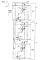
- FIG. 2 is a schematic diagram showing an electrical system including three fuse status indicators, 201, 202, and 203; each of which has a configuration similar to the indicator illustrated in FIG. 1.
- diodes 204, 205, and 206 have been incorporated to prevent a series connection from the load terminal of one fuse holder to the load terminal of another when switch 207 is depressed.
- the indicators are employed to monitor the status of fuses 208, 209, and 210, which protect three separate loads (211, 212, and 213 respectively).
- Each of the fuse status indicators operate in a manner similar to that of the indicator illustrated in FIG. 1. As shown in FIG.
- the current supplied to LEDs 214, 215, and 216 by power supply 217 can be interrupted via a single normally-closed switch (207), without effecting the current supplied to the loads.
- switch 207 By actuating switch 207, LEDs 214, 215, and 216 can be momentarily darkened when fuses 208, 209, and 210 are intact.
- phototransistors 218, 219, and 220 are momentarily placed in a conductive state, and alarm LEDs 221, 222, and 223 are simultaneously illuminated.
- FIG. 3 is a schematic diagram showing a particular embodiment of the invention (300) incorporated into an electrical system having a power supply (301), a load (302), and a fuse (303).
- normally-closed switch 304, LED 305, and limiting resistor 306 are serially connected between positive power supply line 307 and negative power input 308 of load 302.
- Enhancement-mode phototransistor 309, which is optically coupled to LED 305, is connected across LED 310.
- LED 310 and limiting resistor 311 are serially connected between positive power supply line 307 and negative power supply line 312.
- Enhancement- mode phototransistor 313, limiting resistor 314, and alarm LED 315 are serially connected between positive power supply line 307 and negative power supply line 312.
- Fuse 303 connects negative power supply line 312 and negative power input 308.
- Enhancement- mode phototransistor 313 is optically coupled to LED 310.
- the optically coupled LED and phototransistor pairs can each be contained in a single opto-isolator.
- the physical impact of employing the invention in pre-existing electrical systems can be minimized by incorporating the components of the invention (305, 306, 309, 310, 311, 313, 314, and 315) within a standard size fuse holder.
- fuse 303 fails (i.e., blows), current is prohibited from flowing through LED 305 and resistor 306, and as a result LED 305 is not illuminated. Without incident light from LED 305, phototransistor 309 is placed in a non-conducting state, allowing LED 310 to illuminate as a result of current flowing through limiting resistor 311. The light from LED 310 causes phototransistor 313 to allow current to flow through limiting resistor 314 and alarm LED 315. Alarm LED 315 illuminates to provide a visual indication that fuse 303 has blown.
- LED 305 can be momentarily darkened when fuse 303 is intact by depressing switch 304.
- the switch interrupts current flow through LED 305 nd resistor 306 (without effecting the current supplied to the load), and causes LED 305 to be temporarily switched off.
- phototransistor 309 is momentarily placed in a non-conductive state, LED 310 illuminates, causing phototransistor 313 to conduct, and alarm LED 315 to illuminate (mimicking the indicator's response to a failed fuse).
- FIG. 3 may be employed in an electrical system containing any number of fuse status indicators (in a configuration similar to the system illustrated in FIG. 2). Each of the indicators can be connected to a single switch to enable the simultaneous testing of multiple indicators.
- FIG. 4 is a schematic diagram showing a third embodiment of the invention (400) incorporated into an electrical system having a power supply (401) a load (402), a fuse (403) and an audible alarm bell (404).
- the operation of this embodiment is similar to that of the embodiment illustrated in FIG. 1 in that visual alarm LED 405 illuminates as a result of fuse 403 blowing.
- a second LED 406 (which may be an infrared emitting diode) also illuminates in response fuse 403 blowing.
- Phototransistor 407 which is optically coupled to LED 406, is placed in a conductive state as a result of the illumination of LED 406, allowing current to flow through bell 404 to produce an audible alarm signal.
- the indicator may be tested by depressing switch 408 which momentarily darkens LED 409 and causes LEDs 405 and 406 to illuminate.
- a second switch (410) is mechanically coupled to switch 408 so that bell 404 is prevented from sounding during the testing of the indicator.
- One such modification would include substituting an alternate signaling device (such as a lamp, an electromechanical flag, or an audible signal generator) for the alarm LED in any of the above described embodiments.
- Another such modification would include an indicator adapted to monitor a fuse serially connected to a positive power supply line.
- the invention could also be applied to monitor the status of a circuit breaker, or any other type of circuit element which changes from an electrically closed state to an electrically open state.
Abstract
Description
- The invention relates to devices indicating the status of a fuse or circuit breaker and, more particularly, devices providing a visual or audible indication of such.
- In electronic systems, individual circuit components are typically protected from short-circuiting and excessive currents by a fuse or a circuit breaker interposed between the component and a power supply. Large numbers of such protection devices may be found within any given system, depending upon the number of individual components contained therein. This has given rise to the need for fuse and circuit breaker status indicators which allow for the easy and rapid location of a tripped, failed or "blown" protection device within an electronic system. Typically, these indicators are incorporated into a fuse holder or circuit breaker housing, and trigger an alarm which serves to alert service personnel that a particular protection device has blown or tripped; the alarm can be an electromechanical flag, a light emitting diode ("LED"), a lamp, or an audible signal.
- Such fuse and/or circuit breaker status indicators must remain electrically isolated from the circuits being protected to ensure they do not affect the performance of the protected circuits. In addition, the indicators must not significantly compromise the isolation between the protected circuitry and the power source after a fuse has blown or a circuit breaker tripped. Furthermore, the indicators should be capable of being easily tested, while on-line, to determine if the particular alarm (i.e. a flag, LED, lamp, or audible signal) is operational. In electronic systems employing large numbers of such status indicators, it is often preferable to test all the indicators at once.
- Present circuit protection device status indicators fail to provide the desired degree of isolation from the protected circuity, maintain the isolation between the protected circuit and the power supply, and allow for the easy, simultaneous on-line testing of large numbers of indicators.
- The aforementioned problems are solved, in accordance with the principles of the invention, by providing a status indicator for monitoring a fuse or a circuit breaker, including triggering and alarm circuits that are optically isolated from each other, and which can be integrated into a fuse holder or circuit breaker housing. More particularly, a status indicator having an LED connected in series with a fuse or circuit breaker across a power source, and a phototransistor arrangement, connected across the power source, in series with an alarm circuit. The arrangement is configured so that as long as current flows through the fuse or circuit breaker, the LED produces light which causes the phototransistor to be maintained in a non-conducting state, and the status indicator to remain in a non-alarm state. Upon failure of the fuse or circuit breaker, currentflowtothe LED is interrupted, resulting in the phototransistor being biased into a conductive state, and the alarm circuit being activated. A normally closed switch is employed to interrupt the current flow to the LED, thereby simulating a fuse failure, and providing a convenient means forthe on-line testing the status indicator. Multiple LEDs, each associated with a separate monitored fuse or circuit breaker, can be connected to a single normally closed switch, thereby facilitating the simultaneous testing of numerous status indicators through the actuation of a single switch.
- In the drawing:
- FIG. 1 is a schematic diagram showing a particular embodiment of the invention incorporated into an electrical system having a power supply, a load, and a fuse;
- FIG. 2 is a schematic diagram showing an electrical system including three fuse status indicators, each of which has a configuration similar to the indicator illustrated in FIG. 1;
- FIG. 3 is a schematic diagram showing a second embodiment of the invention incorporated into an electrical system having a power supply, a load, and a fuse; and
- FIG. 4 is a schematic diagram showing a third embodiment of the invention incorporated into an electrical system having a power supply, a load, a fuse, and a bell.
- FIG. 1 is a schematic diagram showing a particular embodiment of the invention (100) incorporated into an electrical system having a power supply (101), a load (102), and a fuse (103). As shown, normally-closed
switch 104,LED 105, limitingresistor 106, andfuse 103 are serially connected between positivepower supply line 107 and negativepower supply line 108. Depletion-mode photo-MOS transistor ("phototransistor") 109, limitingresistor 110, andalarm LED 111 are serially connected between positivepower supply line 107 and negativepower supply line 108. Fuse 103 connects negativepower supply line 108 and negativeload supply line 112. Phototransistor 109 is optically coupled toLED 105. In practice, bothLED 105 andphototransistor 109 can be contained in a single opto-isolator, such as the AQV414 solid-state relay, manufactured by Aromat Corporation of West- field, New Jersey. In order to minimize the physical impact of employing the invention in pre-existing electrical systems, the components of the invention (105, 106, 109, 110, and 111) can be incorporated within a standard size fuse holder. - As long as
fuse 103 is intact, andswitch 104 is in a closed position, current flows throughLED 105, andresistor 106, thereby causingLED 105 to illuminate.Resistor 106 serves to limit the current passing throughLED 105. Light fromLED 105 causesphototransistor 109 to be placed in a non-conducting state, thereby prohibiting current from flowing through limitingresistor 110 andalarm LED 111. As a result,alarm LED 111 is not illuminated (an indication thatfuse 103 is intact). - If
fuse 103 fails (i.e., blows), current is prohibited from flowing throughLED 105 andresistor 106, and as aresult LED 105 is not illuminated. Withoutincident lightfrom LED 105,phototransistor 109 is placed in a conducting state, and current flows through limitingresistor 110 andalarm LED 111. This causesalarm LED 111 to illuminate and provide a visual indication thatfuse 103 has blown. - In order to testthe fuse indicator,
LED 105 can be momentarily darkened whenfuse 103 is intact by depressingswitch 104. The switch interrupts current flow throughLED 105 and resistor 106 (without effecting the current supplied to the load), and causesLED 105 to be temporarily switched off. In response,phototransistor 109 is momentarily placed in a conductive state, andalarm LED 111 illuminates (mimicking the indicator's response to a failed fuse). - FIG. 2 is a schematic diagram showing an electrical system including three fuse status indicators, 201, 202, and 203; each of which has a configuration similar to the indicator illustrated in FIG. 1. However,
diodes switch 207 is depressed. The indicators are employed to monitor the status offuses LEDs power supply 217 can be interrupted via a single normally-closed switch (207), without effecting the current supplied to the loads. By actuatingswitch 207,LEDs phototransistors alarm LEDs - Electrical systems incorporating any number of fuse status indicators may be configured similarly to the electrical system illustrated in FIG. 2., without any special wiring. Current can be supplied to each LED optically coupled to each phototransistorwithin the indicators via a single switch. The single switch enables the simultaneous testing of all fuse status indicators.
- FIG. 3 is a schematic diagram showing a particular embodiment of the invention (300) incorporated into an electrical system having a power supply (301), a load (302), and a fuse (303). As shown, normally-closed
switch 304,LED 305, and limitingresistor 306 are serially connected between positivepower supply line 307 andnegative power input 308 ofload 302. Enhancement-mode phototransistor 309, which is optically coupled toLED 305, is connected acrossLED 310.LED 310 and limitingresistor 311 are serially connected between positivepower supply line 307 and negativepower supply line 312. Enhancement-mode phototransistor 313, limitingresistor 314, andalarm LED 315 are serially connected between positivepower supply line 307 and negativepower supply line 312. Fuse 303 connects negativepower supply line 312 andnegative power input 308. Enhancement-mode phototransistor 313 is optically coupled toLED 310. As with the previously described embodiments, the optically coupled LED and phototransistor pairs can each be contained in a single opto-isolator. The physical impact of employing the invention in pre-existing electrical systems can be minimized by incorporating the components of the invention (305, 306, 309, 310, 311, 313, 314, and 315) within a standard size fuse holder. - As long as
fuse 303 is intact, andswitch 304 is in a closed position, current flows throughLED 305 andresistor 306, thereby causingLED 305 to illuminate. Light fromLED 305 causesphototransistor 109 to be placed in a conducting state, effectively shorting the leads ofLED 310 and thereby prohibitingLED 310 from illuminating. As a result,phototransistor 313 is placed in a non-conductive state, prohibiting current from flowing through limitingresistor 314 andalarm LED 315. As a result,alarm LED 315 is not illuminated (an indication that fuse 303 is intact). - If
fuse 303 fails (i.e., blows), current is prohibited from flowing throughLED 305 andresistor 306, and as aresult LED 305 is not illuminated. Without incident light fromLED 305,phototransistor 309 is placed in a non-conducting state, allowingLED 310 to illuminate as a result of current flowing through limitingresistor 311. The light fromLED 310 causes phototransistor 313 to allow current to flow through limitingresistor 314 andalarm LED 315.Alarm LED 315 illuminates to provide a visual indication that fuse 303 has blown. - To test the fuse indicator,
LED 305 can be momentarily darkened whenfuse 303 is intact by depressingswitch 304. The switch interrupts current flow throughLED 305 nd resistor 306 (without effecting the current supplied to the load), and causesLED 305 to be temporarily switched off. In response,phototransistor 309 is momentarily placed in a non-conductive state,LED 310 illuminates, causingphototransistor 313 to conduct, and alarm LED 315 to illuminate (mimicking the indicator's response to a failed fuse). - The embodiment of the invention illustrated in FIG. 3 may be employed in an electrical system containing any number of fuse status indicators (in a configuration similar to the system illustrated in FIG. 2). Each of the indicators can be connected to a single switch to enable the simultaneous testing of multiple indicators.
- FIG. 4 is a schematic diagram showing a third embodiment of the invention (400) incorporated into an electrical system having a power supply (401) a load (402), a fuse (403) and an audible alarm bell (404). The operation of this embodiment is similar to that of the embodiment illustrated in FIG. 1 in that
visual alarm LED 405 illuminates as a result offuse 403 blowing. However, a second LED 406 (which may be an infrared emitting diode) also illuminates inresponse fuse 403 blowing.Phototransistor 407, which is optically coupled toLED 406, is placed in a conductive state as a result of the illumination ofLED 406, allowing current to flow throughbell 404 to produce an audible alarm signal. The indicator may be tested by depressingswitch 408 which momentarily darkens LED 409 and causesLEDs bell 404 is prevented from sounding during the testing of the indicator. - The above-described invention provides a simple, reliable, and practical fuse status monitoring device. It will be understood that the particular embodiments described are only illustrative of the principles of the present invention, and that various modifications could be made by those skilled in the art without departing from the scope and spirit of the present invention, which is limited only by the claims thatfollow.
- One such modification would include substituting an alternate signaling device (such as a lamp, an electromechanical flag, or an audible signal generator) for the alarm LED in any of the above described embodiments. Another such modification would include an indicator adapted to monitor a fuse serially connected to a positive power supply line. The invention could also be applied to monitor the status of a circuit breaker, or any other type of circuit element which changes from an electrically closed state to an electrically open state.
Claims (8)
Applications Claiming Priority (2)
| Application Number | Priority Date | Filing Date | Title |
|---|---|---|---|
| US07/942,878 US5343192A (en) | 1992-09-10 | 1992-09-10 | Fuse or circuit breaker status indicator |
| US942878 | 1992-09-10 |
Publications (3)
| Publication Number | Publication Date |
|---|---|
| EP0588529A2 true EP0588529A2 (en) | 1994-03-23 |
| EP0588529A3 EP0588529A3 (en) | 1995-06-14 |
| EP0588529B1 EP0588529B1 (en) | 1998-07-15 |
Family
ID=25478747
Family Applications (1)
| Application Number | Title | Priority Date | Filing Date |
|---|---|---|---|
| EP93306905A Expired - Lifetime EP0588529B1 (en) | 1992-09-10 | 1993-09-01 | Apparatus for monitoring the status of a circuit protection device |
Country Status (5)
| Country | Link |
|---|---|
| US (1) | US5343192A (en) |
| EP (1) | EP0588529B1 (en) |
| JP (1) | JP3135756B2 (en) |
| CA (1) | CA2101223C (en) |
| DE (1) | DE69319678T2 (en) |
Cited By (5)
| Publication number | Priority date | Publication date | Assignee | Title |
|---|---|---|---|---|
| EP1037234A2 (en) * | 1999-03-16 | 2000-09-20 | Sick Ag | Safety switching circuitry |
| GB2381676A (en) * | 2001-11-02 | 2003-05-07 | Paul Brown | Fuse status indicator employing at least one LED |
| US7804481B2 (en) * | 2006-06-23 | 2010-09-28 | Lg. Display Co., Ltd. | Light sensing circuit, backlight control apparatus having the same, and liquid crystal display device having the same |
| US8032260B2 (en) | 2005-11-30 | 2011-10-04 | General Electric Company | Method and system for controlling a power distribution system |
| EP4174507A4 (en) * | 2021-06-25 | 2024-02-28 | Lg Energy Solution Ltd | Battery state detection device and battery protection device |
Families Citing this family (42)
| Publication number | Priority date | Publication date | Assignee | Title |
|---|---|---|---|---|
| DE4313532B4 (en) * | 1993-04-24 | 2007-08-30 | Robert Bosch Gmbh | Method for checking an output stage |
| US5701118A (en) * | 1996-02-20 | 1997-12-23 | Hull; Harold L. | Blown fuse indicator circuit and fuse cap, including a method of use therefore |
| US5754113A (en) * | 1996-10-28 | 1998-05-19 | Eaton Corporation | Circuit monitor for plural electrical switching apparatus |
| JP3242849B2 (en) * | 1996-10-30 | 2001-12-25 | 矢崎総業株式会社 | High current fuse unit |
| US5874884A (en) * | 1997-07-21 | 1999-02-23 | Hull; Harold L. | Blown fuse indicator circuit including a light housing containing a light source and method of use |
| DE19800779B4 (en) * | 1998-01-12 | 2004-09-23 | Klaus Bruchmann | Fuse holder with integrated connection line for status indicators |
| US5986557A (en) * | 1998-03-10 | 1999-11-16 | Automatic Timing & Controls, Inc. | Three-phase fuse status indicator |
| JP3810212B2 (en) * | 1998-05-19 | 2006-08-16 | 矢崎総業株式会社 | Large current fuse with temperature detection function and assembly method thereof |
| US6342995B1 (en) | 2000-03-02 | 2002-01-29 | Instrument Transformers, Inc. | Lighted escutcheon plate for power distribution equipment |
| US6404609B1 (en) * | 2000-03-31 | 2002-06-11 | Micro Motion, Inc. | Circuit that reduces the numbers of components needed to transmit data from intrinsically safe to non-intrinsically safe circuits using opto-couplers |
| EP1170058A3 (en) * | 2000-07-07 | 2003-09-17 | Lechler GmbH & Co.KG | Spray nozzle for fan shaped sprays |
| US7148698B2 (en) * | 2001-09-20 | 2006-12-12 | Snap-On Incorporated | Fuse saving tester for fused circuit |
| US7109877B2 (en) * | 2003-07-28 | 2006-09-19 | Nikola Cuk | Fault monitoring apparatus and method |
| US7369029B2 (en) * | 2004-04-20 | 2008-05-06 | Cooper Technologies Company | Wireless communication fuse state indicator system and method |
| US8134445B2 (en) * | 2004-04-20 | 2012-03-13 | Cooper Technologies Company | RFID open fuse indicator, system, and method |
| TW200635164A (en) * | 2004-09-10 | 2006-10-01 | Cooper Technologies Co | System and method for circuit protector monitoring and management |
| US20070194942A1 (en) * | 2004-09-10 | 2007-08-23 | Darr Matthew R | Circuit protector monitoring assembly, system and method |
| US8169331B2 (en) * | 2004-09-10 | 2012-05-01 | Cooper Technologies Company | Circuit protector monitoring assembly |
| US7561017B2 (en) * | 2004-09-13 | 2009-07-14 | Cooper Technologies Company | Fusible switching disconnect modules and devices |
| US7535371B2 (en) * | 2006-06-09 | 2009-05-19 | Wenzhou Sansheng Electrical Co., Ltd. | Ground fault circuit interrupter with end-of-life protection |
| US20060087397A1 (en) * | 2004-10-26 | 2006-04-27 | Cooper Technologies Company | Fuse state indicating optical circuit and system |
| US20080048819A1 (en) * | 2005-05-05 | 2008-02-28 | Cooper Technologies Company | Modular Fuseholders With Wireless Communication Capabilities |
| US20070159746A1 (en) | 2005-12-30 | 2007-07-12 | General Electric Company | Centrally controlled protection systems having reduced energy let-through mode |
| US20100134306A1 (en) * | 2006-06-09 | 2010-06-03 | Wenzhou Sansheng Electric Co., Ltd. | Ground Fault Circuit Interrupter With End-Of-Life Indicator |
| US7683752B1 (en) | 2007-01-05 | 2010-03-23 | Huss Roy A | Fuse box system |
| US20110175699A1 (en) * | 2007-01-05 | 2011-07-21 | Roy Allen Huss | Fuse box system and method |
| US8395473B1 (en) | 2007-01-05 | 2013-03-12 | Hussco, NC, LLC | Fuse box system |
| US8134828B2 (en) * | 2010-01-21 | 2012-03-13 | Cooper Technologies Company | Configurable deadfront fusible panelboard |
| JP2011192972A (en) * | 2010-02-18 | 2011-09-29 | Oki Semiconductor Co Ltd | Substrate inter-terminal voltage sensing circuit |
| US8810991B2 (en) * | 2010-10-05 | 2014-08-19 | Rockwell Automation Technologies, Inc. | Safety isolation systems and methods for switching DC loads |
| US8503148B2 (en) | 2010-10-20 | 2013-08-06 | Schneider Electric USA, Inc. | Circuit breaker with fault indication and secondary power supply |
| US8675325B2 (en) | 2010-10-20 | 2014-03-18 | Schneider Electric USA, Inc. | Electronic circuit breaker with alternate mode of operation using auxiliary power source |
| US9099270B2 (en) * | 2011-05-23 | 2015-08-04 | Tlz Creative Solutions Llc | Pole mounted fuse cutout indicator |
| US8973519B2 (en) | 2011-08-12 | 2015-03-10 | Thomas & Betts International, Inc. | Recloser position indicator |
| CN102386040A (en) * | 2011-11-17 | 2012-03-21 | 韩春龙 | DC (direct current) power supply fuse sound-light reminding circuit |
| US9170293B2 (en) * | 2012-06-07 | 2015-10-27 | Cooper Technologies Company | Power line indicator accessory for fusible circuit protection device array |
| DE102012107525A1 (en) * | 2012-08-16 | 2014-02-20 | Phoenix Contact Gmbh & Co. Kg | Fuse failure display |
| AU2013402093B2 (en) | 2013-09-26 | 2018-08-09 | Schneider Electric USA, Inc. | Load center monitor with optical waveguide sheet |
| DE202015001518U1 (en) * | 2015-02-23 | 2015-05-28 | Feti Gül | Circuit arrangement for indicating the state of a fuse or electronic fuse in an electrical circuit. |
| DE202018107179U1 (en) * | 2018-12-14 | 2020-03-19 | Weidmüller Interface GmbH & Co. KG | Fuse circuit with an overcurrent fuse and a signal device |
| WO2020191651A1 (en) * | 2019-03-27 | 2020-10-01 | Suzhou Littelfuse Ovs Co., Ltd. | Fuse status diagnostic with and without load operability |
| RU199376U1 (en) * | 2019-12-26 | 2020-08-28 | Общество с ограниченной ответственностью "Газпром трансгаз Ухта" | FUSE INTEGRITY CONTROL DEVICE |
Citations (3)
| Publication number | Priority date | Publication date | Assignee | Title |
|---|---|---|---|---|
| DE2926409A1 (en) * | 1979-06-29 | 1981-01-08 | Rotaprint Gmbh | Overload protection circuit with optical coupling - has auxiliary section with LED coupled to phototransistor operating magnetic switch |
| EP0349929A2 (en) * | 1988-07-05 | 1990-01-10 | Mitsubishi Denki Kabushiki Kaisha | Switch with pre-alarm means |
| US4931778A (en) * | 1989-02-27 | 1990-06-05 | Teledyne Industries, Inc. | Circuitry for indicating the presence of an overload or short circuit in solid state relay circuits |
Family Cites Families (9)
| Publication number | Priority date | Publication date | Assignee | Title |
|---|---|---|---|---|
| US2317030A (en) * | 1939-07-21 | 1943-04-20 | Rca Corp | Fuse indicating system |
| JPS5552757U (en) * | 1978-10-04 | 1980-04-08 | ||
| US4382225A (en) * | 1981-01-21 | 1983-05-03 | Gte Products Corporation | Signal indicating fuse testing apparatus |
| US4554607A (en) * | 1982-09-29 | 1985-11-19 | Dana Corporation | Fuse loss indicating circuit |
| US4581674A (en) * | 1983-03-30 | 1986-04-08 | General Electric Company | Thermal fuse device for protecting electrical fixtures |
| USH248H (en) * | 1984-09-04 | 1987-04-07 | The United States Of America As Represented By The Secretary Of The Army | Fuse status indicator system |
| US4691197A (en) * | 1985-06-24 | 1987-09-01 | Eaton Corporation | Blown fuse indicator |
| US4857896A (en) * | 1987-10-19 | 1989-08-15 | Square D Company | Polyphase circuit fuse condition indicating device |
| US4969063A (en) * | 1989-05-16 | 1990-11-06 | Square D Company | Circuit breaker with status indicating lights |
-
1992
- 1992-09-10 US US07/942,878 patent/US5343192A/en not_active Expired - Lifetime
-
1993
- 1993-07-23 CA CA002101223A patent/CA2101223C/en not_active Expired - Fee Related
- 1993-09-01 DE DE69319678T patent/DE69319678T2/en not_active Expired - Fee Related
- 1993-09-01 EP EP93306905A patent/EP0588529B1/en not_active Expired - Lifetime
- 1993-09-09 JP JP05247279A patent/JP3135756B2/en not_active Expired - Fee Related
Patent Citations (3)
| Publication number | Priority date | Publication date | Assignee | Title |
|---|---|---|---|---|
| DE2926409A1 (en) * | 1979-06-29 | 1981-01-08 | Rotaprint Gmbh | Overload protection circuit with optical coupling - has auxiliary section with LED coupled to phototransistor operating magnetic switch |
| EP0349929A2 (en) * | 1988-07-05 | 1990-01-10 | Mitsubishi Denki Kabushiki Kaisha | Switch with pre-alarm means |
| US4931778A (en) * | 1989-02-27 | 1990-06-05 | Teledyne Industries, Inc. | Circuitry for indicating the presence of an overload or short circuit in solid state relay circuits |
Cited By (8)
| Publication number | Priority date | Publication date | Assignee | Title |
|---|---|---|---|---|
| EP1037234A2 (en) * | 1999-03-16 | 2000-09-20 | Sick Ag | Safety switching circuitry |
| EP1037234A3 (en) * | 1999-03-16 | 2003-04-02 | Sick Ag | Safety switching circuitry |
| GB2381676A (en) * | 2001-11-02 | 2003-05-07 | Paul Brown | Fuse status indicator employing at least one LED |
| US8032260B2 (en) | 2005-11-30 | 2011-10-04 | General Electric Company | Method and system for controlling a power distribution system |
| US7804481B2 (en) * | 2006-06-23 | 2010-09-28 | Lg. Display Co., Ltd. | Light sensing circuit, backlight control apparatus having the same, and liquid crystal display device having the same |
| US7961181B2 (en) | 2006-06-23 | 2011-06-14 | Lg Display Co., Ltd. | Light sensing circuit, backlight control apparatus having the same, and liquid crystal display device having the same |
| US8643592B2 (en) | 2006-06-23 | 2014-02-04 | Lg Display Co., Ltd. | Light sensing circuit, backlight control apparatus having the same, and liquid crystal display device having the same |
| EP4174507A4 (en) * | 2021-06-25 | 2024-02-28 | Lg Energy Solution Ltd | Battery state detection device and battery protection device |
Also Published As
| Publication number | Publication date |
|---|---|
| EP0588529B1 (en) | 1998-07-15 |
| JP3135756B2 (en) | 2001-02-19 |
| CA2101223C (en) | 1997-02-04 |
| US5343192A (en) | 1994-08-30 |
| EP0588529A3 (en) | 1995-06-14 |
| DE69319678T2 (en) | 1999-02-04 |
| DE69319678D1 (en) | 1998-08-20 |
| JPH06203735A (en) | 1994-07-22 |
| CA2101223A1 (en) | 1994-03-11 |
Similar Documents
| Publication | Publication Date | Title |
|---|---|---|
| US5343192A (en) | Fuse or circuit breaker status indicator | |
| USH248H (en) | Fuse status indicator system | |
| US4983955A (en) | Electric power supply circuit monitoring systems | |
| US3603973A (en) | Combination fire and burglar alarm system | |
| US5347418A (en) | Fuse blowout detector circuit | |
| KR920001213A (en) | Fault circuit detector with separate indicator | |
| US3924256A (en) | Burglar alarm switch | |
| US5387899A (en) | Alarm system with monitoring circuit for detecting a cut or short in a pair of wires | |
| US4274087A (en) | Annunciator monitor circuit | |
| US2934752A (en) | Multiple warning system with single reset switch | |
| EP0028471A1 (en) | Security equipment for providing indication of removal of objects from monitored locations | |
| US3719937A (en) | Failure detection circuit | |
| JPH07287043A (en) | Disconnection detector of signal lamp using light emitting diode | |
| US3939398A (en) | Indicator lamp circuit having feedback protection | |
| GB2069205A (en) | A device for use in an electrical circuit and comprising two separable parts | |
| US5034726A (en) | Portable ground fault detector | |
| US3952229A (en) | Display device having signal lamps | |
| US6639330B2 (en) | Transfer relay for computer based equipment | |
| GB2107140A (en) | Fault indicator for domestic electrical systems | |
| US4496941A (en) | Switch protection device | |
| JPH02501185A (en) | Devices for detecting malfunctions of electrical equipment | |
| US3657714A (en) | Ground eliminator system | |
| EP0054407B1 (en) | Load current protection circuit | |
| US3747093A (en) | Alarm circuit | |
| SU1277160A1 (en) | Multicell signalling device |
Legal Events
| Date | Code | Title | Description |
|---|---|---|---|
| PUAI | Public reference made under article 153(3) epc to a published international application that has entered the european phase |
Free format text: ORIGINAL CODE: 0009012 |
|
| AK | Designated contracting states |
Kind code of ref document: A2 Designated state(s): DE FR GB |
|
| RAP3 | Party data changed (applicant data changed or rights of an application transferred) |
Owner name: AT&T CORP. |
|
| PUAL | Search report despatched |
Free format text: ORIGINAL CODE: 0009013 |
|
| RHK1 | Main classification (correction) |
Ipc: H02H 3/04 |
|
| AK | Designated contracting states |
Kind code of ref document: A3 Designated state(s): DE FR GB |
|
| 17P | Request for examination filed |
Effective date: 19951129 |
|
| 17Q | First examination report despatched |
Effective date: 19960816 |
|
| GRAG | Despatch of communication of intention to grant |
Free format text: ORIGINAL CODE: EPIDOS AGRA |
|
| GRAG | Despatch of communication of intention to grant |
Free format text: ORIGINAL CODE: EPIDOS AGRA |
|
| GRAG | Despatch of communication of intention to grant |
Free format text: ORIGINAL CODE: EPIDOS AGRA |
|
| GRAH | Despatch of communication of intention to grant a patent |
Free format text: ORIGINAL CODE: EPIDOS IGRA |
|
| GRAH | Despatch of communication of intention to grant a patent |
Free format text: ORIGINAL CODE: EPIDOS IGRA |
|
| GRAA | (expected) grant |
Free format text: ORIGINAL CODE: 0009210 |
|
| AK | Designated contracting states |
Kind code of ref document: B1 Designated state(s): DE FR GB |
|
| REF | Corresponds to: |
Ref document number: 69319678 Country of ref document: DE Date of ref document: 19980820 |
|
| ET | Fr: translation filed | ||
| PLBE | No opposition filed within time limit |
Free format text: ORIGINAL CODE: 0009261 |
|
| STAA | Information on the status of an ep patent application or granted ep patent |
Free format text: STATUS: NO OPPOSITION FILED WITHIN TIME LIMIT |
|
| 26N | No opposition filed | ||
| PGFP | Annual fee paid to national office [announced via postgrant information from national office to epo] |
Ref country code: FR Payment date: 20010823 Year of fee payment: 9 |
|
| PGFP | Annual fee paid to national office [announced via postgrant information from national office to epo] |
Ref country code: GB Payment date: 20010828 Year of fee payment: 9 |
|
| REG | Reference to a national code |
Ref country code: GB Ref legal event code: IF02 |
|
| PG25 | Lapsed in a contracting state [announced via postgrant information from national office to epo] |
Ref country code: GB Free format text: LAPSE BECAUSE OF NON-PAYMENT OF DUE FEES Effective date: 20020901 |
|
| GBPC | Gb: european patent ceased through non-payment of renewal fee |
Effective date: 20020901 |
|
| PG25 | Lapsed in a contracting state [announced via postgrant information from national office to epo] |
Ref country code: FR Free format text: LAPSE BECAUSE OF NON-PAYMENT OF DUE FEES Effective date: 20030603 |
|
| REG | Reference to a national code |
Ref country code: FR Ref legal event code: ST |
|
| PGFP | Annual fee paid to national office [announced via postgrant information from national office to epo] |
Ref country code: DE Payment date: 20060824 Year of fee payment: 14 |
|
| PG25 | Lapsed in a contracting state [announced via postgrant information from national office to epo] |
Ref country code: DE Free format text: LAPSE BECAUSE OF NON-PAYMENT OF DUE FEES Effective date: 20080401 |