EP0588475A2 - Fuel injection device - Google Patents
Fuel injection device Download PDFInfo
- Publication number
- EP0588475A2 EP0588475A2 EP93305575A EP93305575A EP0588475A2 EP 0588475 A2 EP0588475 A2 EP 0588475A2 EP 93305575 A EP93305575 A EP 93305575A EP 93305575 A EP93305575 A EP 93305575A EP 0588475 A2 EP0588475 A2 EP 0588475A2
- Authority
- EP
- European Patent Office
- Prior art keywords
- valve
- fuel
- chamber
- armature
- valve body
- Prior art date
- Legal status (The legal status is an assumption and is not a legal conclusion. Google has not performed a legal analysis and makes no representation as to the accuracy of the status listed.)
- Granted
Links
Images




Classifications
-
- F—MECHANICAL ENGINEERING; LIGHTING; HEATING; WEAPONS; BLASTING
- F02—COMBUSTION ENGINES; HOT-GAS OR COMBUSTION-PRODUCT ENGINE PLANTS
- F02M—SUPPLYING COMBUSTION ENGINES IN GENERAL WITH COMBUSTIBLE MIXTURES OR CONSTITUENTS THEREOF
- F02M59/00—Pumps specially adapted for fuel-injection and not provided for in groups F02M39/00 -F02M57/00, e.g. rotary cylinder-block type of pumps
- F02M59/44—Details, components parts, or accessories not provided for in, or of interest apart from, the apparatus of groups F02M59/02 - F02M59/42; Pumps having transducers, e.g. to measure displacement of pump rack or piston
- F02M59/46—Valves
- F02M59/466—Electrically operated valves, e.g. using electromagnetic or piezoelectric operating means
-
- F—MECHANICAL ENGINEERING; LIGHTING; HEATING; WEAPONS; BLASTING
- F02—COMBUSTION ENGINES; HOT-GAS OR COMBUSTION-PRODUCT ENGINE PLANTS
- F02M—SUPPLYING COMBUSTION ENGINES IN GENERAL WITH COMBUSTIBLE MIXTURES OR CONSTITUENTS THEREOF
- F02M57/00—Fuel-injectors combined or associated with other devices
- F02M57/02—Injectors structurally combined with fuel-injection pumps
-
- F—MECHANICAL ENGINEERING; LIGHTING; HEATING; WEAPONS; BLASTING
- F02—COMBUSTION ENGINES; HOT-GAS OR COMBUSTION-PRODUCT ENGINE PLANTS
- F02M—SUPPLYING COMBUSTION ENGINES IN GENERAL WITH COMBUSTIBLE MIXTURES OR CONSTITUENTS THEREOF
- F02M59/00—Pumps specially adapted for fuel-injection and not provided for in groups F02M39/00 -F02M57/00, e.g. rotary cylinder-block type of pumps
- F02M59/20—Varying fuel delivery in quantity or timing
- F02M59/36—Varying fuel delivery in quantity or timing by variably-timed valves controlling fuel passages to pumping elements or overflow passages
- F02M59/366—Valves being actuated electrically
Definitions
- This invention pertains to an injection control device for a fuel injection pump of diesel engine, more specifically, to a device that controls an injection level by a solenoid valve installed between the high-pressure side and the low-pressure side in the pump.
- This type of injection control device which the applicant is now working on its further development, has a system, wherein a valve body of the solenoid valve and an armature coacting with the valve body are connected; a spill chamber for allowing the high-pressure fuel to leak is formed around the valve head; an armature chamber for accommodating the armature is formed around the armature; and inside or around the valve body, a passage connecting the spill chamber and the armature chamber is formed, maintaining the pressure balance between the spill chamber and the armature chamber.
- the valve body constituting the solenoid valve is, due to its constitution, inserted in different members of the front and of the rear of the valve seat, and a sliding unit is formed in the area where the insertion is made. Although there is some clearance in each sliding unit, there are cases when the centers of the holes wherein the valve slides in do not necessarily agree, in the front and the rear of the valve seat, since the valve body moves only in axial direction, due to an error in selecting the size of each constituent member of the solenoid valve, or an error in assembling these members. If, in this case, the gap between the hole centers is within the amount of the clearance, there will no problem. But, if the gap exceeds the amount of clearance, this can possibly prevent the smooth movement of the valve body.
- the present invention aims to offer a fuel injection device, wherein the transfer of high periodic pressure surge from the spill chamber to the armature chamber is prevented, while securing the connection passage for maintaining the pressure balance, for smooth movement of the valve body; thereby the corrosion or deformation of the solenoid, which can happen after some passage of time, can be reduced.
- an objective of the present invention is to offer a fuel-injection pump, wherein between the high-pressure side leading to the compressor and the low-pressure side, a solenoid valve is installed, to adjust the connection condition between the high-pressure side and the low-pressure side.
- This solenoid valve comprises a valve body which places its valve head together with its valve seat in the spill chamber connected to the aforementioned low-pressure side, and which is equipped with the sliding units in the front and in rear of the valve head; an armature which is connected to one end of the valve body and is accommodated in the armature chamber; a solenoid which moves the aforementioned armature so as to close the aforementioned valve body while the compression is in progress in the fuel injection pump; and a return spring that pushes the aforementioned valve body against the electromagnetic force of the solenoid.
- a passage connecting the aforementioned armature chamber and the balance chamberformed around the edge of the opposite side to the armature, and a rising-pressure preventing passage to prevent a rise in pressure in the aforementioned armature chamber are installed.
- This rising-pressure preventing passage for preventing the pressure rise in the armature chamber may be formed by adjusting the clearance of the sliding unit, or by making the clearance of the sliding unit between the valve body and the balance chamber larger than the clearance of the sliding unit between the valve body and the armature. Or it may be constituted so that the excessive high-pressure fuel that tries to leak via the sliding unit can leak, via a release passage, from the sliding unit between the valve and the armature, to the spill chamber, rather than the constitution wherein the clearance of the sliding unit is adjusted.
- the valve can smoothly move according to the electromagnetic force of the solenoid and the rebounding force of the return spring.
- the valve head remains apart from the valve seat by the force of the return spring, and the low-pressure fuel goes into the high-pressure side from the low-pressure side, to be supplied to the compressor of the fuel injection pump.
- the armature is pulled by the electromagnetic force of the solenoid, and the valve head is seated in the valve seat, by which the fuel in the compressor is compressed.
- connection passage In the end of injection, when the high-pressure fuel is returned from the high-pressure side to the low-pressure side, the connection passage is not connected directly to the spill chamber, but is connected, via the clearance of the sliding unit, to the spill chamber, and therefore the periodic high-pressure surge is not transferred to the armature chamber.
- the clearance of the sliding unit of the valve positioned between the valve head and the armature is ordinarily set small, to keep the leak of the high- pressure fuel to the armature chamber to a minimal level during the compression, but there is an apprehension that however small the clearance may be, the high-pressure fuel may leak via the gap to the armature chamber, causing the pressure in the armature chamber to gradually rise to an abnormally high level. Therefore, the pressure rise in the armature chamber is prevented by means of the rising-pressure preventing passage in this constitution.
- the rising-pressure preventing passage is constituted so as to make the clearance of the sliding unit between the valve head and the balance chamber larger than the clearance of the sliding unit between the valve head and the armature, the pressure is released, via the connection passage and the balance chamber, from the clearance of the sliding unit between the valve head and the balance chamber, to the spill chamber, even when the high-pressure fuel is leaked to the armature chamber, and therefore the pressure in the armature chamber will constantly be low.
- the rising-pressure preventing passage comprises a return passage that returns the excessive high-pressure fuel to the spill chamber from the sliding unit between the valve head and the armature
- the excessive fuel that tries to leak from the high-pressure side to the armature chamber, through the clearance of the sliding unit between the valve head and the armature goes into the return passage prior to reaching the armature chamber, and is returned to the low-pressure side, and therefore the pressure in the armature chamber will constantly be kept low.
- the fuel injection pump has a solenoid valve positioned between the high- pressure side leading to the compressor and the low pressure side, to adjust the connection condition between both sides, that the solenoid valve comprises a valve which is slidably inserted in different members in the front and in the rear of the valve seat, an armature secured to the valve body, a solenoid which attracts the aforementioned solenoid during the period of the electrical conduction, and a return spring which pushes the aforementioned valve body against the electromagnetic force of the solenoid, and that a play mechanism is made, in the area where the aforementioned different members for the valve to slide in are facing each other, to absorb a gap between the sliding holes of the aforementioned different members.
- the play mechanism may be composed by constituting the valve body by two members of valve body, and by connecting each member so as to be relatively variable in length direction, in the area where the two different members, in which the valve slides in, are facing each other, so that the axial center of the valve slides in are facing each other, so that the axial center of the valve body can be shifted in position, or it may by composed so that the sliding areas of the valve body members, where the valve is inserted and slides in, can be changed in length direction, in stead of adjusting the valve's axial center.
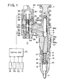
- Fig. 1 shows that the fuel-injection device has injection pump 1 of unit-injector type, which, for example injects a fuel into every cylinder of diesel engine.
- injection pump 1 of unit-injector type, which, for example injects a fuel into every cylinder of diesel engine.
- plunger 4 is slidably inserted in cylinder 3 formed on the base of plunger barrel 2
- compressor 5 is formed in the area which is surrounded by plunger barrel 2 and plunger 4.
- the aforementioned plunger 4 is constantly pushed away from plunger barrel 2 (upward direction in the figure) by spring 7 lying between tappet 6 connected to plunger 4 and plunger barrel 2.
- Tappet 6 contacts with a cam formed on the driving shaft of an engine not shown in the figure, and when the driving shaft rotates, tappet 6 coacts with the aforementioned spring 7 to reciprocate plunger 4.
- holder unit 8 To the end of plunger 4, holder unit 8 is secured, with holder nut 9, and to this holder unit 8, nozzle 11 is connected, with retaining nut 12 via spacer 10.
- spring case 13 On this holder unit 8, spring case 13 is formed, and by nozzle spring 14 accommodated in this spring case 13, a needle valve of the nozzle (not shown in the figure) is pressed in downward direction in the figure.
- nozzle 11 The structure of nozzle 11 is a well-known one, and when a high-pressure fuel having a pressure higher than a specific level is supplied, from compressor 5 located at the end of the plunger, to nozzle 11, via connection hole 16 formed in the plunger barrel, connection hole 17 made in holder 8, and connection hole 18 made in spacer 10, the needle valve is opened, to inject the fuel from the injection hole made in the tip of the nozzle.
- solenoid valve 20 Fuel supply to compressor 5 is adjusted by solenoid valve 20.
- This solenoid valve 20 is structured as follows, as shown in Fig. 2: valve body 22 is slidably inserted in sliding hole 19 of valve housing 21 installed on plunger barrel 2; valve seat 24 contacting with valve head 23 integrally built in valve body 22 is installed on valve housing 21; spill chamber 27 accommodating valve head 23 is formed between valve seat 24 and header 25 secured, with a screw, to valve housing 21 so as to cover valve head 23.
- Valve body 22 comprises a first valve body member 22a, on which valve head 23 is made, and a second valve body member 22b connected to this first valve body member 22b. More specifically, first valve body member 22a has a connecting piece 28 extending from valve head 23 to the header side, and this connecting piece 28 comprises a smaller diameter unit 28a formed to continue to valve header 23 and a larger diameter unit 28b integrally formed on the end of smaller diameter unit 28a. On the other hand, second valve member 22b has a joining cavity 29 made in the side.
- deep cavity 29b in which largerdiameter unit 28b is inserted, is formed to continue to shallow unit 29a which covers smaller diameter unit 28a, and larger diameter unit 28b ofjoin- ing piece 28 is engaged in joining cavity 29 in axial direction, while joining piece 28 is inserted in it in length direction with some room for play.
- First valve body member 22a penetrates holder 30 which is screwed to header 25 of valve housing 21 on its opposite side, and armature 31 is screwed in the end of member 22a.
- solenoid accommodating barrel 33 is attached, with holder nut 34, via spacer 32.
- the aforementioned armature 31 is accommodated in armature chamber 35 formed between holder 30 and spacer 32, and is facing solenoid 37 which is accommodated in solenoid barrel 33 via attaching hole 36 of spacer 32.
- This solenoid 37 is constituted by accommodating coil 39 in stator 38, and the end surface of stator 38 matches with that of spacer 32.
- spring case 41 is formed between holder 30 and spring receptacle 40 formed on the side of valve body 22, and in this spring case 41, return spring 42, which is constantly pushing valve head 23 away from valve seat 24, is accommodated. Therefore, only when electricity is conducted to solenoid 37, armature 31 is attracted to stator 38 against return spring 42, and valve head 23 is seated in valve seat 24.
- Second valve body member 22b is slidably inserted in insertion hole 43 made in header 25. Insertion hole 43 of header 25 is closed tightly by adjusting plug 44 from outside, and this adjusting plug 44 constitutes stopper45, so the maximum opening level of solenoid valve 20 can be regulated by adjusting screwing level of adjusting plug 44.
- valve body in the front and the rear of valve head 23, in other words, in the area where first valve body member 22a contacts with valve housing 21, and in the area where second valve body member 22b contacts with header 25, sliding units 46a, 46b are made, and the play mechanism is made to allow a relative gap between first valve body member 22a and second valve body 22b in length direction.
- loop-shaped channel 47 On the return spring side toward valve head 23 of valve body 22, loop-shaped channel 47 with a slightly smaller diameter is formed, and this loop-shaped channel 47 functions as a connecting groove to guide the fuel from one side to the other side between the high-pressure side and the low-pressure side when valve head 23 is apart from valve seat 24.
- Fuel supply passage 48 comprises fuel-intake 48a made in plunger barrel 2; intake passage 48b opened to loop-shaped groove 48c formed at the location where the groove's one end constantly faces the side surface of the plunger of cylinder 3; fuel-supply passage 48d which is opened, at its one end, to loop-shaped groove 48c and is connected to spill chamber 27 at its other end; and fuel-supply passage 48e which is, at its one end, connected to the aforementioned loop-shaped channel 47 and is opened to the aforementioned compressor 5 at its other end.
- passages 48b, 48d locate on the low-pressure side leading to fuel intake 48a
- passage 48e locates on the high-pressure side leading to compressor 5.
- the fuel flowing in from fuel-intake 48a is supplied from the low-pressure side to the high-pressure side, and is guided to compressor 5, when the plunger 4 is moving upward during the fuel- intake. Then, it is compressed in the compressor, and is injected from nozzle 11, once the valve head 23 is seated in valve seat 24, when the plunger 4 moves down during the compression. When valve head 23 moves away from valve seat 24 during the compression, the fuel on the high-pressure side leaks back to the low-pressure side via loop-shaped channel 47, and the injection is completed.
- the fuel outlet passage 52 is made in header 25, and this is connected to an overflow valve, not shown in the figure, to return the excessive low-pressure fuel to a fuel tank.
- Blind plug 53 plugs fuel supply passage 48e on the high-pressure side.
- balance chamber 55 is formed in the area surrounded by the aforementioned header 25, second valve member 22b, and by adjusting plug 44.
- Balance chamber 55 and armature chamber 35 are connected by connection passage 56.
- connection passage 56 comprises vertical through-hole 56a running through armature chamber 35, holder 30, valve housing 21, and header 25; horizontal through-hole 56b running through the side surface of the header 25 and balance chamber 55, and connected, at some point along the way, to the end of the vertical through-hole.
- the end opening of horizontal through-hole 56b is closed with blind plug 57 at the side surface of header.
- the clearance of sliding unit 46a between spill chamber 27 and armature chamber 35 is set smaller than that of sliding unit 46b between spill chamber 27 and balance chamber 55, to minimize the fuel leak from the high-pressure side to armature chamber 35 via the clearance of sliding unit 46a, deliberately allowing, at the same time, the fuel flow through the clearance of sliding unit 46b between spill chamber 27 and balance chamber 55, in spite of its high flow resistance, since a pressure-rise prevention passage is formed by the space of sliding unit 46b.
- the clearance of sliding unit 46a may be set, the leak of the excessive high-pressure fuel from the high-pressure side to armature 35 is unavoidable during the compression, when the solenoid valve seat 23 is seated in valve seat 23, and solenoid valve 20 is closed; therefore, the pressure in the armature chamber gradually tries to rise, but since the clearance of sliding unit 46b is set larger than that of sliding unit 46a, the pressure escapes from balance chamber 55 connected to armature chamber 35 via the connecting passage, to spill chamber 27, and the pressure does not rise in armature chamber 35.
- control unit 70 which comprises an A/D converter, multiplexer, microcomputer, memory, and driving circuit, and inputs the signals from rotation detector 71 detecting the rotation condi- i-tion of engine, acceleration level detector 72 detecting the degree at which accelerator is depressed (acceleration level), reference pulse generator 73 attached to a driving shaft and generating pulses at the shaft's every turning to the reference angle position, and from needle valve lift sensor 74 sensing the needle's lift timing. Based on these signals, the starting time and the ending time of conduction are computed, and the electrical conduction to solenoid valve 37 continues for the necessary time period, so that the valve- closed time length of solenoid valve 20 is controlled.
- control unit 70 which comprises an A/D converter, multiplexer, microcomputer, memory, and driving circuit, and inputs the signals from rotation detector 71 detecting the rotation condi- i-tion of engine, acceleration level detector 72 detecting the degree at which accelerator is depressed (acceleration level), reference pulse generator 73 attached to a driving shaft and generating
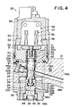
- Fig. 3 and Fig. 4 show other example of preferred embodiment of the present invention.
- the same number is assigned, and the explanation is below omitted; the explanation is given only for the different aspect.
- release passage 60 is formed, at some point along the sliding unit 46a between spill chamber 27 and armature chamber 35, to release the excessive high-pressure fuel that tries to leak through the sliding gap from the high-pressure side, and this release passage 60 constitutes the pressure-rise prevention passage.
- Various structures can be conceivable forthe release passage 60.
- loop-shaped groove 61 formed like a loop-shaped channel is made in the area facing the sliding unit 46a of valve housing 21, and release passage 60 is structured by connecting this loop-shaped groove 61 to spill chamber 27 via leakage hole 62.
- the aforementioned leakage hole 62 is made in valve body 22.
- Leakage hole 62 comprises horizontal through-hole 62a made in horizontal direction of first valve member 22a, to be opened to the aforementioned loop-shaped groove 61; vertical through-hole 62b, one end of which is opened to horizontal through-hole 62a, and other end of which is opened to joining cavity 29 connecting the end offirst valve member 22a and second valve member 22b. And, loop-shaped groove 61 and spill chamber 27 are connected likewise.
- valve 22 is, unlike the example of preferred embodiment, composed of one valve member, and if vertical through- hole 62b is structured so as to be opened to balance chamber 55, the aforementioned structure, wherein the clearance of sliding unit 46b between spill chamber 27 and balance chamber 55 would be necessary.
- header 25 to valve housing 21 of solenoid valve, for example, a screw is used, but unless precision is very high in attaching header 25, a gap will be created between the center lines of sliding holes 19, 43. If the gap is within the range of clearance of sliding units 46a, 46b, there would be no problem, but if the gap caused by an attaching error exceeds the amount of the clearance, excessive friction generates in sliding units 46a, 46b, possibly undercutting the smooth movement of valve 22.
- valve 22 comprises two valve body members, first valve member 22a and second valve member 22b, and first valve member 22a and second valve member 22b are allowed to be shifted in length direction relatively to each other; therefore, the gap in the axial center can be absorbed by valve body 22 without improving the precision level in attaching header 25, and there will not be a problem in the movement of valve 22.
- Fig. 5 shows another example of preferred embodiment of the present invention. As shown in the aforementioned examples, the same number is assigned to the component identical to that in the aforementioned examples and the explanation is omitted, except for the different aspect.
- valve 22 is composed of one member, and in this play structure, header 25 and valve housing 21 holds spacer 75 facing spill chamber 27, and valve body holder 76 is inserted in this spacer 75 with some room to play, in length direction. In sliding hole 43 of this valve body holder 76, the tip end of valve body 22 is slidably inserted.
- the play amount between valve body holder 76 and spacer 75 is determined, for example, by making the inner diameter of spacer 75 larger by 0.4 - 0.5 mm than the outer diameter of the insertion unit of valve body holder 76.
- the movement of this valve body holder 76 in axial direction is restricted by screw member 78 that screws ring-formed member via 77.
- stopper 79 facing the end of valve body 22 is secured with bolt 80, and by adjusting the screwing level of bolt 80, the position of stopper 79 can be adjusted in relation to that of screwing member 78 in axial direction.
- fuel outlet passage 52 is composed of multiple through-holes 81 made in the edge of spacer 75, and of opening 82 made in the center of header and connected to through-hole 81.
- vertical hole 84 is made, in the one end having valve head 23 through the other end connected to armature 31.
- This vertical hole 84 has, on its armature side, a screw hole to secure valve 22 to armature 31, and the hole is closed with screw 83 screwed in the center of armature 31.
- the clearance of sliding unit 46a between spill chamber 27 and armature 35 is set smaller than that of sliding unit 46b between spill chamber 27 and balance chamber 55, as with the case in the aforementioned example of preferred embodiment, so the rise of pressure in armature chamber 35 is prevented.
- the smooth movement of the valve body can be secured, without improving the precision in assembling every valve member.
- the present invention offers an advantage that since the higher precision in the assembling is not required, it allows the more simplified operation, and the reduction in labor.
Landscapes
- Engineering & Computer Science (AREA)
- Chemical & Material Sciences (AREA)
- Combustion & Propulsion (AREA)
- Mechanical Engineering (AREA)
- General Engineering & Computer Science (AREA)
- Physics & Mathematics (AREA)
- Electromagnetism (AREA)
- Fuel-Injection Apparatus (AREA)
Abstract
Description
- This invention pertains to an injection control device for a fuel injection pump of diesel engine, more specifically, to a device that controls an injection level by a solenoid valve installed between the high-pressure side and the low-pressure side in the pump.
- It is well known that there is a conventional injection control device wherein a solenoid valve is installed between the high-pressure side leading to the compressor and the low-pressure side leading to the fuel-intake in the fuel injection pump, and the high-pressure side and the low-pressure side are connected while the fuel-intake is in progress, to introduce the fuel into the compressor from the low-pressure side, whereas the connection between the high-pressure side and the low-pressure side are cut off while the compression is in progress, to inject the fuel from the compressor.
- This type of injection control device, which the applicant is now working on its further development, has a system, wherein a valve body of the solenoid valve and an armature coacting with the valve body are connected; a spill chamber for allowing the high-pressure fuel to leak is formed around the valve head; an armature chamber for accommodating the armature is formed around the armature; and inside or around the valve body, a passage connecting the spill chamber and the armature chamber is formed, maintaining the pressure balance between the spill chamber and the armature chamber.
- In the aforementioned technology, however, because the fuel spilled from the high-pressure side has very high pressure as high as 1500 kg/cm2, periodic high-pressure surge in spike form are transferred from the spill chamber to the armature chamber via the aforementioned connection passage, by the fuel momentarily leaked to the low-pressure side when the solenoid valve has been opened, circulating around the armature, and colliding with the solenoid surface, which, after some passage of time, may possibly cause the corrosion or deformation of a resin material covering the stator or coil, as shown in Fig. 6.
- The valve body constituting the solenoid valve is, due to its constitution, inserted in different members of the front and of the rear of the valve seat, and a sliding unit is formed in the area where the insertion is made. Although there is some clearance in each sliding unit, there are cases when the centers of the holes wherein the valve slides in do not necessarily agree, in the front and the rear of the valve seat, since the valve body moves only in axial direction, due to an error in selecting the size of each constituent member of the solenoid valve, or an error in assembling these members. If, in this case, the gap between the hole centers is within the amount of the clearance, there will no problem. But, if the gap exceeds the amount of clearance, this can possibly prevent the smooth movement of the valve body.
- To solve this problem, it can be considered that accuracy in assembling the valve constituent members should be improved to limit the gap between the hole centers within the amount of clearance, but this will require some means to assure accuracy in assembling and an additional process of work.
- Therefore, the present invention aims to offer a fuel injection device, wherein the transfer of high periodic pressure surge from the spill chamber to the armature chamber is prevented, while securing the connection passage for maintaining the pressure balance, for smooth movement of the valve body; thereby the corrosion or deformation of the solenoid, which can happen after some passage of time, can be reduced.
- Briefly speaking, an objective of the present invention is to offer a fuel-injection pump, wherein between the high-pressure side leading to the compressor and the low-pressure side, a solenoid valve is installed, to adjust the connection condition between the high-pressure side and the low-pressure side. This solenoid valve comprises a valve body which places its valve head together with its valve seat in the spill chamber connected to the aforementioned low-pressure side, and which is equipped with the sliding units in the front and in rear of the valve head; an armature which is connected to one end of the valve body and is accommodated in the armature chamber; a solenoid which moves the aforementioned armature so as to close the aforementioned valve body while the compression is in progress in the fuel injection pump; and a return spring that pushes the aforementioned valve body against the electromagnetic force of the solenoid. On the aforementioned solenoid valve, a passage connecting the aforementioned armature chamber and the balance chamberformed around the edge of the opposite side to the armature, and a rising-pressure preventing passage to prevent a rise in pressure in the aforementioned armature chamber are installed.
- This rising-pressure preventing passage for preventing the pressure rise in the armature chamber may be formed by adjusting the clearance of the sliding unit, or by making the clearance of the sliding unit between the valve body and the balance chamber larger than the clearance of the sliding unit between the valve body and the armature. Or it may be constituted so that the excessive high-pressure fuel that tries to leak via the sliding unit can leak, via a release passage, from the sliding unit between the valve and the armature, to the spill chamber, rather than the constitution wherein the clearance of the sliding unit is adjusted.
- Since an equal amount of the fuel flows, via the connection passage, to the armature side and to the edge of the opposite side to the armature, the valve can smoothly move according to the electromagnetic force of the solenoid and the rebounding force of the return spring. In other words, while the fuel-intake is in progress and electrical conduction is not taking place, the valve head remains apart from the valve seat by the force of the return spring, and the low-pressure fuel goes into the high-pressure side from the low-pressure side, to be supplied to the compressor of the fuel injection pump. While the fuel compression is in progress and the electrical conduction is taking place, the armature is pulled by the electromagnetic force of the solenoid, and the valve head is seated in the valve seat, by which the fuel in the compressor is compressed. In the end of injection, when the high-pressure fuel is returned from the high-pressure side to the low-pressure side, the connection passage is not connected directly to the spill chamber, but is connected, via the clearance of the sliding unit, to the spill chamber, and therefore the periodic high-pressure surge is not transferred to the armature chamber.
- In the aforementioned constitution, the clearance of the sliding unit of the valve positioned between the valve head and the armature is ordinarily set small, to keep the leak of the high- pressure fuel to the armature chamber to a minimal level during the compression, but there is an apprehension that however small the clearance may be, the high-pressure fuel may leak via the gap to the armature chamber, causing the pressure in the armature chamber to gradually rise to an abnormally high level. Therefore, the pressure rise in the armature chamber is prevented by means of the rising-pressure preventing passage in this constitution.
- If the rising-pressure preventing passage is constituted so as to make the clearance of the sliding unit between the valve head and the balance chamber larger than the clearance of the sliding unit between the valve head and the armature, the pressure is released, via the connection passage and the balance chamber, from the clearance of the sliding unit between the valve head and the balance chamber, to the spill chamber, even when the high-pressure fuel is leaked to the armature chamber, and therefore the pressure in the armature chamber will constantly be low.
- Furthermore, if the rising-pressure preventing passage comprises a return passage that returns the excessive high-pressure fuel to the spill chamber from the sliding unit between the valve head and the armature, the excessive fuel that tries to leak from the high-pressure side to the armature chamber, through the clearance of the sliding unit between the valve head and the armature, goes into the return passage prior to reaching the armature chamber, and is returned to the low-pressure side, and therefore the pressure in the armature chamber will constantly be kept low.
- Other objective of the present invention is that the fuel injection pump has a solenoid valve positioned between the high- pressure side leading to the compressor and the low pressure side, to adjust the connection condition between both sides, that the solenoid valve comprises a valve which is slidably inserted in different members in the front and in the rear of the valve seat, an armature secured to the valve body, a solenoid which attracts the aforementioned solenoid during the period of the electrical conduction, and a return spring which pushes the aforementioned valve body against the electromagnetic force of the solenoid, and that a play mechanism is made, in the area where the aforementioned different members for the valve to slide in are facing each other, to absorb a gap between the sliding holes of the aforementioned different members.
- The play mechanism may be composed by constituting the valve body by two members of valve body, and by connecting each member so as to be relatively variable in length direction, in the area where the two different members, in which the valve slides in, are facing each other, so that the axial center of the valve slides in are facing each other, so that the axial center of the valve body can be shifted in position, or it may by composed so that the sliding areas of the valve body members, where the valve is inserted and slides in, can be changed in length direction, in stead of adjusting the valve's axial center.
- Accordingly, in the past, there was an apprehension that due to an assembling error, which is made in assembling the members, in which the solenoid valve's valve body to slide in, the center line of the sliding hole could be displaced. But, according to this invention, smooth movement of the valve body can be secured without improving assembling precision, since the gap between the sliding holes, in which the valve slides, is absorbed by the play mechanism; therefore, the aforementioned objectives can be implemented.
- Fora better understanding of the invention and to show how the same may be carried into effect, reference will now be made, by way of example, to the accompanying drawings in which:
- Fig. 1 shows a schematic diagram of the preferred embodiment of the fuel-injection device.
- Fig. 2 shows an expanded sectional view of the solenoid valve of the fuel-injection device of Fig. 1.
- Fig. 3 shows an expanded sectional view of other example of preferred embodiment of the solenoid valve.
- Fig. 4 shows an expanded sectional view of another example of preferred embodiment of the solenoid valve.
- Fig. 5 shows an expanded sectional view of another example of preferred embodiment of the solenoid valve.
- Fig. 6 shows the test data illustrating the changes in pressure in the armature chamber of the solenoid valve.
- Preferred embodiments of the present invention are explained below in reference with the figures.
- Fig. 1 shows that the fuel-injection device has injection pump 1 of unit-injector type, which, for example injects a fuel into every cylinder of diesel engine. In this injection pump 1,
plunger 4 is slidably inserted incylinder 3 formed on the base ofplunger barrel 2, andcompressor 5 is formed in the area which is surrounded byplunger barrel 2 andplunger 4. Theaforementioned plunger 4 is constantly pushed away from plunger barrel 2 (upward direction in the figure) byspring 7 lying betweentappet 6 connected toplunger 4 andplunger barrel 2.Tappet 6 contacts with a cam formed on the driving shaft of an engine not shown in the figure, and when the driving shaft rotates, tappet 6 coacts with theaforementioned spring 7 to reciprocateplunger 4. - To the end of
plunger 4,holder unit 8 is secured, withholder nut 9, and to thisholder unit 8, nozzle 11 is connected, with retainingnut 12 viaspacer 10. On thisholder unit 8,spring case 13 is formed, and bynozzle spring 14 accommodated in thisspring case 13, a needle valve of the nozzle (not shown in the figure) is pressed in downward direction in the figure. The structure of nozzle 11 is a well-known one, and when a high-pressure fuel having a pressure higher than a specific level is supplied, fromcompressor 5 located at the end of the plunger, to nozzle 11, viaconnection hole 16 formed in the plunger barrel,connection hole 17 made inholder 8, andconnection hole 18 made inspacer 10, the needle valve is opened, to inject the fuel from the injection hole made in the tip of the nozzle. - Fuel supply to
compressor 5 is adjusted bysolenoid valve 20. Thissolenoid valve 20 is structured as follows, as shown in Fig. 2:valve body 22 is slidably inserted in slidinghole 19 ofvalve housing 21 installed onplunger barrel 2;valve seat 24 contacting withvalve head 23 integrally built invalve body 22 is installed onvalve housing 21;spill chamber 27accommodating valve head 23 is formed betweenvalve seat 24 andheader 25 secured, with a screw, tovalve housing 21 so as to covervalve head 23. - Valve
body 22 comprises a firstvalve body member 22a, on whichvalve head 23 is made, and a secondvalve body member 22b connected to this firstvalve body member 22b. More specifically, firstvalve body member 22a has a connectingpiece 28 extending fromvalve head 23 to the header side, and this connectingpiece 28 comprises asmaller diameter unit 28a formed to continue tovalve header 23 and alarger diameter unit 28b integrally formed on the end ofsmaller diameter unit 28a. On the other hand,second valve member 22b has a joiningcavity 29 made in the side. In this joiningcavity 29,deep cavity 29b, in whichlargerdiameter unit 28b is inserted, is formed to continue toshallow unit 29a which coverssmaller diameter unit 28a, andlarger diameter unit 28b ofjoin-ing piece 28 is engaged in joiningcavity 29 in axial direction, while joiningpiece 28 is inserted in it in length direction with some room for play. - First
valve body member 22a penetratesholder 30 which is screwed toheader 25 ofvalve housing 21 on its opposite side, andarmature 31 is screwed in the end ofmember 22a. To thisholder 30,solenoid accommodating barrel 33 is attached, withholder nut 34, viaspacer 32. Theaforementioned armature 31 is accommodated inarmature chamber 35 formed betweenholder 30 andspacer 32, and is facingsolenoid 37 which is accommodated insolenoid barrel 33 via attachinghole 36 ofspacer 32. Thissolenoid 37 is constituted byaccommodating coil 39 instator 38, and the end surface ofstator 38 matches with that ofspacer 32. In theaforementioned holder 30,spring case 41 is formed betweenholder 30 andspring receptacle 40 formed on the side ofvalve body 22, and in thisspring case 41, returnspring 42, which is constantly pushingvalve head 23 away fromvalve seat 24, is accommodated. Therefore, only when electricity is conducted tosolenoid 37,armature 31 is attracted tostator 38 againstreturn spring 42, andvalve head 23 is seated invalve seat 24. - Second
valve body member 22b is slidably inserted ininsertion hole 43 made inheader 25.Insertion hole 43 ofheader 25 is closed tightly by adjustingplug 44 from outside, and this adjustingplug 44 constitutes stopper45, so the maximum opening level ofsolenoid valve 20 can be regulated by adjusting screwing level of adjustingplug 44. - In the valve body, in the front and the rear of
valve head 23, in other words, in the area where firstvalve body member 22a contacts withvalve housing 21, and in the area where secondvalve body member 22b contacts withheader 25, slidingunits valve body member 22a andsecond valve body 22b in length direction. - On the return spring side toward
valve head 23 ofvalve body 22, loop-shaped channel 47 with a slightly smaller diameter is formed, and this loop-shaped channel 47 functions as a connecting groove to guide the fuel from one side to the other side between the high-pressure side and the low-pressure side whenvalve head 23 is apart fromvalve seat 24. -
Fuel supply passage 48 comprises fuel-intake 48a made inplunger barrel 2;intake passage 48b opened to loop-shaped groove 48c formed at the location where the groove's one end constantly faces the side surface of the plunger ofcylinder 3; fuel-supply passage 48d which is opened, at its one end, to loop-shaped groove 48c and is connected tospill chamber 27 at its other end; and fuel-supply passage 48e which is, at its one end, connected to the aforementioned loop-shaped channel 47 and is opened to theaforementioned compressor 5 at its other end. In theaforementioned solenoid valve 37,passages fuel intake 48a, andpassage 48e locates on the high-pressure side leading tocompressor 5. - The fuel flowing in from fuel-
intake 48a is supplied from the low-pressure side to the high-pressure side, and is guided tocompressor 5, when theplunger 4 is moving upward during the fuel- intake. Then, it is compressed in the compressor, and is injected from nozzle 11, once thevalve head 23 is seated invalve seat 24, when theplunger 4 moves down during the compression. Whenvalve head 23 moves away fromvalve seat 24 during the compression, the fuel on the high-pressure side leaks back to the low-pressure side via loop-shaped channel 47, and the injection is completed. - The
fuel outlet passage 52 is made inheader 25, and this is connected to an overflow valve, not shown in the figure, to return the excessive low-pressure fuel to a fuel tank.Blind plug 53 plugsfuel supply passage 48e on the high-pressure side. - Moreover,
balance chamber 55 is formed in the area surrounded by theaforementioned header 25,second valve member 22b, and by adjustingplug 44.Balance chamber 55 andarmature chamber 35 are connected byconnection passage 56. In this example of preferred embodiment,connection passage 56 comprises vertical through-hole 56a running througharmature chamber 35,holder 30,valve housing 21, andheader 25; horizontal through-hole 56b running through the side surface of theheader 25 andbalance chamber 55, and connected, at some point along the way, to the end of the vertical through-hole. The end opening of horizontal through-hole 56b is closed withblind plug 57 at the side surface of header. By the presence of connectingpassage 56, an equal level of pressure is exerted on both ends ofvalve 22; thereby, the smooth movement ofvalve 22 is secured, and at the same time, the damage ofsolenoid valve 37 which can be caused by the impact of pressure waves is prevented, because even when the high-pressure fuel is returned to the low-pressure side,spill chamber 27 andarmature chamber 35 are not directly connected, and the high-frequency pressure waves are not transferred to armaturechamber 35. - The clearance of sliding
unit 46a betweenspill chamber 27 andarmature chamber 35 is set smaller than that of slidingunit 46b betweenspill chamber 27 andbalance chamber 55, to minimize the fuel leak from the high-pressure side toarmature chamber 35 via the clearance of slidingunit 46a, deliberately allowing, at the same time, the fuel flow through the clearance of slidingunit 46b betweenspill chamber 27 andbalance chamber 55, in spite of its high flow resistance, since a pressure-rise prevention passage is formed by the space of slidingunit 46b. - However small the clearance of sliding
unit 46a may be set, the leak of the excessive high-pressure fuel from the high-pressure side toarmature 35 is unavoidable during the compression, when thesolenoid valve seat 23 is seated invalve seat 23, andsolenoid valve 20 is closed; therefore, the pressure in the armature chamber gradually tries to rise, but since the clearance of slidingunit 46b is set larger than that of slidingunit 46a, the pressure escapes frombalance chamber 55 connected toarmature chamber 35 via the connecting passage, to spillchamber 27, and the pressure does not rise inarmature chamber 35. - Electrical conduction to the
aforementioned solenoid 37 is controlled bycontrol unit 70, which comprises an A/D converter, multiplexer, microcomputer, memory, and driving circuit, and inputs the signals from rotation detector 71 detecting the rotation condi- i-tion of engine, acceleration level detector 72 detecting the degree at which accelerator is depressed (acceleration level), reference pulse generator 73 attached to a driving shaft and generating pulses at the shaft's every turning to the reference angle position, and from needle valve lift sensor 74 sensing the needle's lift timing. Based on these signals, the starting time and the ending time of conduction are computed, and the electrical conduction to solenoidvalve 37 continues for the necessary time period, so that the valve- closed time length ofsolenoid valve 20 is controlled. - In the aforementioned constitution, since the electrical conduction to solenoid
valve 35 is not taking place while the fuel injection pump's fuel intake is not in progress,armature 31 moves away fromstator 38 byreturn spring 42, and simultaneouslyvalve head 23 is separated fromvalve seat 24, by which the low-pressure fuel introduced to the low-pressure side is introduced to the high-pressure side via loop-shapedchannel 47, and is supplied tocompressor 5. During the compression, since the conduction to solenoid 37 continues,armature 31 is attracted tostator 38, andvalve head 23 is seated invalve seat 24. By this, the communication between the low-pressure side and the high-pressure side is cut off, and the fuel incompressor 5 is compressed and injected from nozzle 11. - In the ending period of the compression, the conduction to solenoid 37 is stopped, by which
valve head 23 is separated fromvalve seat 24, the high-pressure fuel on the high-pressure side is returned to the low-pressure side via loop-shapedchannel 47, and the pressure on the high-pressure side is drastically declined, stopping the injection. When the high-pressure fuel is returned to the low-pressure side, the pressure waves of periodic high-pressure surge try to be transferred to every place connected to spillchamber 27, as mentioned above, but since thespill chamber 27 andarmature 35 are not directly connected, the periodic high-pressure surges are not transferred to armaturechamber 35. In this case, it is conceivable that the pressure waves are transferred fromspill chamber 27 to balancechamber 35 through the gap betweenspill chamber 27 andbalance chamber 55, since this sliding gap is somewhat loosely formed, but the clearance of slidingunit 46b is small and has high flow resistance, so it is highly unlikely that there would be any periodic high-pressure surge transfer toarmature chamber 35. - Because the periodic high-pressure surges, which go around
armature 31 and reach the surface ofsolenoid 37, are eliminated, there is no impact on the resin covering the surface ofstator 38 andcoil 39, by which the corrosion and deformation that can happen after some passage of time can be prevented. - In the course of the compression when the
valve seat 23 is seated invalve head 24, andsolenoid valve 20 is closed, the leakage of the excessive high-pressure fuel from the high-pressure side toarmature chamber 35 is unavoidable, however small the gap of slidingunit 46a may be. The pressure in the armature chamber gradually tries to rise, but since the clearance of slidingunit 46b (the pressure-rise prevention passage) is formed larger than that of sliding unit46a, the pressure escapes to spillchamber 27 frombalance chamber 55 connected toarmature chamber 35 viaconnection passage 56, preventing the rise of pressure inarmature chamber 35. - Fig. 3 and Fig. 4 show other example of preferred embodiment of the present invention. For the component identical to that in the aforementioned example of preferred embodiment, the same number is assigned, and the explanation is below omitted; the explanation is given only for the different aspect.
- In
solenoid valve 20,release passage 60 is formed, at some point along the slidingunit 46a betweenspill chamber 27 andarmature chamber 35, to release the excessive high-pressure fuel that tries to leak through the sliding gap from the high-pressure side, and thisrelease passage 60 constitutes the pressure-rise prevention passage. Various structures can be conceivableforthe release passage 60. In one of the examples in Fig. 3, loop-shaped groove 61 formed like a loop-shaped channel is made in the area facing the slidingunit 46a ofvalve housing 21, and releasepassage 60 is structured by connecting this loop-shaped groove 61 to spillchamber 27 vialeakage hole 62. In Fig. 4, theaforementioned leakage hole 62 is made invalve body 22.Leakage hole 62 comprises horizontal through-hole 62a made in horizontal direction offirst valve member 22a, to be opened to the aforementioned loop-shaped groove 61; vertical through-hole 62b, one end of which is opened to horizontal through-hole 62a, and other end of which is opened to joiningcavity 29 connecting the endoffirst valve member 22a andsecond valve member 22b. And, loop-shaped groove 61 andspill chamber 27 are connected likewise. - By this structure, the leakage of excessive high-pressure fuel from the high-pressure side to
armature chamber 35 is prevented, and the rise of pressure inarmature chamber 35 can be prevented. Therefore, the structure wherein the clearance of sliding unit46b is made larger than that of slidingunit 46a is not necessarily needed, as with the case in the aforementioned example. Forexample, ifvalve 22 is, unlike the example of preferred embodiment, composed of one valve member, and if vertical through-hole 62b is structured so as to be opened to balancechamber 55, the aforementioned structure, wherein the clearance of slidingunit 46b betweenspill chamber 27 andbalance chamber 55 would be necessary. - As mentioned above, because equal pressure is exerted on both ends of the valve of solenoid valve by means of the connecting passage, and because the armature chamber and the balance chamber are separated by the sliding unit from the spill chamber accommodating the valve head formed in the middle of the valve, the pressure waves, caused by the high-pressure fuel spilled from the low-pressure chamber to the high-pressure chamber, are not transferred to the armature chamber; therefore, the corrosion and deformation, which may occur after some passage of time, can be reduced. In addition, a pressure-rise prevention passage is made in the solenoid valve, low pressure can be maintained in the armature chamber.
- To attach
header 25 tovalve housing 21 of solenoid valve, for example, a screw is used, but unless precision is very high in attachingheader 25, a gap will be created between the center lines of slidingholes units units valve 22. In the present invention, however,valve 22 comprises two valve body members,first valve member 22a andsecond valve member 22b, andfirst valve member 22a andsecond valve member 22b are allowed to be shifted in length direction relatively to each other; therefore, the gap in the axial center can be absorbed byvalve body 22 without improving the precision level in attachingheader 25, and there will not be a problem in the movement ofvalve 22. - Fig. 5 shows another example of preferred embodiment of the present invention. As shown in the aforementioned examples, the same number is assigned to the component identical to that in the aforementioned examples and the explanation is omitted, except for the different aspect.
- In this example of preferred embodiment,
valve 22 is composed of one member, and in this play structure,header 25 andvalve housing 21 holdsspacer 75 facingspill chamber 27, andvalve body holder 76 is inserted in thisspacer 75 with some room to play, in length direction. In slidinghole 43 of thisvalve body holder 76, the tip end ofvalve body 22 is slidably inserted. The play amount betweenvalve body holder 76 andspacer 75 is determined, for example, by making the inner diameter ofspacer 75 larger by 0.4 - 0.5 mm than the outer diameter of the insertion unit ofvalve body holder 76. The movement of thisvalve body holder 76 in axial direction is restricted byscrew member 78 that screws ring-formed member via 77. To screwingmember 78,stopper 79 facing the end ofvalve body 22 is secured withbolt 80, and by adjusting the screwing level ofbolt 80, the position ofstopper 79 can be adjusted in relation to that of screwingmember 78 in axial direction. - In addition,
fuel outlet passage 52 is composed of multiple through-holes 81 made in the edge ofspacer 75, and of opening 82 made in the center of header and connected to through-hole 81. - In the
aforementioned valve body 22 ofsolenoid valve 20,vertical hole 84 is made, in the one end havingvalve head 23 through the other end connected toarmature 31. Thisvertical hole 84 has, on its armature side, a screw hole to securevalve 22 toarmature 31, and the hole is closed withscrew 83 screwed in the center ofarmature 31. - In front of
screw 83 of thisvertical hole 84,horizontal hole 85 opened to springcase 41 is opened, andspring case 41 is connected to armature 35 by connectingpassage 65. Accordingly, the space (connecting passage 65) formed betweenvertical hole 84,horizontal hole 85,spring case 41 andholder 30, andvalve body 22, constitutes connectingpassage 56, andbalance chamber 55 surrounded byvalve body 22,valve body holder 76, screwingmember 78, andstopper 79 is connected to armaturechamber 35 via connectingpassage 56. - The clearance of sliding
unit 46a betweenspill chamber 27 andarmature 35 is set smaller than that of slidingunit 46b betweenspill chamber 27 andbalance chamber 55, as with the case in the aforementioned example of preferred embodiment, so the rise of pressure inarmature chamber 35 is prevented. - In this constitution, even if the gap is created in length direction in mounting the header, the gap is absorbed by the play mechanism between
valve body holder 76 andspacer 75. - In the aforementioned example, an instance, in which fuel injection pump 1 and unit injector are used, is discussed, but this type of control in the present invention is applicable to any type of fuel injection pump, regardless of types, for example, to a distribution type or in-liner type.
- As explained above, because a play mechanism is made between each of the members where the valve of the solenoid valves slides in, to absorb a gap between the sliding holes in members, the smooth movement of the valve body can be secured, without improving the precision in assembling every valve member. The present invention offers an advantage that since the higher precision in the assembling is not required, it allows the more simplified operation, and the reduction in labor.
Claims (10)
Applications Claiming Priority (4)
| Application Number | Priority Date | Filing Date | Title |
|---|---|---|---|
| JP4217312A JPH0642429A (en) | 1992-07-23 | 1992-07-23 | Fuel injection controller |
| JP4217313A JPH0642371A (en) | 1992-07-23 | 1992-07-23 | Fuel injection control device |
| JP217312/92 | 1992-07-23 | ||
| JP217313/92 | 1992-07-23 |
Publications (3)
| Publication Number | Publication Date |
|---|---|
| EP0588475A2 true EP0588475A2 (en) | 1994-03-23 |
| EP0588475A3 EP0588475A3 (en) | 1994-06-15 |
| EP0588475B1 EP0588475B1 (en) | 1996-04-03 |
Family
ID=26521952
Family Applications (1)
| Application Number | Title | Priority Date | Filing Date |
|---|---|---|---|
| EP93305575A Expired - Lifetime EP0588475B1 (en) | 1992-07-23 | 1993-07-15 | Fuel injection device |
Country Status (4)
| Country | Link |
|---|---|
| US (1) | US5370095A (en) |
| EP (1) | EP0588475B1 (en) |
| KR (1) | KR0140184B1 (en) |
| DE (1) | DE69302062T2 (en) |
Cited By (5)
| Publication number | Priority date | Publication date | Assignee | Title |
|---|---|---|---|---|
| WO1998011340A1 (en) * | 1996-09-10 | 1998-03-19 | Volvo Lastvagnar Ab | Method and arrangement for controlling the injection pressure of liquid fuel |
| FR2762363A1 (en) * | 1997-04-17 | 1998-10-23 | Daimler Benz Ag | ELECTROMAGNETIC CONTROL VALVE |
| EP1024915A4 (en) * | 1996-12-10 | 2001-05-02 | Diesel Tech Co | Method of assembling fuel injector pump components |
| GB2360349A (en) * | 2000-02-25 | 2001-09-19 | Bosch Gmbh Robert | Control valve for a fuel-injection nozzle |
| WO2006085872A1 (en) | 2005-02-08 | 2006-08-17 | Robert Bosch Gmbh | Attachment of an armature to a valve needle in a fuel injector control valve |
Families Citing this family (21)
| Publication number | Priority date | Publication date | Assignee | Title |
|---|---|---|---|---|
| US5524825A (en) * | 1993-09-28 | 1996-06-11 | Zexel Corporation | Unit type fuel injector for internal combustion engines |
| GB2289313B (en) * | 1994-05-13 | 1998-09-30 | Caterpillar Inc | Fluid injector system |
| US5687693A (en) * | 1994-07-29 | 1997-11-18 | Caterpillar Inc. | Hydraulically-actuated fuel injector with direct control needle valve |
| US6575137B2 (en) | 1994-07-29 | 2003-06-10 | Caterpillar Inc | Piston and barrel assembly with stepped top and hydraulically-actuated fuel injector utilizing same |
| US5697342A (en) * | 1994-07-29 | 1997-12-16 | Caterpillar Inc. | Hydraulically-actuated fuel injector with direct control needle valve |
| US5826562A (en) * | 1994-07-29 | 1998-10-27 | Caterpillar Inc. | Piston and barrell assembly with stepped top and hydraulically-actuated fuel injector utilizing same |
| US6082332A (en) * | 1994-07-29 | 2000-07-04 | Caterpillar Inc. | Hydraulically-actuated fuel injector with direct control needle valve |
| US5463996A (en) * | 1994-07-29 | 1995-11-07 | Caterpillar Inc. | Hydraulically-actuated fluid injector having pre-injection pressurizable fluid storage chamber and direct-operated check |
| US5651345A (en) * | 1995-06-02 | 1997-07-29 | Caterpillar Inc. | Direct operated check HEUI injector |
| US5862995A (en) * | 1996-04-01 | 1999-01-26 | Diesel Technology Company | High pressure fluid passage sealing for internal combustion engine fuel injectors and method of making same |
| GB2330626A (en) | 1997-10-22 | 1999-04-28 | Caterpillar Inc | Tappet retention for a fuel injector |
| US5926082A (en) * | 1997-12-17 | 1999-07-20 | Caterpillar Inc. | Solenoid stator assembly |
| DE19837333A1 (en) * | 1998-08-18 | 2000-02-24 | Bosch Gmbh Robert | Control unit for controlling the build up of pressure in a pump unit such as an internal combustion engine fuel pump |
| WO2000034646A1 (en) | 1998-12-11 | 2000-06-15 | Caterpillar Inc. | Piston and barrel assembly with stepped top and hydraulically-actuated fuel injector utilizing same |
| WO2000047888A1 (en) * | 1999-02-09 | 2000-08-17 | Hitachi, Ltd. | High-pressure fuel feed pump of internal combustion engine |
| US6394073B1 (en) * | 1999-08-26 | 2002-05-28 | Caterpillar Inc. | Hydraulic valve with hydraulically assisted opening and fuel injector using same |
| DE19963370C2 (en) * | 1999-12-28 | 2002-12-19 | Bosch Gmbh Robert | Pump injector unit with pre-injection |
| US6691677B2 (en) * | 2002-02-15 | 2004-02-17 | Cummins Inc. | Fuel delivery device and fuel delivery system |
| JP4111956B2 (en) * | 2005-01-14 | 2008-07-02 | 三菱電機株式会社 | Fuel supply device for internal combustion engine |
| US7488161B2 (en) * | 2005-01-17 | 2009-02-10 | Denso Corporation | High pressure pump having downsized structure |
| JP4227965B2 (en) * | 2005-02-28 | 2009-02-18 | 三菱重工業株式会社 | Electromagnetic control fuel injection device |
Family Cites Families (19)
| Publication number | Priority date | Publication date | Assignee | Title |
|---|---|---|---|---|
| US4408718A (en) * | 1981-09-25 | 1983-10-11 | General Motors Corporation | Electromagnetic unit fuel injector |
| JPS58137864U (en) * | 1982-02-18 | 1983-09-16 | 愛三工業株式会社 | electromagnetic fuel injector |
| US4470545A (en) * | 1982-02-19 | 1984-09-11 | General Motors Corporation | Electromagnetic unit fuel injector |
| US4463900A (en) * | 1983-01-12 | 1984-08-07 | General Motors Corporation | Electromagnetic unit fuel injector |
| US4531672A (en) * | 1983-05-13 | 1985-07-30 | Cummins Engine Company, Inc. | Solenoid operated unit injector having distinct timing, metering and injection periods |
| US4618095A (en) * | 1985-07-02 | 1986-10-21 | General Motors Corporation | Electromagnetic unit fuel injector with port assist spilldown |
| JPS63156460A (en) * | 1986-12-19 | 1988-06-29 | Fujitsu Ltd | Timing extraction system |
| DE3732553A1 (en) * | 1987-09-26 | 1989-04-13 | Bosch Gmbh Robert | MAGNETIC VALVE |
| JP2539670B2 (en) * | 1988-07-22 | 1996-10-02 | トリニティ工業株式会社 | Automatic painting method |
| JP2632711B2 (en) * | 1988-09-01 | 1997-07-23 | 株式会社ゼクセル | Fuel injection device |
| US4905960A (en) * | 1988-12-08 | 1990-03-06 | Cummins Engine Company, Inc. | Solenoid valve stroke adjustment locking mechanism and method of forming the same |
| DE3841462C2 (en) * | 1988-12-09 | 1996-05-30 | Kloeckner Humboldt Deutz Ag | Fuel injector |
| US5082180A (en) * | 1988-12-28 | 1992-01-21 | Diesel Kiki Co., Ltd. | Electromagnetic valve and unit fuel injector with electromagnetic valve |
| DE4010449A1 (en) * | 1990-03-31 | 1991-10-02 | Bosch Gmbh Robert | FUEL INJECTION DEVICE, IN PARTICULAR PUMPEDUESE |
| JP2898081B2 (en) * | 1990-11-05 | 1999-05-31 | アイシン・エィ・ダブリュ株式会社 | Linear solenoid valve and method of assembling the same |
| US5217047A (en) * | 1991-05-30 | 1993-06-08 | Coltec Industries Inc. | Solenoid operated pressure regulating valve |
| DE4142998C1 (en) * | 1991-12-24 | 1993-07-22 | Robert Bosch Gmbh, 7000 Stuttgart, De | |
| DE4142940C2 (en) * | 1991-12-24 | 1994-01-27 | Bosch Gmbh Robert | Electrically controlled pump nozzle |
| JPH05248300A (en) * | 1992-03-04 | 1993-09-24 | Zexel Corp | Fuel injection device |
-
1993
- 1993-07-15 DE DE69302062T patent/DE69302062T2/en not_active Expired - Fee Related
- 1993-07-15 EP EP93305575A patent/EP0588475B1/en not_active Expired - Lifetime
- 1993-07-22 US US08/094,890 patent/US5370095A/en not_active Expired - Fee Related
- 1993-07-22 KR KR1019930013899A patent/KR0140184B1/en not_active Expired - Fee Related
Cited By (10)
| Publication number | Priority date | Publication date | Assignee | Title |
|---|---|---|---|---|
| WO1998011340A1 (en) * | 1996-09-10 | 1998-03-19 | Volvo Lastvagnar Ab | Method and arrangement for controlling the injection pressure of liquid fuel |
| US6279542B1 (en) | 1996-09-10 | 2001-08-28 | Volvo Lastvagnar Ab | Method and arrangement for controlling the injection pressure of liquid fuel |
| EP1024915A4 (en) * | 1996-12-10 | 2001-05-02 | Diesel Tech Co | Method of assembling fuel injector pump components |
| FR2762363A1 (en) * | 1997-04-17 | 1998-10-23 | Daimler Benz Ag | ELECTROMAGNETIC CONTROL VALVE |
| US6068236A (en) * | 1997-04-17 | 2000-05-30 | Daimlerchrysler Ag | Electromagnetically operable valve |
| GB2360349A (en) * | 2000-02-25 | 2001-09-19 | Bosch Gmbh Robert | Control valve for a fuel-injection nozzle |
| GB2360349B (en) * | 2000-02-25 | 2002-04-10 | Bosch Gmbh Robert | Control valve for a fuel-injection nozzel |
| US6517047B2 (en) | 2000-02-25 | 2003-02-11 | Robert Bosch Gmbh | Control valve for a fuel injection nozzle |
| WO2006085872A1 (en) | 2005-02-08 | 2006-08-17 | Robert Bosch Gmbh | Attachment of an armature to a valve needle in a fuel injector control valve |
| US7819379B2 (en) | 2005-02-08 | 2010-10-26 | Robert Bosch Gmbh | Attachment of an armature to a valve needle in a fuel injector control valve |
Also Published As
| Publication number | Publication date |
|---|---|
| DE69302062D1 (en) | 1996-05-09 |
| KR0140184B1 (en) | 1998-07-01 |
| EP0588475A3 (en) | 1994-06-15 |
| KR940005879A (en) | 1994-03-22 |
| DE69302062T2 (en) | 1996-12-12 |
| EP0588475B1 (en) | 1996-04-03 |
| US5370095A (en) | 1994-12-06 |
Similar Documents
| Publication | Publication Date | Title |
|---|---|---|
| EP0588475B1 (en) | Fuel injection device | |
| US4777921A (en) | Fuel injection system | |
| EP0559136A2 (en) | Fuel-injection device | |
| EP0619423B1 (en) | Fuel injection system | |
| US6012430A (en) | Fuel injector | |
| US5357933A (en) | Fuel injection device | |
| EP0957261B1 (en) | Fuel system and pump suitable for use therein | |
| EP0908618B1 (en) | Accumulator fuel injection apparatus | |
| US5150684A (en) | High pressure fuel injection unit for engine | |
| EP0333097A2 (en) | Relief valve assembly for accumulator type fuel injection nozzle | |
| EP0844383B1 (en) | Injector | |
| US6758417B2 (en) | Injector for a common rail fuel injection system, with shaping of the injection course | |
| JPH09112380A (en) | Accumulator type fuel injection device | |
| US6908040B2 (en) | Unit injector with stabilized pilot injection | |
| US5878965A (en) | Internally wetted cartridge control valve for a fuel injector | |
| EP0974750B1 (en) | Fuel-injection pump having a vapor-prevention accumulator | |
| KR19980070460A (en) | Injector | |
| JPH0642371A (en) | Fuel injection control device | |
| KR20060028699A (en) | Fuel injection system with reduced pressure pulsation in return rail | |
| GB2336627A (en) | Fuel injector with biassing spring in blind bore in valve needle | |
| JP2943340B2 (en) | Accumulator type fuel injection device | |
| JPH0642429A (en) | Fuel injection controller | |
| JP2002242790A (en) | solenoid valve | |
| JP7864029B2 (en) | Injector | |
| JP2000002164A (en) | Pressure accumulating type fuel injection device |
Legal Events
| Date | Code | Title | Description |
|---|---|---|---|
| PUAI | Public reference made under article 153(3) epc to a published international application that has entered the european phase |
Free format text: ORIGINAL CODE: 0009012 |
|
| AK | Designated contracting states |
Kind code of ref document: A2 Designated state(s): DE GB |
|
| PUAL | Search report despatched |
Free format text: ORIGINAL CODE: 0009013 |
|
| AK | Designated contracting states |
Kind code of ref document: A3 Designated state(s): DE GB |
|
| 17P | Request for examination filed |
Effective date: 19940725 |
|
| 17Q | First examination report despatched |
Effective date: 19941026 |
|
| RAP1 | Party data changed (applicant data changed or rights of an application transferred) |
Owner name: ZEXEL CORPORATION |
|
| GRAH | Despatch of communication of intention to grant a patent |
Free format text: ORIGINAL CODE: EPIDOS IGRA |
|
| GRAH | Despatch of communication of intention to grant a patent |
Free format text: ORIGINAL CODE: EPIDOS IGRA |
|
| GRAA | (expected) grant |
Free format text: ORIGINAL CODE: 0009210 |
|
| AK | Designated contracting states |
Kind code of ref document: B1 Designated state(s): DE GB |
|
| REF | Corresponds to: |
Ref document number: 69302062 Country of ref document: DE Date of ref document: 19960509 |
|
| PLBE | No opposition filed within time limit |
Free format text: ORIGINAL CODE: 0009261 |
|
| STAA | Information on the status of an ep patent application or granted ep patent |
Free format text: STATUS: NO OPPOSITION FILED WITHIN TIME LIMIT |
|
| 26N | No opposition filed | ||
| PGFP | Annual fee paid to national office [announced via postgrant information from national office to epo] |
Ref country code: GB Payment date: 19990714 Year of fee payment: 7 |
|
| PGFP | Annual fee paid to national office [announced via postgrant information from national office to epo] |
Ref country code: DE Payment date: 19990716 Year of fee payment: 7 |
|
| PG25 | Lapsed in a contracting state [announced via postgrant information from national office to epo] |
Ref country code: GB Free format text: LAPSE BECAUSE OF NON-PAYMENT OF DUE FEES Effective date: 20000715 |
|
| GBPC | Gb: european patent ceased through non-payment of renewal fee |
Effective date: 20000715 |
|
| PG25 | Lapsed in a contracting state [announced via postgrant information from national office to epo] |
Ref country code: DE Free format text: LAPSE BECAUSE OF NON-PAYMENT OF DUE FEES Effective date: 20010501 |