EP0586497B1 - Method and apparatus of exposing light sensitive material by means of a copying machine having a vertically movable laser unit - Google Patents
Method and apparatus of exposing light sensitive material by means of a copying machine having a vertically movable laser unit Download PDFInfo
- Publication number
- EP0586497B1 EP0586497B1 EP92911517A EP92911517A EP0586497B1 EP 0586497 B1 EP0586497 B1 EP 0586497B1 EP 92911517 A EP92911517 A EP 92911517A EP 92911517 A EP92911517 A EP 92911517A EP 0586497 B1 EP0586497 B1 EP 0586497B1
- Authority
- EP
- European Patent Office
- Prior art keywords
- plate
- laser
- light sensitive
- laser unit
- exposure table
- Prior art date
- Legal status (The legal status is an assumption and is not a legal conclusion. Google has not performed a legal analysis and makes no representation as to the accuracy of the status listed.)
- Expired - Lifetime
Links
Images

Classifications
-
- B—PERFORMING OPERATIONS; TRANSPORTING
- B41—PRINTING; LINING MACHINES; TYPEWRITERS; STAMPS
- B41J—TYPEWRITERS; SELECTIVE PRINTING MECHANISMS, i.e. MECHANISMS PRINTING OTHERWISE THAN FROM A FORME; CORRECTION OF TYPOGRAPHICAL ERRORS
- B41J19/00—Character- or line-spacing mechanisms
- B41J19/18—Character-spacing or back-spacing mechanisms; Carriage return or release devices therefor
- B41J19/20—Positive-feed character-spacing mechanisms
-
- G—PHYSICS
- G03—PHOTOGRAPHY; CINEMATOGRAPHY; ANALOGOUS TECHNIQUES USING WAVES OTHER THAN OPTICAL WAVES; ELECTROGRAPHY; HOLOGRAPHY
- G03F—PHOTOMECHANICAL PRODUCTION OF TEXTURED OR PATTERNED SURFACES, e.g. FOR PRINTING, FOR PROCESSING OF SEMICONDUCTOR DEVICES; MATERIALS THEREFOR; ORIGINALS THEREFOR; APPARATUS SPECIALLY ADAPTED THEREFOR
- G03F7/00—Photomechanical, e.g. photolithographic, production of textured or patterned surfaces, e.g. printing surfaces; Materials therefor, e.g. comprising photoresists; Apparatus specially adapted therefor
- G03F7/20—Exposure; Apparatus therefor
- G03F7/2051—Exposure without an original mask, e.g. using a programmed deflection of a point source, by scanning, by drawing with a light beam, using an addressed light or corpuscular source
- G03F7/2053—Exposure without an original mask, e.g. using a programmed deflection of a point source, by scanning, by drawing with a light beam, using an addressed light or corpuscular source using a laser
- G03F7/2055—Exposure without an original mask, e.g. using a programmed deflection of a point source, by scanning, by drawing with a light beam, using an addressed light or corpuscular source using a laser for the production of printing plates; Exposure of liquid photohardening compositions
Definitions
- the present invention relates to a method and an apparatus for exposing multi-pages original images onto a light sensitive offset plate or an intaglio plate by means of a laser exposure/burning process.
- the laser light provides an activation of the illuminated part of the printing plate so that, in the succeeding developing process, said activated printing plate parts become ink carrying if the printing plate is of the positive type, or non-ink carrying respectively if the printing plate is of the negative type.
- a serious problem in all known copying methods is that the printing plate and the laser unit may move in relation to each other during the copying process. Therefore a special purpose of the invention is to foresee that the laser unit and the printing plate are safely secured in relation to each other before the copying process is started, thereby eliminating any possibility of said parts to move in relation to each other.
- the object of the invention further is to suggest a method and an apparatus which solves most of the above mentioned problems and disadvantages in the priorly known methods and apparatus; and to suggest a method and an apparatus which further allows a substantially fully automatized exposure of several successive printing plates of the same or varying size; in which the apparatus is substantially lower and claims for less precision and accuracy in the manufacture than the apparatus for executing the priorly known methods; in which the laser gun is mounted substantially closer to the printing plate to be exposed than in priorly known apparatus; in which the apparatus is substantially less sensitive to shakings and vibrations; and in which the apparatus is slimplier and cheaper than all the above mentioned three priorly known laser copying machine types.
- the laser unit is lowered and is safely locked to the plate laying on the exposure table before the exposing isstarted, whereupon the printing plate is exposed in several stages by means of laser light beams, and whereby the plate accordingly is exposed in several successive stages with only a minor part of the plate at the time, for instance with two or four pages at the time of the usually 16, 32 or 64 pages large printing plate
- an automatized handling comprising collecting an un-exposed light sensitive plate, exposing said plate by the action of four different but cooperating movements, namely a) a stepwise displacement of a plate table in a certain direction, the X-direction, b) a stepwise displacement of the laser unit in a Y-direction and c) a lowering and locking of the laser unit against the printing plate, and d) a successive movement of a special part (the laser gun) of the laser unit in the X-direction or the Y-direction during the oscillatory sweep exposure, which movement alternatively can be made
- the method also makes it possible to make use of two or more small laser units parallelly to each other.
- light sensitive plate or “printing plate” is meant to include not only offset and intaglio printing plates but also any other possible types of light sensitive material like light sensitive films (negative and positive).
- figure 1 diagrammatically shows a copying plant according to the invention having, for the sake of clearness the protection housings for the plate magazine and the plate expeller partly opened.
- Figure 2 is an X-ray sketch of the same plant as in figure 1 showing more in detail the plate feeder and the plate expeller.
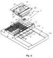
- Figure 3 is an exploded view of the laser unit and parts of the machine base, which figure more in detail shows the step copying process in the apparatus according to the invention.
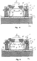
- Figure 4 is a fragmentary, vertical view through the copying machine seen along line IV-IV of figure 2 and illustrating the situation during the setting of the apparatus to the intended plate part to be copied, and figure 5 correspondingly shows the situation during the copying process.
- the basic structure of the copying machine shown in the drawings is of the known type which is manufactured by the Swedish corporation Misomex Aktiebolag and which is marketed under the name "Step And Repeat” machine and which comprises five main parts, namely a plate cassette 1, a plate loading lift 2, a laser unit 3, a discharge conveyor 4 and a movable exposure table 5.
- the plate loading lift 2, the laser unit 3 and the discharge conveyor 4 are formed as a continuous path which is serviced by the movable exposure table 5.
- the exposure table 5 is arranged to receive an un-exposed light sensitive plate 6, which is collected by the plate loading lift 2, and at the other end the exposure table 5 puts the exposed plate 6 down on the discharge conveyor 4, which feeds the plate directly into a (not shown) developing unit which is directly connected to the copying machine.
- the plate cassette 1 which is only diagrammatically indicated in the drawings, is mounted underneath the plate loading lift 2, and it is designed for receiving such a large number of plates or other light sensitive means which correspond to an entire working period, for instance 50-75 plates, so that the machine can operate fully-automatized for an entire (day) working period.
- the plates in the plate cassette preferably may be formed with punched register bores which fit register pins of the exposure table, so that any and all successively collected plates are placed in a very accurately predetermined position on the exposure table and are exposed by the laser unit over a very exatly determined area of the plate.
- register bores may be punched in the plate after the plate is placed on the exposure table. In such case the register becomes exact in relation to the exposed portions of the plate.
- the plate loading lift 2 comprises a system of tubes having suction cups 7, and it is arranged for being lowered to the plate cassette 1 by means of hydraulic or pneumatic cylinders 8 for seizing the uppermost plate 6 in the casette 1, for being lifted together with the plate and for being lowered thereby depositing the the plate on the exposure table 5.
- the machine is programmed so that the exposure table 5 is loacted in its end position far from the plate loading lift when a new plate 6 is being picked up.
- the movable exposure table 5 on which the plate 6 is laid down is movable along a straight path 8 of the machine base 10, which path can be referred to as the X-direction, between an end position far to the right in the drawings, in which position the plate 6 is laid down on the table, an intermediate position underneath the laser unit 3, in which position the plate 6 is exposed, and an end position far to the left in the drawings, in which position the plate 6 is put down on the discharge conveyor 4 for subsequent transportation to a developping machine.
- the laser unit 3 is mounted on a carriage 11 which is movable in a direction, which can be referred to as the Y-direction and which is perpendicular to the above mentioned X-direction of the exposure table 5.
- the laser carriage rolls on a path 12 which is integral with the machine base 10.
- the laser carriage 11, in turn, carries the actual laser gun 13 with its lens system movable along a path 14, which may exstend in the X-direction or the Y-direction depending on the desired sweeping direction of the laser light beam.
- the path 14 of the laser gun 13 is shown extending in the X-direction, that is parallelly to the path 12 of the laser carriage 11.
- the laser unit is arranged for exposing of only a minor portion of the light sensitive plate at the time, and the laser gun 13 therefore can be of small size and can be mounted relatively close to the exposure table 5 with the plate 6.
- FIG. 3 shows a printing plate 6 comprising thirtytwo print pages and in which plate four pages are being exposed at the time.
- the laser gun 13 is shown exploded from the laser carriage 11.
- the light beam sweeping movement of the laser gun 13 is shown with the phantom lines 15.
- the parts 16 of the plate 6 marked with the hatched lines have already been exposed whereas the non-exposed portions of the plate are shown blank.
- the laser carriage 11 adjusts itself in two alternative X-positions, one position of which is shown in figure 5, and in which the laser light beam during the exposure sweeps in an oscillating and successively in the X-direction extended movement from the far remote longitudinal edge 17 of the plate 6 and over four pictures or pages.
- the laser beam has sweep-exposed two complete and two half pages in the adjusted position.
- the laser carriage 11 moves to its second end positon in which the laser beam exposes the four additional pages 18 in this X-row of pair of pages.
- the exposure table 5 with the plate 6 moves a distance towards the discharge end corresponding to two rows of pages and the laser beam starts exposing the last series but one of four pages, etc.
- the laser unit is of a known type and is therefore not to be described in detail. It comprises a laser gun having a lens system which is adjusted so that the focus of the laser light beam falls on the light sentive plate.
- the laser may be of various types.
- a suitable laser beam source can be mentioned argon-ion-laser. Of course other types of laser beam sources can be used.
- Figures 4 and 5 show the laser unit 3 more in detail. It is obvious that the machine base 10a is directly integral with the laser base 10b, and that the path 12 of the laser base 10b provides a guide for the laser carriage, which is generally referred to with numeral 11.
- the laser carriage 11 comprises a carriage means 19 which with a grooved bar 20 is slidable on the base path 12, and which over a number of hydraulic cylinders 21 carries the laser carrier 22.
- the laser carrier 22 also has a path 23 on which a grooved bar 24 of a wagon 25 for the laser gun 13 is movable.
- the laser unit has two moving possibilities: firstly the carriage with the laser carrier 22 can be moved on the laser base 10b; and secondly the laser gun 13 as mounted on its wagon 25 can be displaced on the laser carriage 22.
- the displacements follow in the same direction, the Y-direction, but it is obvious that the laser gun 13 as well may be moved in a direction (X-direction) which is perpendicular to the direction of movement of the laser carrier 22.
- the laser carrier 22 with the wagon 25 and the laser gun 13 can be raised and lowered by means of the cylinders 21.
- the object thereof is that the laser unit can be locked to the plate 6 lying on the exposure table 5.
- the laser carrier 22 is formed with a downwards extending, box-formed foot 26 which at the bottom thereof may have a sealing antiskid element 27 adapted to get into contact with the plate 6.
- Figure 4 shows the laser unit 3 in its raised position in which position the exposure table 5 and/or the laser carriage 11 can be moved to a new adjustment position, or a ready exposed plate 6 can be expelled to the discharge conveyor.
- Figure 5 shows the same apparatus in its fully lowered position in which position the plate 6 is being exposed.
- the entire apparatus plant comprising the plate cassette 1, the plate loading lift 2, the laser unit 3 and the discharge conveyor 4 are formed light sealed, so that the plant can be used also in soft daylight.
- the discharge conveyor thereby is connected to a developing station which can be placed in any type of dark-room. It is indicated in figures 1 and 2 that the laser gun 13, during its movement in relation to the laser carrier 22, is light sealed by means of a Venetian blind 28 or a similar light sealing means.
- the described apparatus functions as follows: In the starting position the exposure table 5 is retracted from the plate loading lift 2, and said lift thereby can be lowered to collect and lift the uppermost light sensitive plate 6 of the plate cassette 1.
- the laser unit 3 is in its raised position shown in figure 4.
- the exposure table 5 now is moved to a position under the plate 6 hanging in the plate lift 2, whereupon the plate 6 is lowered and is secured, by means its punch holes, on equivalent locating pins of the exposure table.
- the plate loading lift 2 is lifted, and the exposure table 5 with the plate 6 secured thereon is moved such a long distance in the X-direction under the laser unit 3 which corresponds to the number of Y-direction (longitudinal) rows of pages to be exposed.
- the laser unit 3 Concurrently therewith the laser unit 3 is moved in the Y-direction to a position for exposing the number of X-direction (cross) rows of pages which are to be exposed, e.g. two or four pages out of an 8-, 16- or 32-pages light sensitive plate.
- the laser unit 3 now is lowered by the actuation of the hydraulic cylnders 21 so that the bottom of the foot 26 of the laser carrier 22 engages the upper surface of the plate 6.
- the laser unit 3 is raised from the plate 6 and the laser carriage 11 moves a predetermined distance in the Y-direction to enter a position for exposing the next series of, for instance, four pages.
- the exposure table 5 moves a distance corresponding to two pages in the X-direction, whereafter the next sequence of exposure of 4 + 4 pages is started.
- the plate loading lift 2 collects a new, un-exposed plate 6 from the plate cassette 5 and a new cycle is started.
Landscapes
- Physics & Mathematics (AREA)
- Optics & Photonics (AREA)
- General Physics & Mathematics (AREA)
- Exposure And Positioning Against Photoresist Photosensitive Materials (AREA)
- Manufacture Or Reproduction Of Printing Formes (AREA)
Abstract
Description
- The present invention relates to a method and an apparatus for exposing multi-pages original images onto a light sensitive offset plate or an intaglio plate by means of a laser exposure/burning process.
- Lately some print makers have started to use laser light beams for exposing light sensitive offset plates or intaglio plates. The advantages of using laser is, among other things, that it is possible:
- to execute the exposure directly from computer stored information concerning text, sketches and half-tone pictures etc. without the need of using negative of positive transparent films, as has so far been usual,
- that the size of the dots which are to create the image can, within wide limits, be determined and controlled, in particular the dot creating a half-tone picture in the print and which corresponds to the screen dot in conventional screen copying processes, and this is possible in that the laser light builds up the screen dot from a large number of pixles, generally between 64 and 256 pixles per screen dot,
- and that therefore the gradation of the grey scale of the laser reproduced image on the printing plate can be varied within wide limits.
- Like in conventional copying processes the laser light provides an activation of the illuminated part of the printing plate so that, in the succeeding developing process, said activated printing plate parts become ink carrying if the printing plate is of the positive type, or non-ink carrying respectively if the printing plate is of the negative type.
- There are to-day three main methods of laser exposing printing plates, namely exposing a plate lying on a flat bed, the so called flat bed method, exposing a plate mounted inside a cylindrical drum whereby the exposing is made from inside the curved plate, which process is called internal drum method, and exposing of a plate mounted exteriorly on a cylindrical drum, whereby the exposure is made from outside, which process is called external drum method.
- Each one of said three methods is disadvantageous in some respects;
- In the flat bed method the entire printing plate is exposed in one single exposure step by means of a sweeping laser light beam. Generally the laser apparatus including the so called "laser gun" is starionary, whereas the printing plate is displacable on an exposure table in relation to the laser unit. During the exposure the laser unit emits an oscillating light beam which hits the plate while said plate is slowly moving passed the laser unit until the entire plate has been exposed. Alternatively it is possible to keep the exposure table still standing and to allow the laser unit to wander over the plate during the exposure. In this type of the flat bed copying machine the distance from the laser gun or the lens system thereof to the side edges of the printing plate is substantially longer than to the central parts of the plate, and this has as an effect that the sharpness and the shape of the laser dot exposed on the printing plate varies depending on where the laser beam hits the plate. For reducing, to some extent, the problem with this variation in dot sharpness and shape the laser gun generally is mounted on a relative high distance above the printing plate, and for equalizing the always existing unavoidable variations in dot sharpness and shape in this type of copying machine the laser gun generally is adjusted so that the sharpness of the laser dot is located slightly to high at the edges of the plate and slightly to low at the central parts of the plate. As a consequence an ideal dot is located somewhere between the centre and the edges of the plate. Depending on the said machine design the laser copying machine is high and clumsy, and the laser burning is relatively uneven when comparing different parts of the printing plate. Another problem is to, as far as possible, eliminate the vibrations which unevitably appear when the copying table and the laser unit move in relation to each other;
- Depending on the large height of the apparatus it is very sensitive to vibrations, and even a very little unexpected movement of the laser dot on the printing plate, for instance caused by a slight shaking of the laser gun, the dot will be unsharp on the printing plate, in particular since the laser gun normally projects between 64 and 256 pixles for creating each separate screen dot when exposing an optimum grey scale;
- For a good result in this method it is necessary that the base for the printing plate, generally the base of the copying machine, is extremely even, since even a very little un-eveness in the surface makes the sharpness of the dots vary;
- It may also be very difficult to move the printing plate and the laser gun with an exact speed and a uniform movement in relation to each other, and it often happens that there is a slight difference in speed and uniformity and this makes the laser dots slightly overlap each other or to be loacted too far from each other, and this, in turn, makes stripes appear in the ready print;
- The necessary large working area for the laser gun makes it necessary to use a heavy laser gun and a large and expensive lens system, and therefore the apparatus will be remarkably expensive;
- In the internal and external drum methods the printing plate is generally more safely secured in relation to the laser gun than in the flat bed method, and therefore a better copying quality is obtained than with the flat bed machines. In the internal and external drum methods, however, there are on the contrary problems in mounting of the printing plate inside and on the outer surface of the drum respectively; in some cases there also are problems in obtaining an even laser exposure all over the width of the plate, especially in the internal drum method; there are also problems in obtaining an exact fixedly mounting of the printing plate on the drum (for accurate plate register); and usually there is a restricted maximum size for the printing plate.
- A serious problem in all known copying methods is that the printing plate and the laser unit may move in relation to each other during the copying process. Therefore a special purpose of the invention is to foresee that the laser unit and the printing plate are safely secured in relation to each other before the copying process is started, thereby eliminating any possibility of said parts to move in relation to each other.
- The object of the invention further is to suggest a method and an apparatus which solves most of the above mentioned problems and disadvantages in the priorly known methods and apparatus; and to suggest a method and an apparatus which further allows a substantially fully automatized exposure of several successive printing plates of the same or varying size; in which the apparatus is substantially lower and claims for less precision and accuracy in the manufacture than the apparatus for executing the priorly known methods; in which the laser gun is mounted substantially closer to the printing plate to be exposed than in priorly known apparatus; in which the apparatus is substantially less sensitive to shakings and vibrations; and in which the apparatus is slimplier and cheaper than all the above mentioned three priorly known laser copying machine types.
- According to the invention said objects are fulfilled in that the laser unit is lowered and is safely locked to the plate laying on the exposure table before the exposing isstarted, whereupon the printing plate is exposed in several stages by means of laser light beams, and whereby the plate accordingly is exposed in several successive stages with only a minor part of the plate at the time, for instance with two or four pages at the time of the usually 16, 32 or 64 pages large printing plate This is made by an automatized handling comprising collecting an un-exposed light sensitive plate, exposing said plate by the action of four different but cooperating movements, namely a) a stepwise displacement of a plate table in a certain direction, the X-direction, b) a stepwise displacement of the laser unit in a Y-direction and c) a lowering and locking of the laser unit against the printing plate, and d) a successive movement of a special part (the laser gun) of the laser unit in the X-direction or the Y-direction during the oscillatory sweep exposure, which movement alternatively can be made in the X-direction or the Y-direction, and finally an expelling of the exposed printing plate from the copying apparatus for subsequent developing and other handling.
- The method also makes it possible to make use of two or more small laser units parallelly to each other.
- It should be emphasized that the designation "light sensitive plate" or "printing plate" is meant to include not only offset and intaglio printing plates but also any other possible types of light sensitive material like light sensitive films (negative and positive).
- Further characteristics of, and advantages with, the invention will be evident from the following detailed specification in which reference will be made to the accompanying drawings, which illustrate an embodiment of an apparatus according to the invention.
- In the drawings figure 1 diagrammatically shows a copying plant according to the invention having, for the sake of clearness the protection housings for the plate magazine and the plate expeller partly opened. Figure 2 is an X-ray sketch of the same plant as in figure 1 showing more in detail the plate feeder and the plate expeller. Figure 3 is an exploded view of the laser unit and parts of the machine base, which figure more in detail shows the step copying process in the apparatus according to the invention. Figure 4 is a fragmentary, vertical view through the copying machine seen along line IV-IV of figure 2 and illustrating the situation during the setting of the apparatus to the intended plate part to be copied, and figure 5 correspondingly shows the situation during the copying process.
- The basic structure of the copying machine shown in the drawings is of the known type which is manufactured by the Swedish corporation Misomex Aktiebolag and which is marketed under the name "Step And Repeat" machine and which comprises five main parts, namely a plate cassette 1, a
plate loading lift 2, alaser unit 3, a discharge conveyor 4 and a movable exposure table 5. - The
plate loading lift 2, thelaser unit 3 and the discharge conveyor 4 are formed as a continuous path which is serviced by the movable exposure table 5. At one end the exposure table 5 is arranged to receive an un-exposed lightsensitive plate 6, which is collected by theplate loading lift 2, and at the other end the exposure table 5 puts the exposedplate 6 down on the discharge conveyor 4, which feeds the plate directly into a (not shown) developing unit which is directly connected to the copying machine. - The plate cassette 1, which is only diagrammatically indicated in the drawings, is mounted underneath the
plate loading lift 2, and it is designed for receiving such a large number of plates or other light sensitive means which correspond to an entire working period, for instance 50-75 plates, so that the machine can operate fully-automatized for an entire (day) working period. As usual the plates in the plate cassette preferably may be formed with punched register bores which fit register pins of the exposure table, so that any and all successively collected plates are placed in a very accurately predetermined position on the exposure table and are exposed by the laser unit over a very exatly determined area of the plate. - Alternatively register bores may be punched in the plate after the plate is placed on the exposure table. In such case the register becomes exact in relation to the exposed portions of the plate.
- The
plate loading lift 2 comprises a system of tubes havingsuction cups 7, and it is arranged for being lowered to the plate cassette 1 by means of hydraulic orpneumatic cylinders 8 for seizing theuppermost plate 6 in the casette 1, for being lifted together with the plate and for being lowered thereby depositing the the plate on the exposure table 5. The machine is programmed so that the exposure table 5 is loacted in its end position far from the plate loading lift when anew plate 6 is being picked up. - The movable exposure table 5 on which the
plate 6 is laid down is movable along astraight path 8 of themachine base 10, which path can be referred to as the X-direction, between an end position far to the right in the drawings, in which position theplate 6 is laid down on the table, an intermediate position underneath thelaser unit 3, in which position theplate 6 is exposed, and an end position far to the left in the drawings, in which position theplate 6 is put down on the discharge conveyor 4 for subsequent transportation to a developping machine. - The
laser unit 3 is mounted on acarriage 11 which is movable in a direction, which can be referred to as the Y-direction and which is perpendicular to the above mentioned X-direction of the exposure table 5. The laser carriage rolls on apath 12 which is integral with themachine base 10. Thelaser carriage 11, in turn, carries theactual laser gun 13 with its lens system movable along apath 14, which may exstend in the X-direction or the Y-direction depending on the desired sweeping direction of the laser light beam. In figures 3-5 thepath 14 of thelaser gun 13 is shown extending in the X-direction, that is parallelly to thepath 12 of thelaser carriage 11. - The laser unit is arranged for exposing of only a minor portion of the light sensitive plate at the time, and the
laser gun 13 therefore can be of small size and can be mounted relatively close to the exposure table 5 with theplate 6. As mentioned above this involves several advantages, of which it should be emphasized that there is a very little risque of shaking-unsharpness on theplate 6 on the exposure table 5, that thelaser gun 13 and the lens system thereof can be made of relatively small size and can be manufactured to low costs, that a good precision and accuracy is obtained for the laser dots on the light sensitive plate, and that there is a relatively little difference in focal distances at different parts of each exposure portion of theplate 6. - As one typical example figure 3 shows a
printing plate 6 comprising thirtytwo print pages and in which plate four pages are being exposed at the time. For the sake of clearness thelaser gun 13 is shown exploded from thelaser carriage 11. The light beam sweeping movement of thelaser gun 13 is shown with the phantom lines 15. Theparts 16 of theplate 6 marked with the hatched lines have already been exposed whereas the non-exposed portions of the plate are shown blank. Upon exposure of four pages at the time, as in the illustrated case, thelaser carriage 11 adjusts itself in two alternative X-positions, one position of which is shown in figure 5, and in which the laser light beam during the exposure sweeps in an oscillating and successively in the X-direction extended movement from the far remotelongitudinal edge 17 of theplate 6 and over four pictures or pages. In the illustrated position the laser beam has sweep-exposed two complete and two half pages in the adjusted position. - When the four actual pages have been exposed the
laser carriage 11 moves to its second end positon in which the laser beam exposes the fouradditional pages 18 in this X-row of pair of pages. When also said fourpages 18 have been exposed the exposure table 5 with theplate 6 moves a distance towards the discharge end corresponding to two rows of pages and the laser beam starts exposing the last series but one of four pages, etc. - The laser unit is of a known type and is therefore not to be described in detail. It comprises a laser gun having a lens system which is adjusted so that the focus of the laser light beam falls on the light sentive plate. The laser may be of various types. As an example of a suitable laser beam source can be mentioned argon-ion-laser. Of course other types of laser beam sources can be used.
- Figures 4 and 5 show the
laser unit 3 more in detail. It is obvious that themachine base 10a is directly integral with thelaser base 10b, and that thepath 12 of thelaser base 10b provides a guide for the laser carriage, which is generally referred to withnumeral 11. Thelaser carriage 11 comprises a carriage means 19 which with agrooved bar 20 is slidable on thebase path 12, and which over a number ofhydraulic cylinders 21 carries thelaser carrier 22. Thelaser carrier 22 also has a path 23 on which agrooved bar 24 of awagon 25 for thelaser gun 13 is movable. - The laser unit has two moving possibilities: firstly the carriage with the
laser carrier 22 can be moved on thelaser base 10b; and secondly thelaser gun 13 as mounted on itswagon 25 can be displaced on thelaser carriage 22. In the illustrated case the displacements follow in the same direction, the Y-direction, but it is obvious that thelaser gun 13 as well may be moved in a direction (X-direction) which is perpendicular to the direction of movement of thelaser carrier 22. - It is important to the invention that the
laser carrier 22 with thewagon 25 and thelaser gun 13 can be raised and lowered by means of thecylinders 21. The object thereof is that the laser unit can be locked to theplate 6 lying on the exposure table 5. To this end thelaser carrier 22 is formed with a downwards extending, box-formedfoot 26 which at the bottom thereof may have a sealingantiskid element 27 adapted to get into contact with theplate 6. - This embodiment is good for two reasons:
- a) by lowering the
carrier foot 26 with its sealingelement 27 into contact with theplate 6 it is not possible for thelaser unit 3 to move in relation to theplate 6, and the laser light will fall with good sharpness and precision on each separate point of the plate; - b) depending on the box-shape of the
foot 26 of thelaser carrier 22 said foot effectively restricts exactly the area of theplate 6 which is to be exposed, and the exposing consequently is made only within this specific area. - Figure 4 shows the
laser unit 3 in its raised position in which position the exposure table 5 and/or thelaser carriage 11 can be moved to a new adjustment position, or a ready exposedplate 6 can be expelled to the discharge conveyor. Figure 5 shows the same apparatus in its fully lowered position in which position theplate 6 is being exposed. - The entire apparatus plant comprising the plate cassette 1, the
plate loading lift 2, thelaser unit 3 and the discharge conveyor 4 are formed light sealed, so that the plant can be used also in soft daylight. The discharge conveyor thereby is connected to a developing station which can be placed in any type of dark-room. It is indicated in figures 1 and 2 that thelaser gun 13, during its movement in relation to thelaser carrier 22, is light sealed by means of a Venetian blind 28 or a similar light sealing means. - The described apparatus functions as follows:
In the starting position the exposure table 5 is retracted from theplate loading lift 2, and said lift thereby can be lowered to collect and lift the uppermost lightsensitive plate 6 of the plate cassette 1. Thelaser unit 3 is in its raised position shown in figure 4. The exposure table 5 now is moved to a position under theplate 6 hanging in theplate lift 2, whereupon theplate 6 is lowered and is secured, by means its punch holes, on equivalent locating pins of the exposure table. Theplate loading lift 2 is lifted, and the exposure table 5 with theplate 6 secured thereon is moved such a long distance in the X-direction under thelaser unit 3 which corresponds to the number of Y-direction (longitudinal) rows of pages to be exposed. Concurrently therewith thelaser unit 3 is moved in the Y-direction to a position for exposing the number of X-direction (cross) rows of pages which are to be exposed, e.g. two or four pages out of an 8-, 16- or 32-pages light sensitive plate. - The
laser unit 3 now is lowered by the actuation of thehydraulic cylnders 21 so that the bottom of thefoot 26 of thelaser carrier 22 engages the upper surface of theplate 6. - In the position now taken the actual number of pages are exposed in that the
laser gun 13, in a lightbeam sweeping movement 15, moves in the Y-direction (alternatively in the X-direction) over the four pages on itspath 14 of movement. - After the said four pages have been exposed the
laser unit 3 is raised from theplate 6 and thelaser carriage 11 moves a predetermined distance in the Y-direction to enter a position for exposing the next series of, for instance, four pages. - When now a row consisting of eight pages has been exposed the exposure table 5 moves a distance corresponding to two pages in the X-direction, whereafter the next sequence of exposure of 4 + 4 pages is started. Correspondingly the exposure table 5 and the
laser unit 3 step forward until the full series of 8 exposures (8 * 4 = 32 pages) is completed, whereupon the exposure table 5 is moved to a position above the discharge conveyor 4, which receives theplate 6, as known per se, and forwards same to a means for development or any other supplementary handling. At the same time as the ready exposed plate is deposited on the discharge conveyor 4 theplate loading lift 2 collects a new,un-exposed plate 6 from theplate cassette 5 and a new cycle is started. -
- 1
- plate cassette
- 2
- plate loading lift
- 3
- laser unit
- 4
- discharge conveyor
- 5
- exposure table
- 6
- plate
- 7
- lift unit with suction cups
- 8
- cylinder
- 9
- path (for 5)
- 10
- machine base
- 11
- carriage (for 3)
- 12
- path (for 11)
- 13
- laser gun
- 14
- path (for 13)
- 15
- beams (13)
- 16
- exposed part
- 17
- edge (of 6)
- 18
- additional pages
- 19
- carriage means
- 20
- bar
- 21
- cylinder
- 22
- laser carrier
- 23
- path
- 24
- bar
- 25
- wagon (for 13)
- 26
- carrier foot
- 27
- sealing element
- 28
- Venetian blid
Claims (10)
- Method of exposing multi-pages original images or several separate text and/or picture portions onto a light sensitive material like an offset plate or an intaglio plate by means of light exposure, wherein a light sensitive plate (6) is placed on a stepwise movable exposure table (5), the exposure table (5) with the plate (6) is moved to a predetermined position under a laser unit (3), the laser unit (3) is lowered to locking engagement with plate (6) on the exposure table (5), the plate is exposed by means of laser light beams, the laser unit (3) is raised from the plate (6), and the plate (6) is discharged for development and any other further handling.
- Method according to claim 1, characterized in that the entire exposure operation is made fully automatized by collecting a light sensitive plate (6) from a plate cassette (1), putting said plate (6) on the stepwise movable exposure table (5), introducing the exposure table (5) with the plate (6) under the laser unit (3), lowering of the laser unit (3) into locking engagement with the plate (6), exposing the plate in several successive stages, and discharging the exposed plate (6) for subsequent developing etc. at the same time as a new, unexposed plate (6) is collected from the plate cassette (1).
- Method according to claim 2, characterized in that the light sensitive plate (6) is exposed in several stages with a minor portion of the light sensitive plate at the time, for instance with two or four pages at the time out of a plate comprising 16, 32 or 64 pages, whereby the exposure is made by executing four cooperating movements of the parts of an exposure plant, namely a) a stepwise displacement of the exposure table (5) in a first direction (X-direction), b) a stepwise displacement of the laser unit (3) in a second direction (Y-direction) which is perpendicular to said first direction, c) a lowering of the laser unit (3) into locking engagement with the light sensitive plate (6), and d) a successive displacement in the Y-direction or in the X-direction of a laser gun (13) whereby said laser gun (13) is sweep exposing the light sensitive plate while the exposure table (5) and the laser unit (3) are in fixed positions, whereupon the laser unit (3) is raised, and the laser unit (3) and/or the exposure table (5) are/is moved to a new position for exposing of a new part of the plate (6).
- Apparatus for executing the method according to any of claims 1-3 for exposing of multi-pages original images or several separate text and/or picuture portions on a light sensitive material like an offset plate or an intaglio plate (6) by light exposure by means of a copying machine comprising a cassette (1) for a light sensitive material, e.g. light sensitive films or plates (6), a laser unit (3) for light exposing said light sensitive material (6), a discharge conveyor (4) for the ready exposed light sensitive material, and an exposure table (5) having means for holding the light sensitive material (6) in a predeterined position thereon and arranged movable between the plate cassette (1) and the discharge conveyor (4) and under the laser unit (3), characterized in that the laser unit (3) is formed capable of taking two different positions, namely a raised position, in which the exposure table (5) with the plate (6) can be moved freely under the laser unit (3), and a lowered position, in which the laser unit (3) is being pressed into locking engagement with the plate (6) on the exposure table (5) for making a displacement impossible of the plate (6) and the laser unit (3) in relation to each other.
- Apparatus according to claim 4, characterized in that the laser unit (3) is displacably mounted on a laser base (10b) which is fixedly connected to the base (10a) of the entire copying machine, and in that the laser unit (3) comprises a laser carrier (11) which can be raised and lowered and which is movable on the laser base (10b), and a laser gun wagon (25), which is, in turn, displacable on the up and down movable laser carrier (11), so that the laser gun wagen (25), at still standing laser carrier (11), can be moved continuously while sweep exposing a light sensitive plate (6).
- Apparatus according to claim 5, characterized in that the laser gun wagon (25) can be moved on the laser carrier (11) in the same direction as said laser carrier (11) can be moved on the laser base (10b), or perpendicularly therto, or in any direction differing from the moving direction of the laser carrier (11).
- Apparatus according to any of claims 4, 5 or 6, characterized in that the laser carrier (11) is made of two parts, namely a lower laser carrier carriage means (19) which is movable on a path of the laser base (10b) and an upper laser carrier part (22) which is secured against any horizontal displacement in relation to the laser carriage means (19) but which can be raised and lowered in relation to said laser carriage means (19) by means of raising and lowering means (21).
- Apparatus according to claim 7, characterized in that the upper laser carrier part (22) is formed as a light sealed box having a foot (26) which projects downwards between the laser bases (10b) and which can be brought into sealing and locking engagement with a light sensitive plate (6) presented on the exposure table (5).
- Apparatus according to claim 8, characterized in that the laser gun (13) is light-sealingly connected to the upper surface of the laser carrier, so that the laser light beams sweep through the light sealed foot, and in that the laser gun (13) is displacable in relation to the laser carrier (22) under light sealed condition provided by Venetian blinds (28) or similar light sealing menas.
- Apparatus according to any of claims 4-7, characterized in that the apparatus comprises a plate cassette (1) containing a large number of plates (6) and a plate loading lift (2) arranged for collecting a plate (6) when the exposure table (5) is in its depositing position at the discharge conveyor (4), and in that the various movable parts of the apparatus are super-guided by a computer which is programmed so that the displacement of the exposure table (5), the stepwise exposing of the plate (6) and the discharging of the exposed plate is made fully automatized in an successively proceeding stage, and whereby the collecting of a light sensitive plate (6) is made concurrently with the depositing of a ready exposed plate on the discharge conveyor (4).
Applications Claiming Priority (3)
| Application Number | Priority Date | Filing Date | Title |
|---|---|---|---|
| SE9101619 | 1991-05-28 | ||
| SE9101619A SE502087C2 (en) | 1991-05-28 | 1991-05-28 | Method and apparatus for laser copying with height-adjustable laser unit |
| PCT/SE1992/000356 WO1992021518A1 (en) | 1991-05-28 | 1992-05-26 | Method and apparatus of exposing light sensitive material by means of a copying machine having a vertically movable laser unit |
Publications (2)
| Publication Number | Publication Date |
|---|---|
| EP0586497A1 EP0586497A1 (en) | 1994-03-16 |
| EP0586497B1 true EP0586497B1 (en) | 1995-12-20 |
Family
ID=20382865
Family Applications (1)
| Application Number | Title | Priority Date | Filing Date |
|---|---|---|---|
| EP92911517A Expired - Lifetime EP0586497B1 (en) | 1991-05-28 | 1992-05-26 | Method and apparatus of exposing light sensitive material by means of a copying machine having a vertically movable laser unit |
Country Status (6)
| Country | Link |
|---|---|
| US (1) | US5550574A (en) |
| EP (1) | EP0586497B1 (en) |
| AU (1) | AU1923292A (en) |
| DE (1) | DE69206983T2 (en) |
| SE (1) | SE502087C2 (en) |
| WO (1) | WO1992021518A1 (en) |
Families Citing this family (10)
| Publication number | Priority date | Publication date | Assignee | Title |
|---|---|---|---|---|
| JP2905746B2 (en) | 1996-11-06 | 1999-06-14 | 株式会社金田機械製作所 | Printing plate exposure equipment |
| US5934195A (en) * | 1997-06-05 | 1999-08-10 | Western Litho Plate & Supply Co. | Apparatus for and method of exposing lithographic plates |
| US6899030B2 (en) * | 2003-05-05 | 2005-05-31 | Eastman Kodak Company | Lithographic plate imaging system to minimize plate misregistration for multicolor printing applications |
| US8236479B2 (en) | 2008-01-23 | 2012-08-07 | E I Du Pont De Nemours And Company | Method for printing a pattern on a substrate |
| EP2085820B1 (en) * | 2008-01-30 | 2015-02-25 | E. I. du Pont de Nemours and Company | Apparatus and method for preparing relief printing form |
| US8241835B2 (en) | 2008-01-30 | 2012-08-14 | E I Du Pont De Nemours And Company | Device and method for preparing relief printing form |
| WO2011002967A1 (en) | 2009-07-02 | 2011-01-06 | E. I. Du Pont De Nemours And Company | Method for printing a material onto a substrate |
| US9069252B2 (en) | 2011-08-26 | 2015-06-30 | E I Du Pont De Nemours And Company | Method for preparing a relief printing form |
| US9387691B2 (en) * | 2011-12-20 | 2016-07-12 | First Solar, Inc. | Method and apparatus for laser marking an object |
| US9097974B2 (en) | 2012-08-23 | 2015-08-04 | E I Du Pont De Nemours And Company | Method for preparing a relief printing form |
Family Cites Families (9)
| Publication number | Priority date | Publication date | Assignee | Title |
|---|---|---|---|---|
| DE162469C (en) * | ||||
| US4052603A (en) * | 1974-12-23 | 1977-10-04 | International Business Machines Corporation | Object positioning process and apparatus |
| SE389057B (en) * | 1975-04-30 | 1976-10-25 | Misomex Ab | PROCEDURE FOR PREPARATION OF TRANSLATION ORIGINAL FOR PRESSURE PLACE MANUFACTURE, OR FOR DIRECT PREPARATION OF A PRESSURE PLATE |
| DE2725308A1 (en) * | 1976-06-10 | 1977-12-22 | Hoechst Co American | Laser imaging system producing aluminium offset plates - uses visible coherent light on emulsion contg. negative diazo prods. |
| FR2363541A1 (en) * | 1976-09-01 | 1978-03-31 | Ugine Kuhlmann | ACYLOXY-N, N 'DIACYLMALONAMIDES AND THEIR METHOD OF PREPARATION |
| FR2474708B1 (en) * | 1980-01-24 | 1987-02-20 | Dme | HIGH-RESOLUTION MICROPHOTOLITHOGRAPHY PROCESS |
| US4993696A (en) * | 1986-12-01 | 1991-02-19 | Canon Kabushiki Kaisha | Movable stage mechanism |
| DE3937557C2 (en) * | 1989-11-10 | 1994-05-26 | Krause Biagosch Gmbh | Device for the production of printing plates |
| US5322268A (en) * | 1991-11-12 | 1994-06-21 | Fuji Photo Film Co., Ltd. | Method of and apparatus for supplying photosensitive lithographic printing plates |
-
1991
- 1991-05-28 SE SE9101619A patent/SE502087C2/en not_active IP Right Cessation
-
1992
- 1992-05-26 US US08/137,194 patent/US5550574A/en not_active Expired - Fee Related
- 1992-05-26 WO PCT/SE1992/000356 patent/WO1992021518A1/en not_active Ceased
- 1992-05-26 DE DE69206983T patent/DE69206983T2/en not_active Expired - Fee Related
- 1992-05-26 EP EP92911517A patent/EP0586497B1/en not_active Expired - Lifetime
- 1992-05-26 AU AU19232/92A patent/AU1923292A/en not_active Abandoned
Also Published As
| Publication number | Publication date |
|---|---|
| SE9101619L (en) | 1992-11-29 |
| US5550574A (en) | 1996-08-27 |
| AU1923292A (en) | 1993-01-08 |
| WO1992021518A1 (en) | 1992-12-10 |
| SE9101619D0 (en) | 1991-05-28 |
| DE69206983T2 (en) | 1996-05-23 |
| DE69206983D1 (en) | 1996-02-01 |
| SE502087C2 (en) | 1995-08-07 |
| EP0586497A1 (en) | 1994-03-16 |
Similar Documents
| Publication | Publication Date | Title |
|---|---|---|
| US5550574A (en) | Method and apparatus for exposing light sensitive material by means of a copying machine having a vertically movable laser unit | |
| DE69023186T2 (en) | Exposure device. | |
| US5815243A (en) | Electronic prepress apparatus for producing lithographic printing plates | |
| DE3687372T2 (en) | SCAN ARRANGEMENT. | |
| EP0746800B1 (en) | Process and device for the photomechanical production of structured surfaces, in particular for exposing offset plates | |
| EP0586500B1 (en) | Method and apparatus for automatized exposing of light sensitive material by means of laser light | |
| DE3328247A1 (en) | METHOD FOR FORMING ALIGNMENT TOKENS | |
| EP0523673B1 (en) | Photosensitive material printing apparatus | |
| US4640612A (en) | Method and apparatus for controlling continuously operation of automatic photo-composer | |
| US6040896A (en) | Method of printing photosensitive material | |
| DE69220106T2 (en) | Printing device for photosensitive material and adjusting device | |
| WO1991013511A1 (en) | Process and device for producing a reproducible | |
| EP0441254B1 (en) | Photocomposing method and system therefor | |
| US4860060A (en) | Microfiche printing system and method | |
| US4094605A (en) | Apparatus for producing identical sheets of material having a number of representations thereon | |
| EP0552823B1 (en) | Process camera | |
| JP4712517B2 (en) | Template data creation method and apparatus, template matching method and apparatus, and drawing method and apparatus | |
| JPH1067087A (en) | Registration mark formation method, printing plate and registration mark drawing apparatus | |
| DE3047205A1 (en) | PROCESSING STATION FOR CHARGING, EXPOSURE AND DEVELOPING PRINTING FORMS | |
| JP3208146B2 (en) | Automatic breeding machine | |
| DE69103697T2 (en) | Device for measuring the size of the positional deviation of a recording sheet. | |
| GB2162015A (en) | Method of screen printing | |
| JP3371834B2 (en) | PRINTING APPARATUS AND PROGRAM RECORDING MEDIUM THEREOF | |
| JPH0750749Y2 (en) | Printing machine | |
| EP0404522A3 (en) | Multilayer imaging article for transfer color proofing |
Legal Events
| Date | Code | Title | Description |
|---|---|---|---|
| PUAI | Public reference made under article 153(3) epc to a published international application that has entered the european phase |
Free format text: ORIGINAL CODE: 0009012 |
|
| 17P | Request for examination filed |
Effective date: 19931026 |
|
| AK | Designated contracting states |
Kind code of ref document: A1 Designated state(s): DE GB |
|
| RIN1 | Information on inventor provided before grant (corrected) |
Inventor name: DILLOW, BRIAN ST. PIERRE MISOMEX AKTIEBOLAG |
|
| 17Q | First examination report despatched |
Effective date: 19950413 |
|
| GRAA | (expected) grant |
Free format text: ORIGINAL CODE: 0009210 |
|
| AK | Designated contracting states |
Kind code of ref document: B1 Designated state(s): DE GB |
|
| REF | Corresponds to: |
Ref document number: 69206983 Country of ref document: DE Date of ref document: 19960201 |
|
| PLBE | No opposition filed within time limit |
Free format text: ORIGINAL CODE: 0009261 |
|
| STAA | Information on the status of an ep patent application or granted ep patent |
Free format text: STATUS: NO OPPOSITION FILED WITHIN TIME LIMIT |
|
| 26N | No opposition filed | ||
| PGFP | Annual fee paid to national office [announced via postgrant information from national office to epo] |
Ref country code: GB Payment date: 19991124 Year of fee payment: 8 |
|
| PGFP | Annual fee paid to national office [announced via postgrant information from national office to epo] |
Ref country code: DE Payment date: 19991222 Year of fee payment: 8 |
|
| PG25 | Lapsed in a contracting state [announced via postgrant information from national office to epo] |
Ref country code: GB Free format text: LAPSE BECAUSE OF NON-PAYMENT OF DUE FEES Effective date: 20000526 |
|
| GBPC | Gb: european patent ceased through non-payment of renewal fee |
Effective date: 20000526 |
|
| PG25 | Lapsed in a contracting state [announced via postgrant information from national office to epo] |
Ref country code: DE Free format text: LAPSE BECAUSE OF NON-PAYMENT OF DUE FEES Effective date: 20010301 |