EP0586461B1 - Gasketed membrane electrode assembly for electrochemical fuel cells - Google Patents
Gasketed membrane electrode assembly for electrochemical fuel cells Download PDFInfo
- Publication number
- EP0586461B1 EP0586461B1 EP92910726A EP92910726A EP0586461B1 EP 0586461 B1 EP0586461 B1 EP 0586461B1 EP 92910726 A EP92910726 A EP 92910726A EP 92910726 A EP92910726 A EP 92910726A EP 0586461 B1 EP0586461 B1 EP 0586461B1
- Authority
- EP
- European Patent Office
- Prior art keywords
- membrane
- cathode
- anode
- periphery
- electrode assembly
- Prior art date
- Legal status (The legal status is an assumption and is not a legal conclusion. Google has not performed a legal analysis and makes no representation as to the accuracy of the status listed.)
- Expired - Lifetime
Links
Images


Classifications
-
- C—CHEMISTRY; METALLURGY
- C25—ELECTROLYTIC OR ELECTROPHORETIC PROCESSES; APPARATUS THEREFOR
- C25B—ELECTROLYTIC OR ELECTROPHORETIC PROCESSES FOR THE PRODUCTION OF COMPOUNDS OR NON-METALS; APPARATUS THEREFOR
- C25B9/00—Cells or assemblies of cells; Constructional parts of cells; Assemblies of constructional parts, e.g. electrode-diaphragm assemblies; Process-related cell features
-
- H—ELECTRICITY
- H01—ELECTRIC ELEMENTS
- H01M—PROCESSES OR MEANS, e.g. BATTERIES, FOR THE DIRECT CONVERSION OF CHEMICAL ENERGY INTO ELECTRICAL ENERGY
- H01M8/00—Fuel cells; Manufacture thereof
- H01M8/02—Details
- H01M8/0271—Sealing or supporting means around electrodes, matrices or membranes
- H01M8/0273—Sealing or supporting means around electrodes, matrices or membranes with sealing or supporting means in the form of a frame
-
- H—ELECTRICITY
- H01—ELECTRIC ELEMENTS
- H01M—PROCESSES OR MEANS, e.g. BATTERIES, FOR THE DIRECT CONVERSION OF CHEMICAL ENERGY INTO ELECTRICAL ENERGY
- H01M8/00—Fuel cells; Manufacture thereof
- H01M8/10—Fuel cells with solid electrolytes
- H01M8/1007—Fuel cells with solid electrolytes with both reactants being gaseous or vaporised
-
- H—ELECTRICITY
- H01—ELECTRIC ELEMENTS
- H01M—PROCESSES OR MEANS, e.g. BATTERIES, FOR THE DIRECT CONVERSION OF CHEMICAL ENERGY INTO ELECTRICAL ENERGY
- H01M2300/00—Electrolytes
- H01M2300/0017—Non-aqueous electrolytes
- H01M2300/0065—Solid electrolytes
- H01M2300/0082—Organic polymers
-
- Y—GENERAL TAGGING OF NEW TECHNOLOGICAL DEVELOPMENTS; GENERAL TAGGING OF CROSS-SECTIONAL TECHNOLOGIES SPANNING OVER SEVERAL SECTIONS OF THE IPC; TECHNICAL SUBJECTS COVERED BY FORMER USPC CROSS-REFERENCE ART COLLECTIONS [XRACs] AND DIGESTS
- Y02—TECHNOLOGIES OR APPLICATIONS FOR MITIGATION OR ADAPTATION AGAINST CLIMATE CHANGE
- Y02E—REDUCTION OF GREENHOUSE GAS [GHG] EMISSIONS, RELATED TO ENERGY GENERATION, TRANSMISSION OR DISTRIBUTION
- Y02E60/00—Enabling technologies; Technologies with a potential or indirect contribution to GHG emissions mitigation
- Y02E60/30—Hydrogen technology
- Y02E60/50—Fuel cells
Definitions
- This invention relates to electrochemical fuel cells, and, in particular, to a gasketed membrane electrode assembly for solid polymer electrolyte fuel cells.
- SPFCs Solid polymer electrolyte fuel cells
- a single solid polymer electrolyte fuel cell comprises an ion exchange membrane separating an anode and a cathode, all of which is interposed between electrically conductive separator plates.
- a plurality of cells make up an SPFC stack.
- the anode and cathode in a solid polymer electrolyte fuel cell are planar in configuration, and are normally formed of porous electrically conductive sheet material such as carbon fiber paper.
- a suitable catalytic material such as finely divided platinum, is typically applied to the surfaces of the anode and cathode facing the membrane to render the portions containing the catalytic material electrochemically active.
- flow field grooves are molded or machined on the surfaces of the electrically conductive separator plates facing the anode or the cathode to accommodate reactant fluid distribution and reaction product collection and elimination.
- the solid polymer membrane serves at least three functions.
- the membrane separates the anode from the cathode. Hydrogen fuel is oxidized at the anode to form protons (hydrogen cations), which migrate across the membrane to the cathode. Oxygen is reduced at the cathode and reacts with the migrated hydrogen cations to form water.
- the electrochemically active region of the membrane serves as a medium through which the hydrogen cations migrate to the cathode.
- the portion of the membrane extending beyond the electrochemically active region into the space between the separator plates serves as a gasket to prevent reactant gases from escaping to the atmosphere from between the separator plates.
- solid polymer membranes An advantage of solid polymer membranes is their immiscible nature, which facilitates the separation and removal of reaction products. Other advantages of solid polymer membranes include their relative insensitivity to differential pressure between the anode and the cathode, their chemical stability and their non-corrosiveness.
- a disadvantage of solid polymer membranes is their high cost. This cost is even greater in SPFCs where the membrane itself is used as a gasket, because more membrane area is required. Where the membrane serves as a gasket, the membrane must extend substantially beyond the electrochemically active region of the membrane and into the space between the graphite separator plates. That portion extending beyond the active region adds to the overall cost of the SPFC, but is not utilized as a medium for cation migration.
- SPFCs in which the solid polymer membrane serves as a gasket include those developed and described by United Technologies Corporation (UTC) for zero gravity applications, rigorous naval applications, and extraterrestrial surface applications.
- UTC United Technologies Corporation
- a portion of the solid polymer membrane is interposed between the anode frame and the cathode frame and functions as a gasket, preventing reactant gases from escaping to the atmosphere.
- FR-A-2410059 relates to an installation for the production of a gas, such as hydrogen gas, by the electrolysis of a liquid electrolyte. It comprises a series of alternately arranged electrodes and ion permeable membranes. Gaskets are provided at the periphery of the membranes and seal off the area between the electrodes. In this electrolytic cell, the gaskets do not extend beyond the periphery of the electrodes.
- US-A-3134697 describes a fuel cell comprising a pair of electrodes separated by a membrane. The electrodes and membrane are interposed between a pair of end plates. The assembly is connected together through the intermediary of gaskets located between the end plates so that spaces are formed between the electrodes and the end plates for the introduction of reagents into the spaces. In this cell, the gasket is not interposed between the electrodes and the membrane.
- Another object of the invention is to provide a membrane electrode assembly in which a thinner, more electrochemically efficient membrane can be employed, since the gasketing function is performed by the gasketing material and not by the membrane itself.
- Still another object of the invention is to provide a membrane electrode assembly which minimizes or eliminates contact between the membrane and the separator plates, thus reducing any corrosive attack on the separator plates by the acidic membrane, and also reducing contamination of the membrane by contaminants originating in the separator plates.
- a gasketed membrane electrode assembly comprising an anode and a cathode, each planar in configuration and having an electrochemically active portion.
- An ion exchange membrane is interposed between the anode and the cathode.
- a first layer of gasketing material is interposed between the anode and the membrane.
- a second layer of gasketing material is interposed between the cathode and the membrane. Both layers of gasketing material extend from the periphery of the membrane in a direction away from the electrochemically active portion of the electrodes.
- the periphery of the membrane extends beyond the periphery of the electrodes.
- the membrane is preferably a solid polymer ion exchange membrane, typically a porous, sulfonated material.
- the preferred gasketing material is a nonhydrophilic thermoplastic elastomer.
- the gasketed membrane electrode assembly is preferably consolidated into a single unit by employing a cold bonding process or by the application of heat and pressure.
- the consolidated gasketed membrane electrode assembly is interposed between electrically conductive separator plates such that the gasketing material substantially occupies the space between the periphery of the separator plates, thereby forming a seal.
- the electrically conductive separator plates sometimes referred to as flow field plates, contain flow channels for the transport of fluids to and from the membrane electrode assembly.
- the separator plates are preferably formed of graphite, but can also be formed of other suitable electrically conductive materials.
- the gasketed membrane electrode assembly comprises an anode, a cathode, and an ion exchange membrane interposed between the anode and the cathode.
- the entire anode-membrane-cathode assembly is interposed between layers of gasketing material.
- a first layer of gasketing material extends from the periphery of the anode on the side facing away from the membrane and in a direction away from the electrochemically active portion of the anode.
- a second layer of gasketing material extends from the periphery of the cathode on the side facing away from the membrane and in a direction away from the electrochemically active portion of the cathode.
- the gasketed membrane electrode assembly comprises an anode, a cathode, and an ion exchange membrane interposed between the anode and the cathode.
- a layer of gasketing material extends from the periphery of the anode on the side facing away from the membrane and in a direction away from the electrochemically active portion of the anode.
- the periphery of the cathode preferably extends beyond the periphery of the ion exchange membrane, and the periphery of the ion exchange membrane preferably extends beyond the periphery of the anode.
- the gasketed membrane electrode assembly comprises a cathode, an anode, and an ion exchange membrane interposed between the anode and the cathode.
- a layer of gasketing material extends from the periphery of the cathode on the side facing away from the membrane and in a direction away from the electrochemically active portion of the cathode.
- the periphery of the anode preferably extends beyond the periphery of the ion exchange membrane, and the periphery of the membrane extends beyond the periphery of the cathode.
- the gasketed membrane assembly can be employed in the humidification portion of a fuel cell.
- a gasketed humidification membrane assembly comprises a water permeable membrane interposed between layers of gasketing material.
- the layers of gasketing material extend from the periphery of the membrane in a direction away from the central region of the membrane.
- the entire gasketed humidification membrane assembly is preferably interposed between separator plates, such that the gasketing material occupies the space between the periphery of the separator plates, thereby forming a seal.
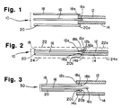
- FIG. 1 is an exploded sectional view of the gasketed membrane electrode assembly prior to consolidation into a unitary assembly.
- FIG. 2 is a sectional view of the gasketed membrane electrode assembly of FIG. 1 after consolidation into a unitary assembly, and interposed between electrically conductive separator plates to form a fuel cell unit.
- FIG. 3 is an exploded sectional view of a second embodiment of a gasketed membrane electrode assembly prior to consolidation into a unitary assembly.
- FIG. 4 is a sectional view of the gasketed membrane electrode assembly of FIG. 3 after consolidation into a unitary assembly, and interposed between electrically conductive separator plates to form a fuel cell unit.
- FIG. 5 is an exploded sectional view of a third embodiment of a gasketed membrane electrode assembly prior to consolidation into a unitary assembly.
- FIG. 6 is a sectional view of the gasketed membrane electrode assembly of FIG. 5 after consolidation into a unitary assembly, and interposed between electrically conductive separator plates to form a fuel cell unit.
- FIG. 7 is an exploded sectional view of a fourth embodiment of a gasketed membrane electrode assembly prior to consolidation into a unitary assembly.
- FIG. 8 is a sectional view of the gasketed membrane electrode assembly of FIG. 7 after consolidation into a unitary assembly, and interposed between electrically conductive separator plates to form a fuel cell unit.
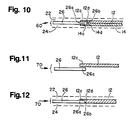
- FIG. 9 is an exploded sectional view of a gasketed humidification membrane assembly prior to consolidation into a unitary assembly.
- FIG. 10 is a sectional view of the gasketed humidification membrane assembly of FIG. 9 after consolidation into a unitary assembly, and interposed between separator plates.
- FIG. 11 is an exploded sectional view of a second embodiment of a gasketed humidification membrane assembly prior to consolidation into a unitary assembly.
- FIG. 12 is a sectional view of the gasketed humidification membrane assembly of FIG. 11 after consolidation into a unitary assembly, and interposed between separator plates.
- FIG. 1 of the drawings a gasketed membrane electrode assembly 10 prior to consolidation into a single unitary assembly is shown.
- the gasketing material layers 12, 14 are placed on either side of the ion exchange membrane 16.
- Carbon fiber paper based electrodes 18, 20 form the top and bottom portions of the five layer gasketed membrane electrode assembly.
- electrode 18 is the anode and electrode 20 is the cathode.
- the portion 16a of the membrane 16 that is interposed between the layers of gasketing material 12, 14 is kept to a minimum, being only large enough to ensure a good seal between the membrane and the gasketing material.
- the portions 18a, 20a of the electrodes 18, 20 that overlap the gasketing material need only be large enough to ensure a good seal between the electrodes and the gasketing material.
- FIG. 2 shows the gasketed membrane electrode assembly 10 after consolidation into a single unit and interposed between electrically conductive separator plates 22, 24. Consolidation is achieved either by the application of heat and pressure (where the gasketing material is a thermoplastic elastomer) or by employing a cold bonding process. Cold bonding involves the employment of solvents or adhesives to join the layers together.
- portions 12a, 14a of the gasketing material layers 12, 14 are compressed between the membrane 16 and the electrodes 18, 20.
- Other portions 12b, 14b of the gasketing material abut the edge 16b of membrane 16 and the edges 18b, 20b of the electrodes 18, 20.
- the portions 12b, 14b of the gasketing material layers 12, 14 that abut the edges of the membrane and the electrodes form a seal which effectively prevents leakage of reactant gases and reaction products into the atmosphere from between the separator plates 22, 24.
- the gasketing material By forming a seal around the edge 16b of the membrane 16, the gasketing material also prevents the membrane 16 from being exposed to the environment and thus dehydrating.
- the gasketing material layers 12, 14 are interposed between the peripheral portions 22a, 24a of the electrically conductive separator plates 22, 24, substantially filling the space between the electrically conductive separator plates 22, 24 around the periphery of the membrane electrode assembly 10, thus functioning as a gasket between the electrically conductive separator plates 22, 24.
- the gasketing material layers 12, 14 may be formed of an elastomeric material suitable for in situ molding.
- a nonhydrophilic thermoplastic elastomer is preferred.
- Such preferred gasketing materials include Shell's KRATON brand butadiene/styrene copolymer and Monsanto's SANTOPRENE brand ethylene/propylene copolymer.
- the ion exchange membrane 16 in its protonated form is acidic.
- Using an inert gasketing material instead of the ion exchange membrane 16 to fill the space between the peripheral portions 22a, 24a of the electrically conductive separator plates 22, 24 eliminates contact between the ion exchange membrane 16 and the separator plates 22, 24. As a result, there is less or no corrosive attack on the separator plates by the acidic membrane. Also, the electrochemically active portion of the ion exchange membrane 16 is more protected from contamination originating at the peripheral portions 22a, 24a of the electrically conductive separator plates 22, 24.
- FIG. 3 shows a second embodiment of a gasketed membrane electrode assembly, designated generally as 30.
- the ion exchange membrane 16 is interposed between the anode 18 and the cathode 20.
- a portion 16c of the membrane 16 extends beyond the edges 18b, 20b of the electrodes 18, 20.
- the three layer electrode-membrane-electrode assembly is interposed between layers of gasketing material 12, 14 such that portions 12c, 14c of the gasketing material layers 12, 14 overlap the respective portions 18c, 20c of the electrodes 18, 20 on the sides facing away from the membrane 16.
- FIG. 4 shows the gasketed membrane electrode assembly 30 of FIG. 3 after it has been consolidated into a single unit and interposed between electrically conductive separator plates 22, 24.
- the gasketing material layers 12, 14 form a seal against the edges 18b, 20b of the electrodes 18, 20 and the edge 16b of the membrane 16.
- the portions 12c, 14c of the gasketing material layers 12, 14 overlapping the electrodes 18, 20 are now compressed between the respective electrodes 18, 20 and the respective separator plates 22, 24.
- the gasketing material layers 12, 14 substantially occupy the space between the electrically conductive separator plates 22, 24 around the periphery of the membrane electrode assembly 30, functioning as a gasket between the separator plates 22, 24.
- FIG. 5 illustrates a third embodiment of a gasketed membrane electrode assembly, designated generally as 40, in which the ion exchange membrane 16 is interposed between the anode 18 and the cathode 20 and the three layer electrode-membrane-electrode assembly is arranged in a stepped arrangement. As shown in FIG. 5, the edge 16b of the membrane 16 extends beyond the edge 18b of the anode 18 and the edge 20b of the cathode 20 extends beyond the edge 16b of the membrane 16.
- a single layer of gasketing material 12 is positioned on top of the electrode-membrane-electrode assembly such that a portion 12c of the gasketing material 12 overlaps a portion 18c of the anode 18 on the side of the anode 18 facing away from the membrane 16.
- FIG. 6 shows the gasketed membrane electrode assembly 40 of FIG. 5 after it has been consolidated into a single unit and interposed between electrically conductive separator plates 22, 24.
- the gasketing material layer 12 forms a seal against the edges 18b, 20b of the electrodes 18, 20 and the edge 16b of the membrane 16.
- the portion 12c of the gasketing material layer 12 overlapping the anode 18 is now compressed between the anode 18 and the separator plate 22.
- the gasketing material layer 12 substantially occupies the space between the electrically conductive separator plates 22, 24 around the periphery of the membrane electrode assembly 40, thereby forming an effective seal between the separator plates 22, 24.
- FIG. 7 illustrates a fourth embodiment of a gasketed membrane electrode assembly, designated generally as 50.
- the membrane 16 is interposed between the anode 18 and the cathode 20 and the three layer electrode-membrane-electrode assembly is arranged in a stepped arrangement.
- the anode 18 and the cathode 20 are reversed from their positions in the third embodiment.
- the edge 16b of the membrane 16 extends beyond the edge 20b of the cathode 20
- the edge 18b of the anode 18 extends beyond the edge 16b of the membrane 16.
- a single layer of gasketing material 12 is positioned on top of the electrode-membrane-electrode assembly such that a portion 12c of the gasketing material layer 12 overlaps a portion 20c of the cathode 20 on the side of the cathode 20 facing away from the membrane 16.
- FIG. 8 shows the gasketed membrane electrode assembly 50 of FIG. 7 after it has been consolidated into a single unit and interposed between electrically conductive separator plates 22, 24.
- the gasketing material layer 12 forms a seal against the edges 18b, 20b of the electrodes 18, 20 and the edge 16b of the membrane 16.
- the portion 12c of the gasketing material 12 overlapping the cathode 20 is now compressed between the cathode 20 and the separator plate 22.
- the table below shows the potential cost savings of the present gasketed membrane electrode assembly over conventional membrane electrode assemblies in which the membrane itself serves as the gasket between the separator plates.
- the present gasketed membrane electrode assembly (referred to as GMEA in the table) requires only 42 square inches of membrane, compared to 81 square inches for the conventional assembly.
- the present gasketed membrane electrode assembly 86% of the membrane is utilized as a cation exchange site, compared to only 44% for the conventional assembly.
- the present gasketed membrane electrode assembly results in a cost savings of about $64 per cell, or about $2,251 per 35 cell stack, representing a 48% savings on the membrane cost for a 35 cell stack.
- a gasketed membrane electrode assembly that reduces the cost of solid polymer fuel cells by reducing the amount of membrane material needed in the cell.
- FIG. 9 illustrates a gasketed membrane assembly 60 for use in the humidification portion of a fuel cell, prior to consolidation into a unitary assembly.
- the gasketed humidification membrane assembly 60 is comprised of a water permeable membrane 26 interposed between layers of gasketing material 12, 14 such that portions 12c, 14c of the gasketing material layers 12, 14 overlap the periphery 26a of the membrane 26.
- the layers of gasketing material 12, 14 extend from the periphery 26a of the water permeable membrane 26 in a direction away from the central region of the membrane 26.
- FIG. 10 shows the gasketed humidification membrane assembly 60 of FIG. 9 after it has been consolidated into a single unit and interposed between separator plates 22, 24.
- the portion 12c of the gasketing material layer 12 overlapping the membrane is now compressed between the membrane 26 and the separator plate 22, and the portion 14c of gasketing material layer 14 overlapping the membrane 26 is now compressed between the membrane 26 and the separator plate 24.
- Other portions 12d, 14d of the gasketing material layers 12, 14 abut the edge 26b of the water permeable membrane 26, forming a seal which effectively prevents leakage of gases into the atmosphere from between the separator plates 22, 24.
- FIG. 11 illustrates another embodiment of a gasketed humidification membrane assembly, designated generally as 70, prior to consolidation into a unitary assembly.
- the gasketed membrane assembly 70 is comprised of a water permeable membrane 26 and a layer of gasketing material 12 extending from the periphery 26a of the membrane 26 in a direction away from the central region of the membrane 26. A portion 12c of the gasketing layer 12 overlaps the periphery 26a of the membrane 26.
- FIG. 12 shows the gasketed humidification membrane assembly 70 of FIG. 11 after consolidation into a single unit and interposed between separator plates 22, 24.
- the portion 12c of the gasketing material layer 12 overlapping the water permeable membrane 26 is now compressed between the membrane 26 and the separator plate 22.
- a portion 12d of the gasketing material layer 12 abuts the edge 26b of the water permeable membrane 26, providing a seal which prevents gases from escaping into the atmosphere from between the separator plates 22, 24.
Landscapes
- Chemical & Material Sciences (AREA)
- Engineering & Computer Science (AREA)
- Chemical Kinetics & Catalysis (AREA)
- Electrochemistry (AREA)
- Sustainable Development (AREA)
- Life Sciences & Earth Sciences (AREA)
- Manufacturing & Machinery (AREA)
- Sustainable Energy (AREA)
- General Chemical & Material Sciences (AREA)
- Metallurgy (AREA)
- Organic Chemistry (AREA)
- Materials Engineering (AREA)
- Fuel Cell (AREA)
Abstract
Description
- This invention relates to electrochemical fuel cells, and, in particular, to a gasketed membrane electrode assembly for solid polymer electrolyte fuel cells.
- Solid polymer electrolyte fuel cells (SPFCs) have been shown to be reliable for generating electricity by the oxidation of a conventional fuel such as hydrogen. The long demonstrated life and relative simplicity of design make SPFCs particularly suitable for space and transportation applications.
- A single solid polymer electrolyte fuel cell comprises an ion exchange membrane separating an anode and a cathode, all of which is interposed between electrically conductive separator plates. A plurality of cells make up an SPFC stack.
- The anode and cathode in a solid polymer electrolyte fuel cell are planar in configuration, and are normally formed of porous electrically conductive sheet material such as carbon fiber paper. A suitable catalytic material, such as finely divided platinum, is typically applied to the surfaces of the anode and cathode facing the membrane to render the portions containing the catalytic material electrochemically active.
- Typically, flow field grooves are molded or machined on the surfaces of the electrically conductive separator plates facing the anode or the cathode to accommodate reactant fluid distribution and reaction product collection and elimination.
- In conventional SPFCs, the solid polymer membrane serves at least three functions. First, the membrane separates the anode from the cathode. Hydrogen fuel is oxidized at the anode to form protons (hydrogen cations), which migrate across the membrane to the cathode. Oxygen is reduced at the cathode and reacts with the migrated hydrogen cations to form water. Second, the electrochemically active region of the membrane serves as a medium through which the hydrogen cations migrate to the cathode. Third, the portion of the membrane extending beyond the electrochemically active region into the space between the separator plates serves as a gasket to prevent reactant gases from escaping to the atmosphere from between the separator plates.
- An advantage of solid polymer membranes is their immiscible nature, which facilitates the separation and removal of reaction products. Other advantages of solid polymer membranes include their relative insensitivity to differential pressure between the anode and the cathode, their chemical stability and their non-corrosiveness.
- A disadvantage of solid polymer membranes is their high cost. This cost is even greater in SPFCs where the membrane itself is used as a gasket, because more membrane area is required. Where the membrane serves as a gasket, the membrane must extend substantially beyond the electrochemically active region of the membrane and into the space between the graphite separator plates. That portion extending beyond the active region adds to the overall cost of the SPFC, but is not utilized as a medium for cation migration.
- Examples of SPFCs in which the solid polymer membrane serves as a gasket include those developed and described by United Technologies Corporation (UTC) for zero gravity applications, rigorous naval applications, and extraterrestrial surface applications. In such UTC fuel cells, a portion of the solid polymer membrane is interposed between the anode frame and the cathode frame and functions as a gasket, preventing reactant gases from escaping to the atmosphere.
- There are several disadvantages to configurations employing the membrane itself as a gasket. As already noted, the cost of solid polymer membranes is high, and using a portion of the membrane as a gasket requires a larger membrane area, thus increasing the overall cost of the fuel cell. Use of the membrane as a gasket also exposes the membrane edge to the atmosphere, thereby allowing the evaporation of water, required for effective cation transport, from the membrane. In addition, the gasketing portion of the membrane is in contact with the separator plates at about 70°C - 80°C (158°F - 176°F), thus further promoting the dehydration of the membrane edge and possible degradation of the membrane's physical and chemical properties. For example, contaminants such as various metal ions can leach out from the separator plates and diffuse through the portion of the membrane acting as a gasket to the electrochemically active portion of the membrane, thus reducing the membrane's ability to act as an ion exchange medium. Another disadvantage of SPFCs in which the membrane serves as a gasket is that, where the membrane, in its protonated form, contacts the separator plates, the acidic membrane will corrode the separator plates.
- Cells which incorporate a gasket in addition to the membrane are described in FR-A-2410059 and US-A-3134697, FR-A-2410059 relates to an installation for the production of a gas, such as hydrogen gas, by the electrolysis of a liquid electrolyte. It comprises a series of alternately arranged electrodes and ion permeable membranes. Gaskets are provided at the periphery of the membranes and seal off the area between the electrodes. In this electrolytic cell, the gaskets do not extend beyond the periphery of the electrodes. US-A-3134697 describes a fuel cell comprising a pair of electrodes separated by a membrane. The electrodes and membrane are interposed between a pair of end plates. The assembly is connected together through the intermediary of gaskets located between the end plates so that spaces are formed between the electrodes and the end plates for the introduction of reagents into the spaces. In this cell, the gasket is not interposed between the electrodes and the membrane.
- It is therefore an object of the invention to provide a membrane electrode assembly for solid polymer fuel cells which minimizes the amount of membrane material in the fuel cell by employing a less expensive and more effective gasketing material at the periphery of the membrane, rather than employing the membrane itself as a gasket.
- It is a further object of the invention to provide a membrane electrode assembly in which exposure of the edges of the solid polymer membrane to the environment surrounding the fuel cell is avoided, thus preventing dehydration of the membrane.
- Another object of the invention is to provide a membrane electrode assembly in which a thinner, more electrochemically efficient membrane can be employed, since the gasketing function is performed by the gasketing material and not by the membrane itself.
- Still another object of the invention is to provide a membrane electrode assembly which minimizes or eliminates contact between the membrane and the separator plates, thus reducing any corrosive attack on the separator plates by the acidic membrane, and also reducing contamination of the membrane by contaminants originating in the separator plates.
- Further and additional objects will appear from the description, accompanying drawings, and appended claims.
- The foregoing and other objects are achieved by a gasketed membrane electrode assembly comprising an anode and a cathode, each planar in configuration and having an electrochemically active portion. An ion exchange membrane is interposed between the anode and the cathode. A first layer of gasketing material is interposed between the anode and the membrane. A second layer of gasketing material is interposed between the cathode and the membrane. Both layers of gasketing material extend from the periphery of the membrane in a direction away from the electrochemically active portion of the electrodes.
- In the preferred embodiment, the periphery of the membrane extends beyond the periphery of the electrodes. The membrane is preferably a solid polymer ion exchange membrane, typically a porous, sulfonated material. The preferred gasketing material is a nonhydrophilic thermoplastic elastomer.
- The gasketed membrane electrode assembly is preferably consolidated into a single unit by employing a cold bonding process or by the application of heat and pressure. In the preferred embodiment, the consolidated gasketed membrane electrode assembly is interposed between electrically conductive separator plates such that the gasketing material substantially occupies the space between the periphery of the separator plates, thereby forming a seal.
- The electrically conductive separator plates, sometimes referred to as flow field plates, contain flow channels for the transport of fluids to and from the membrane electrode assembly. The separator plates are preferably formed of graphite, but can also be formed of other suitable electrically conductive materials.
- In a second embodiment, the gasketed membrane electrode assembly comprises an anode, a cathode, and an ion exchange membrane interposed between the anode and the cathode. The entire anode-membrane-cathode assembly is interposed between layers of gasketing material. A first layer of gasketing material extends from the periphery of the anode on the side facing away from the membrane and in a direction away from the electrochemically active portion of the anode. A second layer of gasketing material extends from the periphery of the cathode on the side facing away from the membrane and in a direction away from the electrochemically active portion of the cathode.
- In another embodiment, the gasketed membrane electrode assembly comprises an anode, a cathode, and an ion exchange membrane interposed between the anode and the cathode. A layer of gasketing material extends from the periphery of the anode on the side facing away from the membrane and in a direction away from the electrochemically active portion of the anode. In this embodiment, the periphery of the cathode preferably extends beyond the periphery of the ion exchange membrane, and the periphery of the ion exchange membrane preferably extends beyond the periphery of the anode.
- In yet another embodiment, the gasketed membrane electrode assembly comprises a cathode, an anode, and an ion exchange membrane interposed between the anode and the cathode. A layer of gasketing material extends from the periphery of the cathode on the side facing away from the membrane and in a direction away from the electrochemically active portion of the cathode. In this embodiment, the periphery of the anode preferably extends beyond the periphery of the ion exchange membrane, and the periphery of the membrane extends beyond the periphery of the cathode.
- In another embodiment not according to the invention, the gasketed membrane assembly can be employed in the humidification portion of a fuel cell. Such a gasketed humidification membrane assembly comprises a water permeable membrane interposed between layers of gasketing material. The layers of gasketing material extend from the periphery of the membrane in a direction away from the central region of the membrane. The entire gasketed humidification membrane assembly is preferably interposed between separator plates, such that the gasketing material occupies the space between the periphery of the separator plates, thereby forming a seal.
- For a more complete understanding of the invention reference is made to the drawings wherein:
- FIG. 1 is an exploded sectional view of the gasketed membrane electrode assembly prior to consolidation into a unitary assembly.
- FIG. 2 is a sectional view of the gasketed membrane electrode assembly of FIG. 1 after consolidation into a unitary assembly, and interposed between electrically conductive separator plates to form a fuel cell unit.
- FIG. 3 is an exploded sectional view of a second embodiment of a gasketed membrane electrode assembly prior to consolidation into a unitary assembly.
- FIG. 4 is a sectional view of the gasketed membrane electrode assembly of FIG. 3 after consolidation into a unitary assembly, and interposed between electrically conductive separator plates to form a fuel cell unit.
- FIG. 5 is an exploded sectional view of a third embodiment of a gasketed membrane electrode assembly prior to consolidation into a unitary assembly.
- FIG. 6 is a sectional view of the gasketed membrane electrode assembly of FIG. 5 after consolidation into a unitary assembly, and interposed between electrically conductive separator plates to form a fuel cell unit.
- FIG. 7 is an exploded sectional view of a fourth embodiment of a gasketed membrane electrode assembly prior to consolidation into a unitary assembly.
- FIG. 8 is a sectional view of the gasketed membrane electrode assembly of FIG. 7 after consolidation into a unitary assembly, and interposed between electrically conductive separator plates to form a fuel cell unit.
- FIG. 9 is an exploded sectional view of a gasketed humidification membrane assembly prior to consolidation into a unitary assembly.
- FIG. 10 is a sectional view of the gasketed humidification membrane assembly of FIG. 9 after consolidation into a unitary assembly, and interposed between separator plates.
- FIG. 11 is an exploded sectional view of a second embodiment of a gasketed humidification membrane assembly prior to consolidation into a unitary assembly.
- FIG. 12 is a sectional view of the gasketed humidification membrane assembly of FIG. 11 after consolidation into a unitary assembly, and interposed between separator plates.
- Referring first to FIG. 1 of the drawings, a gasketed
membrane electrode assembly 10 prior to consolidation into a single unitary assembly is shown. As FIG. 1 illustrates, the gasketing material layers 12, 14 are placed on either side of theion exchange membrane 16. Carbon fiber paper basedelectrodes electrode 18 is the anode andelectrode 20 is the cathode. - The
portion 16a of themembrane 16 that is interposed between the layers ofgasketing material portions 18a, 20a of theelectrodes - FIG. 2 shows the gasketed
membrane electrode assembly 10 after consolidation into a single unit and interposed between electricallyconductive separator plates - Upon consolidation,
portions 12a, 14a of the gasketing material layers 12, 14 are compressed between themembrane 16 and theelectrodes Other portions 12b, 14b of the gasketing material abut theedge 16b ofmembrane 16 and theedges electrodes portions 12b, 14b of the gasketing material layers 12, 14 that abut the edges of the membrane and the electrodes form a seal which effectively prevents leakage of reactant gases and reaction products into the atmosphere from between theseparator plates - By forming a seal around the
edge 16b of themembrane 16, the gasketing material also prevents themembrane 16 from being exposed to the environment and thus dehydrating. - The gasketing material layers 12, 14 are interposed between the peripheral portions 22a, 24a of the electrically
conductive separator plates conductive separator plates membrane electrode assembly 10, thus functioning as a gasket between the electricallyconductive separator plates - The gasketing material layers 12, 14 may be formed of an elastomeric material suitable for in situ molding. A nonhydrophilic thermoplastic elastomer is preferred. Such preferred gasketing materials include Shell's KRATON brand butadiene/styrene copolymer and Monsanto's SANTOPRENE brand ethylene/propylene copolymer.
- The
ion exchange membrane 16 in its protonated form is acidic. Using an inert gasketing material instead of theion exchange membrane 16 to fill the space between the peripheral portions 22a, 24a of the electricallyconductive separator plates ion exchange membrane 16 and theseparator plates ion exchange membrane 16 is more protected from contamination originating at the peripheral portions 22a, 24a of the electricallyconductive separator plates - FIG. 3 shows a second embodiment of a gasketed membrane electrode assembly, designated generally as 30. In FIG. 3, the
ion exchange membrane 16 is interposed between theanode 18 and thecathode 20. Aportion 16c of themembrane 16 extends beyond theedges electrodes gasketing material portions respective portions electrodes membrane 16. - FIG. 4 shows the gasketed
membrane electrode assembly 30 of FIG. 3 after it has been consolidated into a single unit and interposed between electricallyconductive separator plates edges electrodes edge 16b of themembrane 16. Theportions electrodes respective electrodes respective separator plates conductive separator plates membrane electrode assembly 30, functioning as a gasket between theseparator plates - FIG. 5 illustrates a third embodiment of a gasketed membrane electrode assembly, designated generally as 40, in which the
ion exchange membrane 16 is interposed between theanode 18 and thecathode 20 and the three layer electrode-membrane-electrode assembly is arranged in a stepped arrangement. As shown in FIG. 5, theedge 16b of themembrane 16 extends beyond theedge 18b of theanode 18 and theedge 20b of thecathode 20 extends beyond theedge 16b of themembrane 16. A single layer ofgasketing material 12 is positioned on top of the electrode-membrane-electrode assembly such that aportion 12c of thegasketing material 12 overlaps aportion 18c of theanode 18 on the side of theanode 18 facing away from themembrane 16. - FIG. 6 shows the gasketed
membrane electrode assembly 40 of FIG. 5 after it has been consolidated into a single unit and interposed between electricallyconductive separator plates gasketing material layer 12 forms a seal against theedges electrodes edge 16b of themembrane 16. Theportion 12c of thegasketing material layer 12 overlapping theanode 18 is now compressed between theanode 18 and theseparator plate 22. Also, as in the embodiments of FIGS. 2 and 4, thegasketing material layer 12 substantially occupies the space between the electricallyconductive separator plates membrane electrode assembly 40, thereby forming an effective seal between theseparator plates - FIG. 7 illustrates a fourth embodiment of a gasketed membrane electrode assembly, designated generally as 50. In this embodiment, as in the third embodiment, the
membrane 16 is interposed between theanode 18 and thecathode 20 and the three layer electrode-membrane-electrode assembly is arranged in a stepped arrangement. However, theanode 18 and thecathode 20 are reversed from their positions in the third embodiment. Thus, theedge 16b of themembrane 16 extends beyond theedge 20b of thecathode 20, and theedge 18b of theanode 18 extends beyond theedge 16b of themembrane 16. A single layer ofgasketing material 12 is positioned on top of the electrode-membrane-electrode assembly such that aportion 12c of thegasketing material layer 12 overlaps aportion 20c of thecathode 20 on the side of thecathode 20 facing away from themembrane 16. - FIG. 8 shows the gasketed
membrane electrode assembly 50 of FIG. 7 after it has been consolidated into a single unit and interposed between electricallyconductive separator plates gasketing material layer 12 forms a seal against theedges electrodes edge 16b of themembrane 16. Theportion 12c of thegasketing material 12 overlapping thecathode 20 is now compressed between thecathode 20 and theseparator plate 22. - The table below shows the potential cost savings of the present gasketed membrane electrode assembly over conventional membrane electrode assemblies in which the membrane itself serves as the gasket between the separator plates. In order to provide an electrochemically active area of 36 square inches, the present gasketed membrane electrode assembly (referred to as GMEA in the table) requires only 42 square inches of membrane, compared to 81 square inches for the conventional assembly. With the present gasketed membrane electrode assembly, 86% of the membrane is utilized as a cation exchange site, compared to only 44% for the conventional assembly. At a cost of $1.64 per square inch of membrane, the present gasketed membrane electrode assembly results in a cost savings of about $64 per cell, or about $2,251 per 35 cell stack, representing a 48% savings on the membrane cost for a 35 cell stack.

- Thus, a gasketed membrane electrode assembly is provided that reduces the cost of solid polymer fuel cells by reducing the amount of membrane material needed in the cell.
- FIG. 9 illustrates a
gasketed membrane assembly 60 for use in the humidification portion of a fuel cell, prior to consolidation into a unitary assembly. The gasketedhumidification membrane assembly 60 is comprised of a waterpermeable membrane 26 interposed between layers ofgasketing material portions periphery 26a of themembrane 26. The layers ofgasketing material periphery 26a of the waterpermeable membrane 26 in a direction away from the central region of themembrane 26. - FIG. 10 shows the gasketed
humidification membrane assembly 60 of FIG. 9 after it has been consolidated into a single unit and interposed betweenseparator plates portion 12c of thegasketing material layer 12 overlapping the membrane is now compressed between themembrane 26 and theseparator plate 22, and theportion 14c ofgasketing material layer 14 overlapping themembrane 26 is now compressed between themembrane 26 and theseparator plate 24.Other portions edge 26b of the waterpermeable membrane 26, forming a seal which effectively prevents leakage of gases into the atmosphere from between theseparator plates - FIG. 11 illustrates another embodiment of a gasketed humidification membrane assembly, designated generally as 70, prior to consolidation into a unitary assembly. The
gasketed membrane assembly 70 is comprised of a waterpermeable membrane 26 and a layer ofgasketing material 12 extending from theperiphery 26a of themembrane 26 in a direction away from the central region of themembrane 26. Aportion 12c of thegasketing layer 12 overlaps theperiphery 26a of themembrane 26. - FIG. 12 shows the gasketed
humidification membrane assembly 70 of FIG. 11 after consolidation into a single unit and interposed betweenseparator plates portion 12c of thegasketing material layer 12 overlapping the waterpermeable membrane 26 is now compressed between themembrane 26 and theseparator plate 22. Aportion 12d of thegasketing material layer 12 abuts theedge 26b of the waterpermeable membrane 26, providing a seal which prevents gases from escaping into the atmosphere from between theseparator plates - Of course, many modifications and other embodiments of the invention will be recognized by one skilled in the art in view of the foregoing teachings.
Claims (16)
- A gasketed membrane electrode assembly for use in the electrochemically active portion of a fuel cell comprising:a. an anode having an electrochemically active portion;b. a cathode having an electrochemically active portion;c. an ion exchange membrane interposed between said anode and said cathode;d. a first layer of gasketing material interposed between said anode and said membrane, said first layer extending from the periphery of said membrane and from the periphery of said anode in a direction away from the electrochemically active portion of said anode; ande. a second layer of gasketing material interposed between said cathode and said membrane, said second layer extending from the periphery of said membrane and from the periphery of said cathode in a direction away from the electrochemically active portion of said cathode.
- The gasketed membrane electrode assembly of claim 1 wherein the periphery of said membrane extends beyond the periphery of said anode and said cathode.
- The gasketed membrane electrode assembly of claim 1 wherein said gasketing material is formed from a nonhydrophilic thermoplastic elastomer.
- The gasketed membrane electrode assembly of claim 1 wherein said assembly is interposed between a pair of electrically conductive separator plates.
- A gasketed membrane electrode assembly for use in the electrochemically active portion of a fuel cell comprising:a. an anode having an electrochemically active portion;b. a cathode having an electrochemically active portion;c. an ion exchange membrane interposed between said anode and said cathode;d. a first layer of gasketing material extending from the periphery of said anode on the side facing away from said membrane and in a direction away from the electrochemically active portion of said anode; ande. a second layer of gasketing material extending from the periphery of said cathode on the side facing away from said membrane and in a direction away from the electrochemically active portion of said cathode,
said first and second layers of gasketing material forming a seal against the peripheral edges of said anode and said cathode, respectively, and the peripheral edge of said membrane. - The gasketed membrane electrode assembly of claim 5 wherein the periphery of said membrane extends beyond the periphery of said anode and said cathode.
- The gasketed membrane electrode assembly of claim 5 wherein said gasketing material is formed from a nonhydrophilic thermoplastic elastomer.
- The gasketed membrane electrode assembly of claim 5 wherein said assembly is interposed between a pair of electrically conductive separator plates.
- A gasketed membrane electrode assembly for use in the electrochemically active portion of a fuel cell comprising:a. an anode having an electrochemically active portion;b. a cathode having an electrochemically active portion;c. an ion exchange membrane interposed between said anode and said cathode; andd. a layer of gasketing material extending from the periphery of said anode on the side facing away from said membrane and in a direction away from the electrochemically active portion of said anode,
said layer of gasketing material forming a seal against the peripheral edges of said anode and said cathode and the peripheral edge of said membrane. - The gasketed membrane electrode assembly of claim 9 wherein the periphery of said cathode extends beyond the periphery of said ion exchange membrane, and the periphery of said ion exchange membrane extends beyond the periphery of said anode.
- The gasketed membrane electrode assembly of claim 9 wherein said gasketing material is formed from a nonhydrophilic thermoplastic elastomer.
- The gasketed membrane electrode assembly of claim 9 wherein said assembly is interposed between a pair of electrically conductive separator plates.
- A gasketed membrane electrode assembly for use in the electrochemically active portion of a fuel cell comprising:a. an anode having an electrochemically active portion;b. a cathode having an electrochemically active portion;c. an ion exchange membrane interposed between said anode and said cathode; andd. a layer of gasketing material extending from the periphery of said cathode on the side facing away from said membrane and in a direction away from the electrochemically active portion of said cathode,
said layer of gasketing material forming a seal against the peripheral edges of said anode and said cathode and the peripheral edge of said membrane. - The gasketed membrane electrode assembly of claim 13 wherein the periphery of said anode extends beyond the periphery of said ion exchange membrane, and the periphery of said ion exchange membrane extends beyond the periphery of said cathode.
- The gasketed membrane electrode assembly of claim 13 wherein said gasketing material is formed from a nonhydrophilic thermoplastic elastomer.
- The gasketed membrane electrode assembly of claim 13 wherein said assembly is interposed between a pair of electrically conductive separator plates.
Applications Claiming Priority (3)
| Application Number | Priority Date | Filing Date | Title |
|---|---|---|---|
| US71009091A | 1991-06-04 | 1991-06-04 | |
| US710090 | 1991-06-04 | ||
| PCT/CA1992/000231 WO1992022096A2 (en) | 1991-06-04 | 1992-06-01 | Gasketed membrane electrode assembly for electrochemical fuel cells |
Publications (2)
| Publication Number | Publication Date |
|---|---|
| EP0586461A1 EP0586461A1 (en) | 1994-03-16 |
| EP0586461B1 true EP0586461B1 (en) | 1995-09-13 |
Family
ID=24852585
Family Applications (1)
| Application Number | Title | Priority Date | Filing Date |
|---|---|---|---|
| EP92910726A Expired - Lifetime EP0586461B1 (en) | 1991-06-04 | 1992-06-01 | Gasketed membrane electrode assembly for electrochemical fuel cells |
Country Status (7)
| Country | Link |
|---|---|
| US (1) | US5464700A (en) |
| EP (1) | EP0586461B1 (en) |
| JP (1) | JP3245161B2 (en) |
| AU (1) | AU664703B2 (en) |
| CA (1) | CA2102695C (en) |
| DE (1) | DE69204834T2 (en) |
| WO (1) | WO1992022096A2 (en) |
Cited By (3)
| Publication number | Priority date | Publication date | Assignee | Title |
|---|---|---|---|---|
| US7005208B2 (en) | 2000-10-18 | 2006-02-28 | Honda Giken Kogyo Kabushiki Kaisha | Method for mounting seals for fuel cell and fuel cell |
| US8021796B2 (en) | 2002-09-30 | 2011-09-20 | Umicore Ag & Co. Kg | Catalyst-coated ionomer membrane with protective film layer and membrane-electrode-assembly made thereof |
| DE102010063254A1 (en) | 2010-12-16 | 2012-06-21 | FuMA-Tech Gesellschaft für funktionelle Membranen und Anlagentechnologie mbH | Membrane electrode assembly with two cover layers |
Families Citing this family (149)
| Publication number | Priority date | Publication date | Assignee | Title |
|---|---|---|---|---|
| US6037075A (en) * | 1996-11-26 | 2000-03-14 | United Technologies Corporation | Electrically non-conductive plate structures and high pressure electrochemical cell devices employing same |
| US5804326A (en) * | 1996-12-20 | 1998-09-08 | Ballard Power Systems Inc. | Integrated reactant and coolant fluid flow field layer for an electrochemical fuel cell |
| DE19703214C2 (en) | 1997-01-29 | 2003-10-30 | Proton Motor Fuel Cell Gmbh | Membrane electrode unit with integrated sealing edge and process for its manufacture |
| US6423439B1 (en) | 1997-07-16 | 2002-07-23 | Ballard Power Systems Inc. | Membrane electrode assembly for an electrochemical fuel cell |
| US6337120B1 (en) | 1998-06-26 | 2002-01-08 | Nok Corporation | Gasket for layer-built fuel cells and method for making the same |
| US6187466B1 (en) | 1998-07-23 | 2001-02-13 | International Fuel Cells Corporation | Fuel cell with water capillary edge seal |
| US6306530B1 (en) | 1998-08-27 | 2001-10-23 | International Fuel Cells Llc | System for preventing gas pocket formation in a PEM coolant flow field |
| US6207312B1 (en) | 1998-09-18 | 2001-03-27 | Energy Partners, L.C. | Self-humidifying fuel cell |
| US6159628A (en) * | 1998-10-21 | 2000-12-12 | International Fuel Cells Llc | Use of thermoplastic films to create seals and bond PEM cell components |
| US6020083A (en) * | 1998-10-30 | 2000-02-01 | International Fuel Cells Llc | Membrane electrode assembly for PEM fuel cell |
| US6387557B1 (en) | 1998-10-21 | 2002-05-14 | Utc Fuel Cells, Llc | Bonded fuel cell stack assemblies |
| WO2000026979A1 (en) * | 1998-10-30 | 2000-05-11 | Siemens Aktiengesellschaft | Frame element for a laminated pem fuel cell and production method thereof |
| US6399234B2 (en) | 1998-12-23 | 2002-06-04 | Utc Fuel Cells, Llc | Fuel cell stack assembly with edge seal |
| AU3234200A (en) * | 1999-03-10 | 2000-09-28 | Flexfab Horizons International, Inc. | Fuel cell gasket assembly and method of assembling fuel cells |
| DE19926027A1 (en) | 1999-05-28 | 2000-11-30 | Heliocentris Energiesysteme | Membrane electrode unit with integrated sealing edge |
| US6235166B1 (en) | 1999-06-08 | 2001-05-22 | E-Cell Corporation | Sealing means for electrically driven water purification units |
| CN1167628C (en) | 1999-06-08 | 2004-09-22 | E-Cell公司 | Sealing device for electric drive water purification unit and manufacturing method thereof |
| US6231053B1 (en) | 1999-06-11 | 2001-05-15 | Nok Corporation | Gasket for fuel cell |
| GB9915925D0 (en) * | 1999-07-08 | 1999-09-08 | Univ Loughborough | Flow field plates |
| US6355371B1 (en) | 1999-08-27 | 2002-03-12 | Plug Power Inc. | Profiled fuel cell flow plate gasket |
| US6261711B1 (en) | 1999-09-14 | 2001-07-17 | Plug Power Inc. | Sealing system for fuel cells |
| JP4576646B2 (en) * | 1999-09-30 | 2010-11-10 | アイシン精機株式会社 | Fuel cell |
| CA2345852C (en) | 2000-05-02 | 2008-11-18 | Honda Giken Kogyo Kabushiki Kaisha | Fuel cell having sealant for sealing a solid polymer electrolyte membrane |
| JP3648128B2 (en) | 2000-05-02 | 2005-05-18 | 本田技研工業株式会社 | Fuel cell |
| JP3866050B2 (en) | 2000-05-02 | 2007-01-10 | 本田技研工業株式会社 | Fuel cell |
| JP3505708B2 (en) * | 2000-06-12 | 2004-03-15 | 本田技研工業株式会社 | Single cell for polymer electrolyte fuel cell, method for manufacturing the same, polymer electrolyte fuel cell, and method for regenerating the same |
| KR100750021B1 (en) * | 2000-06-29 | 2007-08-16 | 엔오케이 가부시키가이샤 | Component parts for fuel cells |
| DE10048871A1 (en) * | 2000-07-14 | 2002-03-14 | Freudenberg Carl | Static elastomeric joint for water pump, cam cover, wing nut, carburetor, fuel valve, hoses, etc., has compressible elastomeric element in cavity formed between two stops on support surface |
| US6861171B1 (en) | 2000-11-27 | 2005-03-01 | Freudenberg-Nok General Partnership | Gasket assembly |
| US6797422B2 (en) | 2001-01-25 | 2004-09-28 | Gas Technology Institute | Air-breathing direct methanol fuel cell with metal foam current collectors |
| JP4043724B2 (en) * | 2001-02-14 | 2008-02-06 | 本田技研工業株式会社 | Unit fuel cell and fuel cell stack manufacturing method |
| JP4530122B2 (en) * | 2001-03-09 | 2010-08-25 | Nok株式会社 | gasket |
| JP3830766B2 (en) | 2001-03-09 | 2006-10-11 | 本田技研工業株式会社 | Fuel cell and fuel cell stack |
| US7297432B2 (en) * | 2001-03-09 | 2007-11-20 | Honda Giken Kogyo Kabushiki Kaisha | Fuel cell and fuel cell stack |
| US7226686B2 (en) | 2001-04-23 | 2007-06-05 | Nok Corporation | Fuel cell and method of manufacturing the fuel cell |
| GB0112021D0 (en) * | 2001-05-17 | 2001-07-11 | Johnson Matthey Plc | Substrate |
| JP5208338B2 (en) * | 2001-06-29 | 2013-06-12 | 本田技研工業株式会社 | Electrolyte membrane / electrode structure and fuel cell |
| JP4316164B2 (en) * | 2001-07-10 | 2009-08-19 | 本田技研工業株式会社 | Membrane / electrode structure and fuel cell |
| CA2451111C (en) * | 2001-07-11 | 2010-09-07 | Akiyoshi Machida | Method of coating fuel cell separator with seal material |
| JP4818546B2 (en) * | 2001-08-29 | 2011-11-16 | 本田技研工業株式会社 | Membrane / electrode structure |
| DE10152192B4 (en) * | 2001-10-23 | 2004-10-28 | Carl Freudenberg Kg | Process for manufacturing a carrier seal |
| US6844101B2 (en) * | 2002-01-04 | 2005-01-18 | Ballard Power Systems Inc. | Separator with fluid distribution features for use with a membrane electrode assembly in a fuel cell |
| DE50213646D1 (en) * | 2002-01-31 | 2009-08-13 | Sfc Smart Fuel Cell Ag | Sealing frame for fuel cell stacks |
| US7687181B2 (en) * | 2002-04-23 | 2010-03-30 | Protonex Technology Corporation | Channel-based electrochemical cassettes |
| WO2003096462A1 (en) | 2002-05-09 | 2003-11-20 | Anuvu, Inc. , A California Corporation | Electrochemical fuel cell comprised of a series of conductive compression gaskets and method of manufacture |
| US7087339B2 (en) * | 2002-05-10 | 2006-08-08 | 3M Innovative Properties Company | Fuel cell membrane electrode assembly with sealing surfaces |
| US7217471B2 (en) * | 2002-05-17 | 2007-05-15 | 3M Innovative Properties Company | Membrane electrode assembly with compression control gasket |
| US20030224237A1 (en) * | 2002-05-30 | 2003-12-04 | Vanderleeden Olen R. | Membrane electrode assembly for an electrochemical fuel cell |
| DE10235360A1 (en) * | 2002-08-02 | 2004-02-19 | Celanese Ventures Gmbh | Membrane electrode array, used in fuel cell, preferably high temperature fuel cell, has polyimide layer on both surfaces of polymer electrolyte membrane in contact with electrochemically active electrodes |
| JP4121340B2 (en) | 2002-09-04 | 2008-07-23 | 本田技研工業株式会社 | Fuel cell |
| US6861173B2 (en) * | 2002-10-08 | 2005-03-01 | Sompalli Bhaskar | Catalyst layer edge protection for enhanced MEA durability in PEM fuel cells |
| US7713644B2 (en) * | 2002-10-08 | 2010-05-11 | Gm Global Technology Operations, Inc. | Catalyst layer edge protection for enhanced MEA durability in PEM fuel cells |
| US8007949B2 (en) * | 2002-10-08 | 2011-08-30 | Bhaskar Sompalli | Edge-protected catalyst-coated diffusion media and membrane electrode assemblies |
| JP4135473B2 (en) * | 2002-11-07 | 2008-08-20 | 日産自動車株式会社 | Bipolar battery |
| US20040096723A1 (en) * | 2002-11-14 | 2004-05-20 | 3M Innovative Properties Company | Fuel cell gasket |
| CA2413467A1 (en) * | 2002-11-29 | 2004-05-29 | Ian Glenn Towe | Spacer for electrically driven membrane process apparatus |
| US6979383B2 (en) * | 2002-12-17 | 2005-12-27 | 3M Innovative Properties Company | One-step method of bonding and sealing a fuel cell membrane electrode assembly |
| FR2853142A1 (en) * | 2003-03-27 | 2004-10-01 | Commissariat Energie Atomique | METHOD FOR MANUFACTURING A COMPONENT COMPRISING AN ELECTRODE AND A RIGID SEAL AND COMPONENT OBTAINED THEREBY |
| CN1536698B (en) | 2003-04-02 | 2010-12-15 | 松下电器产业株式会社 | Electrolyte film structure for fuel cell, MEA structure and fuel cell |
| US7404884B2 (en) * | 2003-04-25 | 2008-07-29 | Siemens Water Technologies Holding Corp. | Injection bonded articles and methods |
| GB0314436D0 (en) * | 2003-06-20 | 2003-07-23 | Johnson Matthey Plc | Membrane electrode assembly |
| KR101146519B1 (en) | 2003-07-14 | 2012-07-05 | 우미코레 아게 운트 코 카게 | Membrane-electrode unit for electrolysis of water |
| US20050014056A1 (en) * | 2003-07-14 | 2005-01-20 | Umicore Ag & Co. Kg | Membrane electrode unit for electrochemical equipment |
| CA2477358C (en) * | 2003-08-22 | 2012-03-27 | Matsushita Electric Industrial Co., Ltd. | Polymer electrolyte fuel cell |
| GB0319780D0 (en) | 2003-08-22 | 2003-09-24 | Johnson Matthey Plc | Membrane electrode assembly |
| WO2005035247A2 (en) * | 2003-08-29 | 2005-04-21 | E.I. Dupont De Nemours And Company | Unitized membrane electrode assembly and process for its preparation |
| ITMI20031972A1 (en) * | 2003-10-14 | 2005-04-15 | Nuvera Fuel Cells Europ Srl | MEMBRANE FUEL CELL WITH STABLE OVER TIME OPERATION |
| US20050089746A1 (en) * | 2003-10-23 | 2005-04-28 | Ballard Power Systems Inc. | Prevention of membrane contamination in electrochemical fuel cells |
| JP4304101B2 (en) * | 2003-12-24 | 2009-07-29 | 本田技研工業株式会社 | Electrolyte membrane / electrode structure and fuel cell |
| KR100551809B1 (en) * | 2004-03-27 | 2006-02-13 | 현대자동차주식회사 | Single cell structure for fuel cell stack including composite gasket |
| EP1624515B1 (en) * | 2004-05-28 | 2008-12-17 | Du Pont Canada Inc. | Unitized electrochemical cell sub-assembly and the method of making the same |
| DE102004028141C5 (en) * | 2004-06-10 | 2015-11-19 | Elcomax Membranes Gmbh | Membrane Electrode Module (MEA) for a fuel cell and fuel cell stack |
| JP2006004677A (en) * | 2004-06-15 | 2006-01-05 | Toshiba Fuel Cell Power Systems Corp | Fuel cell |
| DE102004035309A1 (en) * | 2004-07-21 | 2006-02-16 | Pemeas Gmbh | Membrane electrode units and fuel cells with increased service life |
| US20060029850A1 (en) * | 2004-08-03 | 2006-02-09 | Peter Szrama | Fuel cell assembly with structural film |
| EP1624511A1 (en) * | 2004-08-05 | 2006-02-08 | Pemeas GmbH | Membrane electrode assemblies and fuel cells having increased durability |
| EP1624512A2 (en) * | 2004-08-05 | 2006-02-08 | Pemeas GmbH | Long-life membrane electrode assemblies |
| US7597983B2 (en) * | 2004-08-25 | 2009-10-06 | Gm Global Technology Operations, Inc. | Edge stress relief in diffusion media |
| KR101232396B1 (en) | 2004-08-30 | 2013-02-12 | 파나소닉 주식회사 | Membrane electrode assembly for solid polymer fuel cell and solid polymer fuel cell |
| GB0421254D0 (en) * | 2004-09-24 | 2004-10-27 | Johnson Matthey Plc | Membrane electrode assembly |
| US20060078781A1 (en) * | 2004-10-08 | 2006-04-13 | 3M Innovative Properties Company | Curable subgasket for a membrane electrode assembly |
| US7816058B2 (en) * | 2004-11-05 | 2010-10-19 | Gm Global Technology Operations, Inc. | Split architectures for MEA durability |
| EP1842259A4 (en) | 2004-12-28 | 2008-05-28 | Utc Fuel Cells Llc | Mea seal structure containing catalyzed layer |
| JP2008525971A (en) * | 2004-12-28 | 2008-07-17 | バラード パワー システムズ インコーポレイティド | Membrane electrode assembly for improving fuel cell performance |
| JP2006294293A (en) * | 2005-04-06 | 2006-10-26 | Toyota Motor Corp | Fuel cell |
| US20090035634A1 (en) * | 2005-05-31 | 2009-02-05 | Nissan Motor Co., Ltd. | Electrolyte Membrane-Electrode Assembly And Method For Production Thereof |
| JP5326189B2 (en) * | 2005-05-31 | 2013-10-30 | 日産自動車株式会社 | Electrolyte membrane-electrode assembly and method for producing the same |
| JP5166690B2 (en) * | 2005-06-02 | 2013-03-21 | 三菱重工業株式会社 | Solid polymer electrolyte fuel cell |
| FR2887686B1 (en) | 2005-06-28 | 2010-08-13 | Peugeot Citroen Automobiles Sa | SEAL AND FUEL CELL COMPRISING SUCH A SEAL APPOSE TO BIPOLAR PLATES |
| DE102005038195A1 (en) * | 2005-08-12 | 2007-02-15 | Pemeas Gmbh | Improved membrane electrode assemblies and fuel cells with long life |
| US20070042256A1 (en) * | 2005-08-18 | 2007-02-22 | Valentine Seth D | Gas crossover barrier with electrochemical conversion cell membrane |
| JP5194346B2 (en) * | 2005-08-31 | 2013-05-08 | 日産自動車株式会社 | Electrolyte membrane-electrode assembly |
| US7368200B2 (en) * | 2005-12-30 | 2008-05-06 | Tekion, Inc. | Composite polymer electrolyte membranes and electrode assemblies for reducing fuel crossover in direct liquid feed fuel cells |
| US7955750B2 (en) * | 2006-02-21 | 2011-06-07 | GM Global Technology Operations LLC | Controlled electrode overlap architecture for improved MEA durability |
| GB2437994A (en) * | 2006-05-13 | 2007-11-14 | Intelligent Energy Ltd | Gaskets for fuel cells |
| JP4978881B2 (en) * | 2006-06-26 | 2012-07-18 | トヨタ自動車株式会社 | Fuel cell |
| US20080107945A1 (en) * | 2006-11-08 | 2008-05-08 | Gm Global Technology Operations, Inc. | Fuel cell substrate with an overcoat |
| JP5186754B2 (en) * | 2006-11-14 | 2013-04-24 | トヨタ自動車株式会社 | Fuel cell |
| US20080118802A1 (en) * | 2006-11-16 | 2008-05-22 | Peter Szrama | Fully Catalyzed Membrane Assembly With Attached Border |
| US7794864B2 (en) * | 2007-04-13 | 2010-09-14 | Panasonic Corporation | Fuel cell module, fuel cell, and method of manufacturing fuel cell module |
| DE102007024959A1 (en) * | 2007-05-30 | 2008-12-04 | Linde Medical Devices Gmbh | Seal for electrode of e.g. fuel cell, has electrode with expanded material, which is completely surrounded by sealing material in electrode sealing area, where sealing material forms flat sealing surfaces at side surfaces of electrode |
| US8642230B2 (en) * | 2007-06-11 | 2014-02-04 | Panasonic Corporation | Electrode-membrane-frame assembly for fuel cell, polyelectrolyte fuel cell and manufacturing method therefor |
| US20090004543A1 (en) * | 2007-06-27 | 2009-01-01 | Seungsoo Jung | Membrane electrode assemblies for fuel cells and methods of making |
| JP5266734B2 (en) * | 2007-11-26 | 2013-08-21 | 大日本印刷株式会社 | Electrolyte membrane-catalyst layer assembly with reinforcing sheet, electrolyte membrane-electrode assembly with reinforcing sheet, solid polymer fuel cell, and method for producing electrolyte membrane-catalyst layer assembly with reinforcing sheet |
| JP5430099B2 (en) * | 2007-09-27 | 2014-02-26 | 大日本印刷株式会社 | Electrolyte membrane-electrode assembly and solid polymer fuel cell using the same |
| EP2230708B1 (en) * | 2007-12-06 | 2013-11-27 | Panasonic Corporation | Electrode-film-frame assembly manufacturing method |
| KR20090093323A (en) | 2008-02-29 | 2009-09-02 | 삼성전자주식회사 | Deionization apparatus and method of producing the same |
| KR101290728B1 (en) * | 2008-03-07 | 2013-07-26 | 삼성전자주식회사 | Electrode module and deionization apparatus using the same |
| CN102067369A (en) * | 2008-04-11 | 2011-05-18 | 巴斯夫欧洲公司 | Method of operating a fuel cell |
| US8986860B2 (en) * | 2008-04-22 | 2015-03-24 | GM Global Technology Operations LLC | Integrated baffles for a fuel cell stack |
| JP4585036B2 (en) | 2008-05-30 | 2010-11-24 | パナソニック株式会社 | MEA member and polymer electrolyte fuel cell |
| EP2131433A1 (en) | 2008-06-05 | 2009-12-09 | Reinz-Dichtungs-Gmbh | Electrochemical cell and method for its manufacturing |
| TWI369805B (en) * | 2008-11-04 | 2012-08-01 | Ind Tech Res Inst | Fuel cell fluid flow plate with shell passageway piece |
| WO2010080450A1 (en) | 2008-12-19 | 2010-07-15 | Ballard Power Systems Inc. | Seal for solid polymer electrolyte fuel cell |
| DE112010003228A5 (en) | 2009-07-16 | 2013-06-06 | Basf Se | Method for operating a fuel cell and associated fuel cell |
| WO2011006625A1 (en) | 2009-07-16 | 2011-01-20 | Basf Se | Method for operating a fuel cell, and a corresponding fuel cell |
| US20120225360A1 (en) | 2009-07-16 | 2012-09-06 | Basf Se | Method for operating a fuel cell |
| JP5330135B2 (en) * | 2009-07-22 | 2013-10-30 | 株式会社東芝 | Fuel cell |
| US8828621B2 (en) * | 2009-12-07 | 2014-09-09 | Industrial Technology Research Institute | Modularized fuel cell devices and fluid flow plate assemblies |
| US8691473B2 (en) * | 2009-12-07 | 2014-04-08 | Industrial Technology Research Institute | Fuel cell module having non-planar component surface |
| US20110136042A1 (en) * | 2009-12-07 | 2011-06-09 | Chi-Chang Chen | Fluid flow plate assemblies |
| US20110132477A1 (en) * | 2009-12-07 | 2011-06-09 | Chi-Chang Chen | Fluid flow plate assembly having parallel flow channels |
| TWI408843B (en) | 2009-12-24 | 2013-09-11 | Ind Tech Res Inst | Fluid flow plate for fuel cell and method for forming the same |
| TWI384680B (en) * | 2010-01-21 | 2013-02-01 | Ind Tech Res Inst | Fuel cell flow field plate |
| US20110177423A1 (en) * | 2010-01-21 | 2011-07-21 | Anton Nachtmann | Five-Layer Membrane Electrode Assembly with Attached Border and Method of Making Same |
| US9168567B2 (en) | 2010-03-05 | 2015-10-27 | Basf Se | Polymer membranes, processes for production thereof and use thereof |
| WO2011107967A2 (en) | 2010-03-05 | 2011-09-09 | Basf Se | Improved polymer membranes, processes for production thereof and use thereof |
| WO2011154811A1 (en) | 2010-06-08 | 2011-12-15 | Rensselaer Polytechnic Institute | Method for the production of an electrochemical cell |
| JP5280414B2 (en) * | 2010-07-26 | 2013-09-04 | 本田技研工業株式会社 | Membrane / electrode structure and fuel cell |
| GB201012980D0 (en) * | 2010-08-03 | 2010-09-15 | Johnson Matthey Plc | Membrane |
| US10103391B2 (en) | 2011-01-28 | 2018-10-16 | Audi Ag | Fuel cell seal |
| US9219282B2 (en) | 2012-07-10 | 2015-12-22 | Nissan Motor Co., Ltd. | Membrane electrode assembly |
| JP6208997B2 (en) * | 2012-07-12 | 2017-10-04 | 本田技研工業株式会社 | Fuel cell |
| JP5900311B2 (en) * | 2012-12-18 | 2016-04-06 | トヨタ自動車株式会社 | Fuel cell and manufacturing method thereof |
| US9178224B2 (en) | 2013-03-15 | 2015-11-03 | GM Global Technology Operations LLC | Sealing design for stamped plate fuel cells |
| DK2987194T3 (en) | 2013-04-16 | 2019-09-09 | Basf Se | PROCEDURE FOR MANUFACTURING Membrane Electrode Units |
| DK2843743T3 (en) | 2013-09-02 | 2018-07-16 | Basf Se | Membrane electrode units for high temperature fuel cells with improved stability |
| DE102013218053A1 (en) * | 2013-09-10 | 2015-03-12 | Siemens Aktiengesellschaft | Method for connecting an electrically conductive contact element with at least one of a fuel cell associated, electrically conductive fuel cell component |
| DE102015102123A1 (en) * | 2015-02-13 | 2016-08-18 | Ewe-Forschungszentrum Für Energietechnologie E. V. | Device for a redox flow cell and method for producing a device for a redox flow cell |
| CN109565066B (en) | 2016-08-26 | 2021-12-07 | 百拉得动力系统公司 | Fuel cell with improved durability |
| JP6788539B2 (en) * | 2017-03-29 | 2020-11-25 | ティッセンクルップ・ウーデ・クロリンエンジニアズ株式会社 | Alkaline water electrolyzer |
| CN109473707B (en) * | 2017-09-08 | 2022-05-31 | 徐煜 | Proton exchange membrane of proton exchange membrane fuel cell |
| KR102683799B1 (en) * | 2018-12-12 | 2024-07-09 | 현대자동차주식회사 | Elastomer cell frame for fuel cell and manufacturing method thereof and unit cell comprising thereof |
| KR102683801B1 (en) * | 2018-12-12 | 2024-07-09 | 현대자동차주식회사 | Elastomer cell frame for fuel cell and manufacturing method thereof and unit cell comprising thereof |
| KR20210015384A (en) | 2019-08-02 | 2021-02-10 | 현대자동차주식회사 | Elastomeric cell frame for fuel cell and manufacturing method thereof and unit cell comprising thereof |
| KR20210076468A (en) * | 2019-12-16 | 2021-06-24 | 현대자동차주식회사 | Elastomeric cell frame for fuel cell and manufacturing method thereof and unit cell comprising thereof |
| DE102021209033A1 (en) | 2021-08-18 | 2023-02-23 | Robert Bosch Gesellschaft mit beschränkter Haftung | Process for producing a membrane electrode assembly, membrane electrode assembly and fuel cell |
| US12362432B2 (en) | 2022-10-31 | 2025-07-15 | Verdagy, Inc. | Protective insert for electrochemical cell |
| KR102950276B1 (en) * | 2024-04-12 | 2026-04-09 | 주식회사 하이드로엑스팬드 | Water electrolysis cell and water electrolysis stack including the same |
Family Cites Families (20)
| Publication number | Priority date | Publication date | Assignee | Title |
|---|---|---|---|---|
| US3134697A (en) * | 1959-11-03 | 1964-05-26 | Gen Electric | Fuel cell |
| BE596662A (en) * | 1959-11-03 | 1900-01-01 | ||
| FR1522306A (en) * | 1967-02-24 | 1968-04-26 | Alsthom Cgee | Compact fuel cell assemblies |
| US3530005A (en) * | 1968-06-21 | 1970-09-22 | Allis Chalmers Mfg Co | Compact electrochemical cell |
| US3575719A (en) * | 1968-10-09 | 1971-04-20 | Allis Chalmers Mfg Co | Compact cell construction |
| US4066822A (en) * | 1976-09-28 | 1978-01-03 | P. R. Mallory & Co. Inc. | Self sealing microporous membrane for electrochemical cells and method of forming same |
| US4175165A (en) * | 1977-07-20 | 1979-11-20 | Engelhard Minerals & Chemicals Corporation | Fuel cell system utilizing ion exchange membranes and bipolar plates |
| FR2410059A1 (en) * | 1977-11-29 | 1979-06-22 | Electricite De France | Electrolyser producing e.g. hydrogen from aq. electrolyte - has stacked corrugated electrodes with parts projecting from electrolyser body to contact insulating coolant fluid |
| JPS54147438A (en) * | 1978-05-10 | 1979-11-17 | Fuji Electric Co Ltd | Laminated fuel battery |
| US4212929A (en) * | 1979-04-06 | 1980-07-15 | The United States Of America As Represented By The United States Department Of Energy | Fuel cell manifold sealing system |
| US4337571A (en) * | 1979-04-06 | 1982-07-06 | The United States Of America As Represented By The United States Department Of Energy | Method for producing a fuel cell manifold seal |
| DE3108255C2 (en) * | 1981-03-05 | 1986-05-07 | Kernforschungsanlage Jülich GmbH, 5170 Jülich | Assembly unit for electrolysis cells for alkaline water electrolysis and process for producing the same |
| US4543303A (en) * | 1982-07-09 | 1985-09-24 | United Technologies Corporation | Fuel cell battery with in cell oxidant-product liquid separators |
| CA1259101A (en) * | 1984-04-09 | 1989-09-05 | Hiroyuki Fukuda | Carbonaceous fuel cell electrode substrate incorporating three-layer separator, and process for preparation thereof |
| US4774154A (en) * | 1986-09-22 | 1988-09-27 | International Fuel Cells | Expanded high-temperature stable chemical resistant seal material |
| US4755429A (en) * | 1986-11-03 | 1988-07-05 | International Fuel Cells Corporation | Composite graphite separator plate for fuel cell stack |
| US4769297A (en) * | 1987-11-16 | 1988-09-06 | International Fuel Cells Corporation | Solid polymer electrolyte fuel cell stack water management system |
| US4826742A (en) * | 1988-01-21 | 1989-05-02 | International Fuel Cells Corporation | Water and heat management in solid polymer fuel cell stack |
| US4988583A (en) * | 1989-08-30 | 1991-01-29 | Her Majesty The Queen As Represented By The Minister Of National Defence Of Her Majesty's Canadian Government | Novel fuel cell fluid flow field plate |
| US5087534A (en) * | 1990-06-22 | 1992-02-11 | Hughes Aircraft Company | Gas-recirculating electrode for electrochemical system |
-
1992
- 1992-06-01 AU AU18866/92A patent/AU664703B2/en not_active Ceased
- 1992-06-01 CA CA002102695A patent/CA2102695C/en not_active Expired - Fee Related
- 1992-06-01 DE DE69204834T patent/DE69204834T2/en not_active Expired - Lifetime
- 1992-06-01 JP JP50035793A patent/JP3245161B2/en not_active Expired - Lifetime
- 1992-06-01 WO PCT/CA1992/000231 patent/WO1992022096A2/en not_active Ceased
- 1992-06-01 EP EP92910726A patent/EP0586461B1/en not_active Expired - Lifetime
-
1994
- 1994-04-11 US US08/225,519 patent/US5464700A/en not_active Expired - Lifetime
Non-Patent Citations (2)
| Title |
|---|
| Journal of the Electrochemical Society, vol. 109, no. 11, November 1962,Manchester, New Hampshire, US; L.W. Niedrach: "The performance of hydrocarbonsin ion exchange membrane fuel cells", pages 1092-1096, see page 1092, left-handcolumn, paragraph 3 - right-hand column, paragraph 1; figure 1 * |
| SAE Journal, vol. 70, no. 1, January 1962 (New York, US); R.H. Blackmer et al.:"Ion-exchange membrane", pages 82-86; see page 83, left-hand column, paragraph1 - paragraph 2; figure 5 * |
Cited By (5)
| Publication number | Priority date | Publication date | Assignee | Title |
|---|---|---|---|---|
| US7005208B2 (en) | 2000-10-18 | 2006-02-28 | Honda Giken Kogyo Kabushiki Kaisha | Method for mounting seals for fuel cell and fuel cell |
| DE10151380B4 (en) * | 2000-10-18 | 2009-04-09 | Honda Giken Kogyo K.K. | Method for attaching gaskets for a fuel cell |
| US8021796B2 (en) | 2002-09-30 | 2011-09-20 | Umicore Ag & Co. Kg | Catalyst-coated ionomer membrane with protective film layer and membrane-electrode-assembly made thereof |
| DE102010063254A1 (en) | 2010-12-16 | 2012-06-21 | FuMA-Tech Gesellschaft für funktionelle Membranen und Anlagentechnologie mbH | Membrane electrode assembly with two cover layers |
| WO2012080245A1 (en) | 2010-12-16 | 2012-06-21 | FuMA-Tech Gesellschaft für funktionelle Membranen und Anlagentechnologie mbH | Membrane-electrode assembly comprising two cover layers |
Also Published As
| Publication number | Publication date |
|---|---|
| CA2102695A1 (en) | 1992-12-05 |
| JPH07501417A (en) | 1995-02-09 |
| AU664703B2 (en) | 1995-11-30 |
| US5464700A (en) | 1995-11-07 |
| WO1992022096A3 (en) | 1994-09-15 |
| CA2102695C (en) | 1998-04-07 |
| JP3245161B2 (en) | 2002-01-07 |
| DE69204834T2 (en) | 1996-04-04 |
| DE69204834D1 (en) | 1995-10-19 |
| EP0586461A1 (en) | 1994-03-16 |
| AU1886692A (en) | 1993-01-08 |
| WO1992022096A2 (en) | 1992-12-10 |
Similar Documents
| Publication | Publication Date | Title |
|---|---|---|
| US5464700A (en) | Gasketed membrane electrode assembly for electrochemical fuel cells | |
| RU2231172C2 (en) | Pile of fuel elements with membrane of polymer electrolyte | |
| US6165634A (en) | Fuel cell with improved sealing between individual membrane assemblies and plate assemblies | |
| US5521018A (en) | Embossed fluid flow field plate for electrochemical fuel cells | |
| US4371433A (en) | Apparatus for reduction of shunt current in bipolar electrochemical cell assemblies | |
| US4729932A (en) | Fuel cell with integrated cooling water/static water removal means | |
| US4175165A (en) | Fuel cell system utilizing ion exchange membranes and bipolar plates | |
| US5300370A (en) | Laminated fluid flow field assembly for electrochemical fuel cells | |
| EP1152477B1 (en) | Polymeric membrane fuel cell | |
| AU675415B2 (en) | Fuel cell sealing gasket apparatus and method | |
| JPS58152B2 (en) | Nenryo Denchi Denkiyoku Oyobi Sonokumitatetai | |
| WO2000010216A1 (en) | A membrane electrode gasket assembly | |
| US4533455A (en) | Bipolar separator plate for electrochemical cells | |
| CA2397889A1 (en) | Fuel cell stack with cooling fins and use of expanded graphite in fuel cells | |
| CA2422926A1 (en) | Fuel cell stack | |
| ZA200403439B (en) | Elastic current collector | |
| EP0229473B1 (en) | Electrode | |
| ATE180105T1 (en) | MEMBRANE ELECTRODE ASSEMBLY AND SEALING FOR FUEL CELLS | |
| US5298342A (en) | Fuel cell crossover arrestor and pressure seal | |
| JPS58155B2 (en) | Nendoriyodenchikumitatetai | |
| US4940518A (en) | Combination seal member and membrane holder for a filter press type electrolytic cell | |
| EP0811254B1 (en) | Corrosion resistant fuel cell assembly | |
| US20030013001A1 (en) | Carrier gasket for a fuel cell | |
| GB2093263A (en) | Fuel Cell Blocks | |
| CA1179634A (en) | Method and apparatus for reduction of shunt current in bipolar electrochemical cell assemblies |
Legal Events
| Date | Code | Title | Description |
|---|---|---|---|
| PUAI | Public reference made under article 153(3) epc to a published international application that has entered the european phase |
Free format text: ORIGINAL CODE: 0009012 |
|
| 17P | Request for examination filed |
Effective date: 19931223 |
|
| AK | Designated contracting states |
Kind code of ref document: A1 Designated state(s): CH DE FR GB IT LI |
|
| 17Q | First examination report despatched |
Effective date: 19941110 |
|
| GRAA | (expected) grant |
Free format text: ORIGINAL CODE: 0009210 |
|
| ITF | It: translation for a ep patent filed | ||
| AK | Designated contracting states |
Kind code of ref document: B1 Designated state(s): CH DE FR GB IT LI |
|
| REF | Corresponds to: |
Ref document number: 69204834 Country of ref document: DE Date of ref document: 19951019 |
|
| ET | Fr: translation filed | ||
| PLBE | No opposition filed within time limit |
Free format text: ORIGINAL CODE: 0009261 |
|
| STAA | Information on the status of an ep patent application or granted ep patent |
Free format text: STATUS: NO OPPOSITION FILED WITHIN TIME LIMIT |
|
| 26N | No opposition filed | ||
| RAP2 | Party data changed (patent owner data changed or rights of a patent transferred) |
Owner name: BALLARD POWER SYSTEMS INC. |
|
| REG | Reference to a national code |
Ref country code: GB Ref legal event code: IF02 |
|
| PGFP | Annual fee paid to national office [announced via postgrant information from national office to epo] |
Ref country code: CH Payment date: 20050527 Year of fee payment: 14 |
|
| PG25 | Lapsed in a contracting state [announced via postgrant information from national office to epo] |
Ref country code: LI Free format text: LAPSE BECAUSE OF NON-PAYMENT OF DUE FEES Effective date: 20060630 Ref country code: CH Free format text: LAPSE BECAUSE OF NON-PAYMENT OF DUE FEES Effective date: 20060630 |
|
| PGFP | Annual fee paid to national office [announced via postgrant information from national office to epo] |
Ref country code: IT Payment date: 20060630 Year of fee payment: 15 |
|
| REG | Reference to a national code |
Ref country code: CH Ref legal event code: PL |
|
| PGFP | Annual fee paid to national office [announced via postgrant information from national office to epo] |
Ref country code: FR Payment date: 20080617 Year of fee payment: 17 |
|
| PG25 | Lapsed in a contracting state [announced via postgrant information from national office to epo] |
Ref country code: IT Free format text: LAPSE BECAUSE OF NON-PAYMENT OF DUE FEES Effective date: 20070601 |
|
| REG | Reference to a national code |
Ref country code: FR Ref legal event code: ST Effective date: 20100226 |
|
| PG25 | Lapsed in a contracting state [announced via postgrant information from national office to epo] |
Ref country code: FR Free format text: LAPSE BECAUSE OF NON-PAYMENT OF DUE FEES Effective date: 20090630 |
|
| PGFP | Annual fee paid to national office [announced via postgrant information from national office to epo] |
Ref country code: GB Payment date: 20110630 Year of fee payment: 20 |
|
| PGFP | Annual fee paid to national office [announced via postgrant information from national office to epo] |
Ref country code: DE Payment date: 20110830 Year of fee payment: 20 |
|
| REG | Reference to a national code |
Ref country code: DE Ref legal event code: R071 Ref document number: 69204834 Country of ref document: DE |
|
| REG | Reference to a national code |
Ref country code: DE Ref legal event code: R071 Ref document number: 69204834 Country of ref document: DE |
|
| REG | Reference to a national code |
Ref country code: GB Ref legal event code: PE20 Expiry date: 20120531 |
|
| PG25 | Lapsed in a contracting state [announced via postgrant information from national office to epo] |
Ref country code: DE Free format text: LAPSE BECAUSE OF EXPIRATION OF PROTECTION Effective date: 20120602 |
|
| PG25 | Lapsed in a contracting state [announced via postgrant information from national office to epo] |
Ref country code: GB Free format text: LAPSE BECAUSE OF EXPIRATION OF PROTECTION Effective date: 20120531 |