EP0586420B1 - Filter for dilation and erosion of images - Google Patents
Filter for dilation and erosion of images Download PDFInfo
- Publication number
- EP0586420B1 EP0586420B1 EP92909928A EP92909928A EP0586420B1 EP 0586420 B1 EP0586420 B1 EP 0586420B1 EP 92909928 A EP92909928 A EP 92909928A EP 92909928 A EP92909928 A EP 92909928A EP 0586420 B1 EP0586420 B1 EP 0586420B1
- Authority
- EP
- European Patent Office
- Prior art keywords
- input
- output
- operator
- delay
- dilation
- Prior art date
- Legal status (The legal status is an assumption and is not a legal conclusion. Google has not performed a legal analysis and makes no representation as to the accuracy of the status listed.)
- Expired - Lifetime
Links
Images
Classifications
-
- G—PHYSICS
- G06—COMPUTING OR CALCULATING; COUNTING
- G06T—IMAGE DATA PROCESSING OR GENERATION, IN GENERAL
- G06T5/00—Image enhancement or restoration
- G06T5/20—Image enhancement or restoration using local operators
- G06T5/30—Erosion or dilatation, e.g. thinning
Definitions
- the present invention relates to a filter for applying dilation and/or erosion operations of mathematical morphology using a W x H rectangular structuring element to a two-dimensional matrix of discrete values, the width of the matrix being x and the height being y, the filter comprising a horizontal portion for applying said dilation or erosion operation to a W x 1 local neighbourhood and a vertical portion for applying said dilation or erosion operation to a 1 x H local neighbourhood, whereby the portions are connected one after the other and the matrix elements are applied serially to the first portion, the output of one portion being connected to the input of the other portion, said portions comprising a multiplicity of delay means, each providing an equal delay, and a multiplicity of comparing means for comparing two input values and producing the lesser or greater of theses values at their output, in the cases of erosion and dilation respectively, wherein each portion comprises a set of identical operator elements connected one after another, the horizontal portion comprising W such operator elements, and the vertical portion comprising H such operator elements.
- Mathematical morphology is a formal method of shape representation and analysis. Basic operations thereof are erosion and dilation, by chaining of which in a suitable manner it is possible to provide e.g. effective and usable image processing methods. For instance, many applications of computer vision, such as pattern recognition, are based on the use of morphological operators.
- a structuring element is a neighbourhood in which an operator is effective.
- dilation stands for the maximum of the local neighbourhood defined by the structuring element and erosion stands for the minimum, respectively.
- Basic data to be processed has been arranged in the form of a matrix, in which each line comprises x samples and the total number of lines is y.
- each line comprises x samples and the total number of lines is y.
- a filter defined in the opening paragraph can be formed on the basis of information given in NONLINEAR IMAGE PROCESSING, vol. 1247, 15 Feb 1990, Santa Clara, California, pages 145-156; A.C.P.LOUI et al.: "High-speed architectures for morphological image processing".
- This reference shows a serial combination of a number of identical elements to form dilation and/or erosion processors and gives the teaching that a two-dimensional dilation/erosion operation can be accomplished by coupling serially a horizontal and a vertical portion.
- the elements used for the dilation and/or erosion processors include, however, several components and the serial combinations formed thereby are slow in operation.
- the filter of the invention is characterized by each of said operator elements consisting of one said comparing means and one said delay means, the output of said comparing means being connected to the input of said delay means, the output of the delay means of a preceding operator element being connected to the first input of the comparing means of the following operator element, the input of the horizontal portion being connected to the first input of the comparing means of the first operator element and also to the second input of the comparing means of each operator element in the said horizontal portion, the output of the Wth operator element forming the output of said horizontal portion, the said vertical portion further comprising H delay lines each comprising x+1 further delay means connected one after another, the input of said vertical portion being connected to both first and second inputs of the comparing means of the first operator element of said vertical portion and also to the input of the first of said delay lines, the output of each delay line being connected both to the second input of the comparing means of the following operator element and to the input
- basic data x*y is processed by a dilation or erosion operation in a local neighbourhood W*H, which is made to slide over the basic data x*y.
- the operations of dilation and erosion are performed in such a way that the maximum (dilation) or the minimum (erosion) is at first searched for in a local neighbourhood W*1 (horizontal portion). In the result obtained in this way, the maximum (dilation) or the minimum (erosion) is then searched for in a local neighbourhood 1*H (vertical portion).
- the performing order of the horizontal and vertical por tions can also be reverse.
- the function of a horizontal operator performing the minimum operation is examined as an example.
- the function is described in table 2.
- Each line represents the minimum value of a certain neighbourhood, which value can be calculated in the manner presented in the table.
- the arrows show from which values the minimum value is generated each time.
- the columns again show the situation at a certain moment.
- the table presents the operations required for the calculation of three successive minimum values.
- the minimum is searched for in successive samples n, n+1, n+2, n+3,..., n+(W-1).
- the operations can thus be performed in real time in such a way that the minimum in the local neighbourhood W*1 is obtained at the end of the chain in each clock period. Operations to be performed at the moment t0 are described in table 3.
- the vertical operation can be performed by means of the vertical portion, comprising H operator elements connected one after another, the output of the delay means of a preceding operator element being connected to the first input of the comparing means of the following operator element, whereby the output of the Hth operator element forms the output of the vertical portion, and H delay lines with x+1 delay means connected one after another, the input of the vertical portion being connected both to the first and the second input of the comparing means of the first operator element and also to the input of the first delay line and the output of each delay line being connected both to the second input of the comparing means of the following operator element and to the input of the following delay line.
- the function of the vertical portion is visualized in table 4.
- MIN1 clock period
- the minimum (erosion) in neighbourhood 1*5 is searched for.
- Each line presents the minimum in a certain neighbourhood, which can be calculated in the manner shown in the table.
- the arrows show the route of the data stream leading to the calculation of the first neighbourhood 1*5.
- Dilation and erosion can both be performed with the same structure.
- the operation is reversed by changing the basic operators searching for the minimum for those searching for the maximum or vice versa.
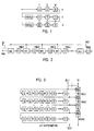
- FIG. 2 shows the structure of a horizontal portion of a filter according to the invention.
- This horizontal portion comprises operator elements, the number of which is W and each of which consists of one comparing means min and one delay means D, the operator elements being connected one after another in such a way that the output of the delay means D of a preceding operator element is connected to the first input of the comparing means min of the following operator element.
- the input IH of the horizontal portion is connected to the first input of the comparing means min of the first operator element and also to the second input of the comparing means min of each operator element.
- each operator element receives simultaneously the value coming to its input IH and the result of the operation (for instance minimum) of the preceding operator element delayed in each operator element approximately by the delay of the delay means D, i.e.
- the output of the horizontal portion of Figure 2 is formed by the output MINW of the Wth operator element. This represents the minimum or maximum values searched for in the portions including W successive samples, which portions have been allowed to slide over the one after another organized horizontal lines of the basic data matrix.
- FIG 3 shows the structure of a vertical portion of a filter according to the invention.
- This vertical portion comprises operator elements, the number of which is H and which are similar to those in Figure 2, the operator elements being connected one after another in such a way that the output of the delay means D of a preceding operator element is connected to the first input of the comparing means of the following operator element.
- the output of the Hth operator element forms the output MINH of the vertical portion.
- the vertical portion further comprises delay lines, the number of which is H and each of which comprises x+1 delay means D connected one after another, the input IV of the vertical portion being connected both to the first and the second input of the comparing means min of the first operator element and also to the input of the first delay line.
- each delay line is connected both to the second input of the comparing means min of the following operator element and to the input of the following delay line.
- the erosion or dilation process can be applied to sets including H sample values below each other of the vertical rows of the basic data matrix or to find the minimum or maximum value of each of the sets.
- a very substantial property of the filter according to the invention is the possibility of connecting horizontal and vertical portions forming the filter one after another in a desired manner.
- the most conventional way is to connect one horizontal portion and one vertical portion to each other, whereby the filter processes a segment of a basic data matrix.
- a filter suited for processing a rectangular segment is realized as a concrete component, such as an integrated circuit, the problem easily emerges that the sphere of influence of the circuit, i.e. the dimensions of the segments thereof are not sufficient for the application planned.
- the filter of the invention can be extended very easily by connecting filter structures capable of processing a certain segment one after another in such a way that the horizontal portions thereof and the vertical portions, respectively, are connected one after another, which provides a filter structure the dimensions of the processing neighbourhood of which are equal to the sum of the dimensions of the parts thereof.
- a filter is provided the dimensions of the processing neighbourhood of which are 2Wx2H.
- the circuit of Figure 2 shows beside its input IH another input MIN and beside its output another output IHO.
- the horizontal portion of the second filter By connecting the horizontal portion of the second filter after the horizontal portion of the first filter, the horizontal portion can be extended to continue quite like the chain shown in Figure 2, whereby its length increases in the proportion with the number of operator elements of this increased horizontal portion.
- filters according to the invention can be connected one after another also in many other ways, e.g. in such a way that an operation of erosion is at first applied to the basic data by means of a filter according to the invention, and immediately after that, an operation of dilation by means of a similar filter, but now naturally arranged to search for maximums. Consequently, arbitrary numbers of filters according to the invention, both dilation and erosion filters, can be connected one after another in an arbitrary manner without disturbing the function of the filters. In this way, images filtered in different ways can be produced for instance in image processing, which images, say subtracted from each other, bring forward the very property searched for with special emphasis.
- a division of the operators into separate horizontal and vertical portions in the local neighbourhood W*H decreases the number of necessary maximum/minimum operators (dilation/erosion operators) from W*H to W+H compared with the traditional structure of realization.
- the operating and realizing principle of the filter according to the invention makes a flexible modular extension from the neighbourhood 1*1 till the neighbourhood W*H possible, in which W and H are optional positive integers.
- a restriction is caused only by the dimensions of the basic data to be processed, so that W ⁇ x and H ⁇ y.
- the neighbourhood W*H can easily be configurated to neighbourhood W1*H1, in which 1 ⁇ W1 ⁇ W and 1 ⁇ H1 ⁇ H. This property makes a versatile effective image segmentation for instance in image processing possible.
- An advantage of the filter is its capability of eliminating unnecessary data samples whenever it is observed that they cannot be maximums (dilation) or minimums (erosion) of the neighbourhood W*H, which decreases the amount of the data to be processed. Due to this, the method is very quick, the delay is defined only by the time required for one maximum/minimum operation. The operations can be performed in real time. If, for instance, a line camera is used for producing an image, no separate extensive image memory is needed for storing the data to be processed.
- the filter suits especially well for image processing (pattern recognition, image segmentation) and decreases remarkably the realization costs compared with conventional solutions.
Landscapes
- General Physics & Mathematics (AREA)
- Engineering & Computer Science (AREA)
- Theoretical Computer Science (AREA)
- Physics & Mathematics (AREA)
- Image Analysis (AREA)
- Image Processing (AREA)
- Closed-Circuit Television Systems (AREA)
- Apparatus For Radiation Diagnosis (AREA)
- Prostheses (AREA)
- Centrifugal Separators (AREA)
- Networks Using Active Elements (AREA)
- Filtering Of Dispersed Particles In Gases (AREA)
- Collating Specific Patterns (AREA)
- Glass Compositions (AREA)
- Developing Agents For Electrophotography (AREA)
Abstract
Description
- The present invention relates to a filter for applying dilation and/or erosion operations of mathematical morphology using a W x H rectangular structuring element to a two-dimensional matrix of discrete values, the width of the matrix being x and the height being y,
the filter comprising a horizontal portion for applying said dilation or erosion operation to a W x 1 local neighbourhood and a vertical portion for applying said dilation or erosion operation to a 1 x H local neighbourhood,
whereby the portions are connected one after the other and the matrix elements are applied serially to the first portion, the output of one portion being connected to the input of the other portion,
said portions comprising a multiplicity of delay means, each providing an equal delay, and a multiplicity of comparing means for comparing two input values and producing the lesser or greater of theses values at their output, in the cases of erosion and dilation respectively,
wherein each portion comprises a set of identical operator elements connected one after another, the horizontal portion comprising W such operator elements, and the vertical portion comprising H such operator elements. - Mathematical morphology is a formal method of shape representation and analysis. Basic operations thereof are erosion and dilation, by chaining of which in a suitable manner it is possible to provide e.g. effective and usable image processing methods. For instance, many applications of computer vision, such as pattern recognition, are based on the use of morphological operators.
- In mathematical morphology, the basic operations process the image by means of so-called structuring elements. A structuring element is a neighbourhood in which an operator is effective. In gray-scale morphology, dilation stands for the maximum of the local neighbourhood defined by the structuring element and erosion stands for the minimum, respectively.
- Basic data to be processed has been arranged in the form of a matrix, in which each line comprises x samples and the total number of lines is y. In the following example, the dilation and erosion operations for basic data of the size of x=6 and y=6 are examined. The local neighbourhood is rectangular with the dimensions W=3 and H=3, where W is a horizontal and H a vertical dimension.

- Traditionally, operators are realized by means of the structure of Figure 1. It comprises delay means D connected one after another to form horizontal lines, each line comprising W delay means, which lines, H in number, are chained one after another in such a way that between each horizontal line is connected a delay line, the length of which is (X-W) times the delay of one delay means D. In this structure, a processing means has to be connected to each delay means D of each horizontal line, whereby the processing means has to compare WxH values with each other to find the minimum/maximum value desired. Thus the processing means will be quite complicated and therefore also slow. An image processing unit realized in this manner in principle is disclosed e.g. by U.S. Patent Specification 4 692 943.
- A filter defined in the opening paragraph can be formed on the basis of information given in NONLINEAR IMAGE PROCESSING, vol. 1247, 15 Feb 1990, Santa Clara, California, pages 145-156; A.C.P.LOUI et al.: "High-speed architectures for morphological image processing". This reference shows a serial combination of a number of identical elements to form dilation and/or erosion processors and gives the teaching that a two-dimensional dilation/erosion operation can be accomplished by coupling serially a horizontal and a vertical portion. The elements used for the dilation and/or erosion processors include, however, several components and the serial combinations formed thereby are slow in operation.
- To solve the problems attached to the prior art filter structures and caused especially by difficulty of extension, complexity of structure and consequent slow operation, the filter of the invention is characterized by each of said operator elements consisting of one said comparing means and one said delay means, the output of said comparing means being connected to the input of said delay means, the output of the delay means of a preceding operator element being connected to the first input of the comparing means of the following operator element,
the input of the horizontal portion being connected to the first input of the comparing means of the first operator element and also to the second input of the comparing means of each operator element in the said horizontal portion, the output of the Wth operator element forming the output of said horizontal portion,
the said vertical portion further comprising H delay lines each comprising x+1 further delay means connected one after another, the input of said vertical portion being connected to both first and second inputs of the comparing means of the first operator element of said vertical portion and also to the input of the first of said delay lines, the output of each delay line being connected both to the second input of the comparing means of the following operator element and to the input of the following delay line, and the output of the Hth operator element forming the output of said vertical portion. - In this filter structure of the invention, basic data x*y is processed by a dilation or erosion operation in a local neighbourhood W*H, which is made to slide over the basic data x*y. According to the method, the operations of dilation and erosion are performed in such a way that the maximum (dilation) or the minimum (erosion) is at first searched for in a local neighbourhood W*1 (horizontal portion). In the result obtained in this way, the maximum (dilation) or the minimum (erosion) is then searched for in a
local neighbourhood 1*H (vertical portion). The performing order of the horizontal and vertical por tions can also be reverse. - To visualize the function of the filter, the function of a horizontal operator performing the minimum operation (erosion) is examined as an example. The function is described in table 2. The uppermost horizontal line presents an incoming data stream delayed by one clock period (=MIN1), which stream the minimum is searched for a neighbourhood 5*1 in this case. Each line represents the minimum value of a certain neighbourhood, which value can be calculated in the manner presented in the table. The arrows show from which values the minimum value is generated each time. The columns again show the situation at a certain moment. The table presents the operations required for the calculation of three successive minimum values.

- In the method, the minimum is searched for in successive samples n, n+1, n+2, n+3,..., n+(W-1).
- Sample n (=minimum in
neighbourhood 1*1 = MIN1 = MIN{n}) is received by the input of the horizontal portion at a moment t, sample n+1 at a moment t+1 etc. During t+1 the minimum is calculated from the samples n and n+1 and the result is the minimum inneighbourhood 2*1, i.e. MIN2 (=min{MIN1,n+1} = min{n,n+1}). During t+2 the minimum is calculated from the samples n+2 and MIN2 and the result is the minimum in neighbourhood 3*1, i.e. MIN3 (=min{MIN2,n+2} = min{n,n+1,n+2}). Correspondingly, during t+3 the minimum is calculated from the samples n+3 and MIN3 and the result is the minimum in neighbourhood 4*1, i.e. MIN4 (=min{MIN3, n+3}= min{n,n+1,n+2,n+3}). By continued analysis the minimum is reached in dimension W*1, where W is the horizontal dimension of the neighbourhood (W=5 in the example above). - Because at the moment t0 the minimum operations
MIN1(t0) = min{n+t0}
MIN2(t0) = min{MIN1(t0-1),n+t0}
MIN3(t0) = min{MIN2(t0-1),n+t0}
MIN4(t0) = min{MIN3(t0-1),n+t0}
...
MINW(t0) = min{MIN(W-1)(t0-1),n+t0}
can be performed in parallel (n+t0 = sample at the moment t0), the operations can be performed by means of the horizontal portion, comprising W operator elements connected one after another, each of which operator elements consists of one comparing means and one delay means, the output of the delay means of a preceding operator element being connected to the first input of the comparing means of the following operator element and the input of the horizontal portion being connected to the first input of the comparing means of the first operator element and also to the second input of the comparing means of each operator element, whereby the output of the Wth operator element forms the output of the horizontal portion. The operations can thus be performed in real time in such a way that the minimum in the local neighbourhood W*1 is obtained at the end of the chain in each clock period. Operations to be performed at the moment t0 are described in table 3.
- On the other hand, the vertical operation can be performed by means of the vertical portion, comprising H operator elements connected one after another, the output of the delay means of a preceding operator element being connected to the first input of the comparing means of the following operator element, whereby the output of the Hth operator element forms the output of the vertical portion, and H delay lines with x+1 delay means connected one after another, the input of the vertical portion being connected both to the first and the second input of the comparing means of the first operator element and also to the input of the first delay line and the output of each delay line being connected both to the second input of the comparing means of the following operator element and to the input of the following delay line.
- The function of the vertical portion is visualized in table 4. The uppermost horizontal line shows the incoming data stream (from the horizontal portion) delayed by one clock period (=MIN1). In this table, the minimum (erosion) in
neighbourhood 1*5 is searched for. Each line presents the minimum in a certain neighbourhood, which can be calculated in the manner shown in the table. The arrows show the route of the data stream leading to the calculation of thefirst neighbourhood 1*5.
- In the method, the minimum is searched for in the samples n, n+x, n+2x, n+3x,..., n+(H-1)x to be obtained from the horizontal portion, where H is the vertical dimension of the neighbourhood (H=5 in example above) and x is the line length of the data to be processed.
- Sample n is received by the input of the vertical portion (= minimum in
neighbourhood 1*1 = MIN1 = min{n}) at the moment t, sample n+x at the moment t+1 etc. During t+1 the minimum is calculated from the samples n and n+x and the result is the minimum inneighbourhood 1*2, i.e. MIN2 (= min{MIN1,n+x} = min{n,n+x}). During t+2 the minimum is calculated from the samples n+2x and MIN2 and the result is the minimum inneighbourhood 1*3, i.e. MIN3 (= min{MIN2, n+2x} = min{n,n+x,n+2x}). By continued analysis the minimum is reached inneighbourhood 1*H. - Because at the moment t0 the minimum operations
MIN1(t0) = min{n+t0}
MIN2(t0) = min{MIN1(t0-1),n+t0+x-1}
MIN3(t0) = min{MIN2(t0-1),n+t0+2(x-1)}
MIN4(t0) = min{MIN3(t0-1),n+t0+3(x-1)}
...
MINH(t0) = min{MINH-1(t0-1),n+t0+(H-1)(x-1)}
can be performed in parallel (n+t0 = sample at the moment t0), the operations can be performed in real time. The minimum in thelocal neighbourhood 1*H is obtained at the end of the chain in each clock period. Operations to be performed at the moment t0 are described in table 5.
- The horizontal and vertical portions based on the minimum operation have been discussed above, which portions perform together the operation of erosion of mathematical morphology in neighbourhood W*H. A maximum operator performing dilation can also be subjected to a similar examination.
- Dilation and erosion can both be performed with the same structure. The operation is reversed by changing the basic operators searching for the minimum for those searching for the maximum or vice versa.
- A filter according to the invention is described below in more detail with reference to the enclosed drawing, in which
- Figure 1 shows the structure of a prior art filter,
- Figure 2 shows the structure of a horizontal portion of a filter according to the invention, and
- Figure 3 shows the structure of a vertical portion of the filter according to the invention.
- Figure 2 shows the structure of a horizontal portion of a filter according to the invention. This horizontal portion comprises operator elements, the number of which is W and each of which consists of one comparing means min and one delay means D, the operator elements being connected one after another in such a way that the output of the delay means D of a preceding operator element is connected to the first input of the comparing means min of the following operator element. The input IH of the horizontal portion is connected to the first input of the comparing means min of the first operator element and also to the second input of the comparing means min of each operator element. Thus each operator element receives simultaneously the value coming to its input IH and the result of the operation (for instance minimum) of the preceding operator element delayed in each operator element approximately by the delay of the delay means D, i.e. in practice most usually by one clock period. The output of the horizontal portion of Figure 2 is formed by the output MINW of the Wth operator element. This represents the minimum or maximum values searched for in the portions including W successive samples, which portions have been allowed to slide over the one after another organized horizontal lines of the basic data matrix.
- Figure 3 shows the structure of a vertical portion of a filter according to the invention. This vertical portion comprises operator elements, the number of which is H and which are similar to those in Figure 2, the operator elements being connected one after another in such a way that the output of the delay means D of a preceding operator element is connected to the first input of the comparing means of the following operator element. The output of the Hth operator element forms the output MINH of the vertical portion. The vertical portion further comprises delay lines, the number of which is H and each of which comprises x+1 delay means D connected one after another, the input IV of the vertical portion being connected both to the first and the second input of the comparing means min of the first operator element and also to the input of the first delay line. On the other hand, the output of each delay line is connected both to the second input of the comparing means min of the following operator element and to the input of the following delay line. By means of this vertical portion, the erosion or dilation process can be applied to sets including H sample values below each other of the vertical rows of the basic data matrix or to find the minimum or maximum value of each of the sets.
- A very substantial property of the filter according to the invention is the possibility of connecting horizontal and vertical portions forming the filter one after another in a desired manner. The most conventional way is to connect one horizontal portion and one vertical portion to each other, whereby the filter processes a segment of a basic data matrix. When such a filter suited for processing a rectangular segment is realized as a concrete component, such as an integrated circuit, the problem easily emerges that the sphere of influence of the circuit, i.e. the dimensions of the segments thereof are not sufficient for the application planned. As to these dimensions,however, the filter of the invention can be extended very easily by connecting filter structures capable of processing a certain segment one after another in such a way that the horizontal portions thereof and the vertical portions, respectively, are connected one after another, which provides a filter structure the dimensions of the processing neighbourhood of which are equal to the sum of the dimensions of the parts thereof. For instance, when two filters capable of processing a WxH segment are connected one after another in this way, a filter is provided the dimensions of the processing neighbourhood of which are 2Wx2H. To make a connection like this possible, the circuit of Figure 2 shows beside its input IH another input MIN and beside its output another output IHO. To make such a chaining of horizontal portions possible, it is also necessary to break off the connection between the input IH of the horizontal portion and the first input of the comparing means of the first operator element, which now gets its own input MIN. On the other hand, the other output IHO relates to the line through which the other inputs of all operator elements are supplied with respective initial value. By connecting the horizontal portion of the second filter after the horizontal portion of the first filter, the horizontal portion can be extended to continue quite like the chain shown in Figure 2, whereby its length increases in the proportion with the number of operator elements of this increased horizontal portion.
- A similar chaining can be realized also with the vertical portions shown in Figure 3. Then the output MINH of a preceding vertical portion is connected to the input IV of the following vertical portion, and on the other hand, the output DLO of the last delay line is connected to the input DLI of the delay line of the vertical portion of the following filter. This input DLI thus connected to the input of the first delay line of the vertical portion is then naturally disconnected from the first input IV of the first operator element of the vertical portion in question.
- Further, it shall be noted that filters according to the invention can be connected one after another also in many other ways, e.g. in such a way that an operation of erosion is at first applied to the basic data by means of a filter according to the invention, and immediately after that, an operation of dilation by means of a similar filter, but now naturally arranged to search for maximums. Consequently, arbitrary numbers of filters according to the invention, both dilation and erosion filters, can be connected one after another in an arbitrary manner without disturbing the function of the filters. In this way, images filtered in different ways can be produced for instance in image processing, which images, say subtracted from each other, bring forward the very property searched for with special emphasis.
- In the filter according to the invention, a division of the operators into separate horizontal and vertical portions in the local neighbourhood W*H decreases the number of necessary maximum/minimum operators (dilation/erosion operators) from W*H to W+H compared with the traditional structure of realization.
- Further, a division of the operators into horizontal and vertical portions decreases the extent of wiring required for the realization of electronics or IC in the proportion (W+H)/(W*H) compared with the traditional solution.
- The operating and realizing principle of the filter according to the invention makes a flexible modular extension from the
neighbourhood 1*1 till the neighbourhood W*H possible, in which W and H are optional positive integers. A restriction is caused only by the dimensions of the basic data to be processed, so that W≦x and H≦y. - The neighbourhood W*H can easily be configurated to neighbourhood W₁*H₁, in which 1≦W₁≦W and 1≦H₁≦H. This property makes a versatile effective image segmentation for instance in image processing possible.
- An advantage of the filter is its capability of eliminating unnecessary data samples whenever it is observed that they cannot be maximums (dilation) or minimums (erosion) of the neighbourhood W*H, which decreases the amount of the data to be processed. Due to this, the method is very quick, the delay is defined only by the time required for one maximum/minimum operation. The operations can be performed in real time. If, for instance, a line camera is used for producing an image, no separate extensive image memory is needed for storing the data to be processed. The filter suits especially well for image processing (pattern recognition, image segmentation) and decreases remarkably the realization costs compared with conventional solutions.
- The filter of the invention has above been described by means of one exemplifying structure only and it is understandable that it could be changed to some extent without differing from the scope of protection defined by the enclosed claims, however.
Claims (1)
- A filter for applying a dilation or an erosion operation of mathematical morphology using a W x H rectangular structuring element to a two-dimensional matrix of discrete values, the width of the matrix being x and the height being y,
the filter comprising a horizontal portion for applying said dilation or erosion operation to a W x 1 local neighbourhood and a vertical portion for applying said dilation or erosion operation to a 1 x H local neighbourhood,
whereby the portions are connected one after the other and the matrix elements are applied serially to the first portion, the output (MINW) of one portion being connected to the input (IV) of the other portion,
said portions comprising a multiplicity of delay means (D), each providing an equal delay, and a multiplicity of comparing means (min) for comparing two input values and producing the lesser or greater of these values at their output, in the cases of erosion and dilation respectively,
wherein each portion comprises a set of identical operator elements connected one after another, the horizontal portion comprising W such operator elements, and the vertical portion comprising H such operator elements,
characterised by
each of said operator elements consisting of one said comparing means (min) and one said delay means (D), the output of said comparing means (min) being connected to the input of said delay means (D), the output of the delay means (D) of a preceding operator element being connected to the first input of the comparing means (min) of the following operator element,
the input (IH) of the horizontal portion being connected to the first input of the comparing means (min) of the first operator element and also to the second input of the comparing means (min) of each operator element in the said horizontal portion, the output (MINW) of the Wth operator element forming the output of said horizontal portion,
the said vertical portion further comprising H delay lines each comprising x+1 further delay means (D) connected one after another, the input (IV) of said vertical portion being connected to both first and second inputs of the comparing means (min) of the first operator element of said vertical portion and also to the input of the first of said delay lines, the output of each delay line being connected both to the second input of the comparing means (min) of the following operator element and to the input of the following delay line, and the output of the Hth operator element forming the output of said vertical portion.
Applications Claiming Priority (3)
| Application Number | Priority Date | Filing Date | Title |
|---|---|---|---|
| FI912343A FI90150C (en) | 1991-05-14 | 1991-05-14 | Filter |
| FI912343 | 1991-05-14 | ||
| PCT/FI1992/000147 WO1992021093A1 (en) | 1991-05-14 | 1992-05-08 | Filter for dilation and erosion of images |
Publications (2)
| Publication Number | Publication Date |
|---|---|
| EP0586420A1 EP0586420A1 (en) | 1994-03-16 |
| EP0586420B1 true EP0586420B1 (en) | 1995-08-09 |
Family
ID=8532521
Family Applications (1)
| Application Number | Title | Priority Date | Filing Date |
|---|---|---|---|
| EP92909928A Expired - Lifetime EP0586420B1 (en) | 1991-05-14 | 1992-05-08 | Filter for dilation and erosion of images |
Country Status (8)
| Country | Link |
|---|---|
| US (1) | US5436984A (en) |
| EP (1) | EP0586420B1 (en) |
| JP (1) | JPH06508703A (en) |
| AT (1) | ATE126374T1 (en) |
| AU (1) | AU1685192A (en) |
| DE (1) | DE69204064T2 (en) |
| FI (1) | FI90150C (en) |
| WO (1) | WO1992021093A1 (en) |
Families Citing this family (9)
| Publication number | Priority date | Publication date | Assignee | Title |
|---|---|---|---|---|
| FR2712415B1 (en) * | 1993-11-09 | 1995-12-22 | Ge Medical Syst Sa | Method for automatically locating points of interest during a stereotaxic examination in mammography. |
| KR100304660B1 (en) * | 1995-09-22 | 2001-11-22 | 윤종용 | Video signal encoding method and encoder through cumulative error processing |
| US5817133A (en) * | 1997-03-04 | 1998-10-06 | Medtronic, Inc. | Pacemaker with morphological filtering of sensed cardiac signals |
| US6128414A (en) * | 1997-09-29 | 2000-10-03 | Intermec Ip Corporation | Non-linear image processing and automatic discriminating method and apparatus for images such as images of machine-readable symbols |
| EP1360833A1 (en) | 2000-08-31 | 2003-11-12 | Rytec Corporation | Sensor and imaging system |
| WO2004023787A2 (en) | 2002-09-06 | 2004-03-18 | Rytec Corporation | Signal intensity range transformation apparatus and method |
| WO2006123422A1 (en) * | 2005-05-20 | 2006-11-23 | Mitsubishi Denki Kabushiki Kaisha | Image processing device and image processing program |
| EP2848000B1 (en) | 2012-05-11 | 2018-09-19 | Intel Corporation | Systems and methods for row causal scan-order optimization stereo matching |
| US10846852B2 (en) * | 2016-12-23 | 2020-11-24 | Bio-Rad Laboratories, Inc. | Reduction of background signal in blot images |
Family Cites Families (7)
| Publication number | Priority date | Publication date | Assignee | Title |
|---|---|---|---|---|
| US4665554A (en) * | 1983-07-13 | 1987-05-12 | Machine Vision International Corporation | Apparatus and method for implementing dilation and erosion transformations in digital image processing |
| DE3347645C1 (en) * | 1983-12-30 | 1985-10-10 | Dr.-Ing. Ludwig Pietzsch Gmbh & Co, 7505 Ettlingen | Method and device for opto-electronic testing of a surface pattern on an object |
| US4641356A (en) * | 1984-08-24 | 1987-02-03 | Machine Vision International Corporation | Apparatus and method for implementing dilation and erosion transformations in grayscale image processing |
| FR2586120B1 (en) * | 1985-08-07 | 1987-12-04 | Armines | METHOD AND DEVICE FOR SEQUENTIAL IMAGE TRANSFORMATION |
| US4724543A (en) * | 1985-09-10 | 1988-02-09 | Beckman Research Institute, City Of Hope | Method and apparatus for automatic digital image analysis |
| US4760607A (en) * | 1986-07-31 | 1988-07-26 | Machine Vision International Corporation | Apparatus and method for implementing transformations in grayscale image processing |
| JPS63104185A (en) * | 1986-10-22 | 1988-05-09 | Seiko Instr & Electronics Ltd | Circuit for enlarging and reducing conversion of picture |
-
1991
- 1991-05-14 FI FI912343A patent/FI90150C/en active IP Right Grant
-
1992
- 1992-05-08 WO PCT/FI1992/000147 patent/WO1992021093A1/en not_active Ceased
- 1992-05-08 JP JP4508994A patent/JPH06508703A/en active Pending
- 1992-05-08 US US08/137,158 patent/US5436984A/en not_active Expired - Fee Related
- 1992-05-08 DE DE69204064T patent/DE69204064T2/en not_active Expired - Fee Related
- 1992-05-08 EP EP92909928A patent/EP0586420B1/en not_active Expired - Lifetime
- 1992-05-08 AU AU16851/92A patent/AU1685192A/en not_active Abandoned
- 1992-05-08 AT AT92909928T patent/ATE126374T1/en not_active IP Right Cessation
Also Published As
| Publication number | Publication date |
|---|---|
| ATE126374T1 (en) | 1995-08-15 |
| FI912343A0 (en) | 1991-05-14 |
| DE69204064D1 (en) | 1995-09-14 |
| AU1685192A (en) | 1992-12-30 |
| FI90150B (en) | 1993-09-15 |
| US5436984A (en) | 1995-07-25 |
| EP0586420A1 (en) | 1994-03-16 |
| JPH06508703A (en) | 1994-09-29 |
| FI90150C (en) | 1993-12-27 |
| WO1992021093A1 (en) | 1992-11-26 |
| FI912343L (en) | 1992-11-15 |
| DE69204064T2 (en) | 1996-01-04 |
Similar Documents
| Publication | Publication Date | Title |
|---|---|---|
| Starck et al. | Image restoration with noise suppression using the wavelet transform | |
| US6130967A (en) | Method and apparatus for a reduced instruction set architecture for multidimensional image processing | |
| CA2130336A1 (en) | Method and apparatus for rapidly processing data sequences | |
| US5436984A (en) | Minimum delay dilation/erosion filter | |
| US4802108A (en) | Circuit for providing a select rank-order number from a plurality of numbers | |
| EP0350121A1 (en) | Integrated circuit and picture-processing device | |
| CN114418064A (en) | Target detection method, terminal equipment and storage medium | |
| WO1997005564A1 (en) | Apparatus for high speed morphological processing | |
| DE69423073T2 (en) | Circuit and method for shifting and rounding | |
| EP0684577B1 (en) | Binary digital image feature extracting process | |
| Aizenberg et al. | Extraction and localization of important features an gray-scale images: Implementation on the CNN | |
| Delman | Digital pipelined hardware median filter design for real-time image processing | |
| JPH0320880A (en) | Conversion circuit | |
| Storey et al. | An adaptive pipeline processor for real-time image processing | |
| CN116865721A (en) | Filter circuits, chips and electronic equipment | |
| JP3219915B2 (en) | Image compression circuit | |
| JPH02188879A (en) | Picture processor | |
| EP0825523A1 (en) | Method and circuit for multiplying a multiplicand and a multiplier by the Booth-method in iterative steps | |
| Fischl et al. | Fast adaptive alternatives to nonlinear diffusion in image enhancement: Green's function approximators and nonlocal filters | |
| JPH0126115B2 (en) | ||
| Polgember et al. | Simplification of sequences of operators | |
| GB2171574A (en) | Image contraction and dilation | |
| JPS61184967A (en) | Image processor | |
| Wambacq et al. | Fast adaptive filtering with special hardware | |
| JPH0361881A (en) | Target detection circuit |
Legal Events
| Date | Code | Title | Description |
|---|---|---|---|
| PUAI | Public reference made under article 153(3) epc to a published international application that has entered the european phase |
Free format text: ORIGINAL CODE: 0009012 |
|
| 17P | Request for examination filed |
Effective date: 19931104 |
|
| AK | Designated contracting states |
Kind code of ref document: A1 Designated state(s): AT BE CH DE DK ES FR GB GR IT LI LU MC NL SE |
|
| 17Q | First examination report despatched |
Effective date: 19940627 |
|
| GRAA | (expected) grant |
Free format text: ORIGINAL CODE: 0009210 |
|
| AK | Designated contracting states |
Kind code of ref document: B1 Designated state(s): AT BE CH DE DK ES FR GB GR IT LI LU MC NL SE |
|
| PG25 | Lapsed in a contracting state [announced via postgrant information from national office to epo] |
Ref country code: NL Free format text: LAPSE BECAUSE OF FAILURE TO SUBMIT A TRANSLATION OF THE DESCRIPTION OR TO PAY THE FEE WITHIN THE PRESCRIBED TIME-LIMIT Effective date: 19950809 Ref country code: MC Free format text: LAPSE BECAUSE OF NON-PAYMENT OF DUE FEES Effective date: 19950809 Ref country code: LI Effective date: 19950809 Ref country code: IT Free format text: LAPSE BECAUSE OF FAILURE TO SUBMIT A TRANSLATION OF THE DESCRIPTION OR TO PAY THE FEE WITHIN THE PRE;WARNING: LAPSES OF ITALIAN PATENTS WITH EFFECTIVE DATE BEFORE 2007 MAY HAVE OCCURRED AT ANY TIME BEFORE 2007. THE CORRECT EFFECTIVE DATE MAY BE DIFFERENT FROM THE ONE RECORDED.SCRIBED TIME-LIMIT Effective date: 19950809 Ref country code: GR Free format text: LAPSE BECAUSE OF FAILURE TO SUBMIT A TRANSLATION OF THE DESCRIPTION OR TO PAY THE FEE WITHIN THE PRESCRIBED TIME-LIMIT Effective date: 19950809 Ref country code: ES Free format text: THE PATENT HAS BEEN ANNULLED BY A DECISION OF A NATIONAL AUTHORITY Effective date: 19950809 Ref country code: DK Effective date: 19950809 Ref country code: CH Effective date: 19950809 Ref country code: BE Effective date: 19950809 Ref country code: AT Effective date: 19950809 |
|
| REF | Corresponds to: |
Ref document number: 126374 Country of ref document: AT Date of ref document: 19950815 Kind code of ref document: T |
|
| REF | Corresponds to: |
Ref document number: 69204064 Country of ref document: DE Date of ref document: 19950914 |
|
| PG25 | Lapsed in a contracting state [announced via postgrant information from national office to epo] |
Ref country code: SE Effective date: 19951109 |
|
| ET | Fr: translation filed | ||
| NLV1 | Nl: lapsed or annulled due to failure to fulfill the requirements of art. 29p and 29m of the patents act | ||
| PG25 | Lapsed in a contracting state [announced via postgrant information from national office to epo] |
Ref country code: LU Free format text: LAPSE BECAUSE OF NON-PAYMENT OF DUE FEES Effective date: 19960531 |
|
| PLBE | No opposition filed within time limit |
Free format text: ORIGINAL CODE: 0009261 |
|
| 26N | No opposition filed | ||
| PGFP | Annual fee paid to national office [announced via postgrant information from national office to epo] |
Ref country code: FR Payment date: 19970529 Year of fee payment: 6 |
|
| PGFP | Annual fee paid to national office [announced via postgrant information from national office to epo] |
Ref country code: DE Payment date: 19970627 Year of fee payment: 6 |
|
| PG25 | Lapsed in a contracting state [announced via postgrant information from national office to epo] |
Ref country code: FR Free format text: LAPSE BECAUSE OF NON-PAYMENT OF DUE FEES Effective date: 19980531 |
|
| PG25 | Lapsed in a contracting state [announced via postgrant information from national office to epo] |
Ref country code: DE Free format text: LAPSE BECAUSE OF NON-PAYMENT OF DUE FEES Effective date: 19990302 |
|
| REG | Reference to a national code |
Ref country code: FR Ref legal event code: ST |
|
| PGFP | Annual fee paid to national office [announced via postgrant information from national office to epo] |
Ref country code: GB Payment date: 20010424 Year of fee payment: 10 |
|
| REG | Reference to a national code |
Ref country code: GB Ref legal event code: IF02 |
|
| PG25 | Lapsed in a contracting state [announced via postgrant information from national office to epo] |
Ref country code: GB Free format text: LAPSE BECAUSE OF NON-PAYMENT OF DUE FEES Effective date: 20020508 |
|
| GBPC | Gb: european patent ceased through non-payment of renewal fee |
Effective date: 20020508 |