EP0586150B1 - Improved instrumentation probe - Google Patents
Improved instrumentation probe Download PDFInfo
- Publication number
- EP0586150B1 EP0586150B1 EP93306594A EP93306594A EP0586150B1 EP 0586150 B1 EP0586150 B1 EP 0586150B1 EP 93306594 A EP93306594 A EP 93306594A EP 93306594 A EP93306594 A EP 93306594A EP 0586150 B1 EP0586150 B1 EP 0586150B1
- Authority
- EP
- European Patent Office
- Prior art keywords
- outer casing
- tubular housing
- probe
- process stream
- trailing edge
- Prior art date
- Legal status (The legal status is an assumption and is not a legal conclusion. Google has not performed a legal analysis and makes no representation as to the accuracy of the status listed.)
- Expired - Lifetime
Links
Images

Classifications
-
- G—PHYSICS
- G01—MEASURING; TESTING
- G01K—MEASURING TEMPERATURE; MEASURING QUANTITY OF HEAT; THERMALLY-SENSITIVE ELEMENTS NOT OTHERWISE PROVIDED FOR
- G01K13/00—Thermometers specially adapted for specific purposes
- G01K13/02—Thermometers specially adapted for specific purposes for measuring temperature of moving fluids or granular materials capable of flow
Definitions
- the present invention relates to instrumentation probes for use in erosive process streams and especially for sensing temperature in erosive process streams.
- Typical instrumentation probes consist of a generally tubular housing which projects into a process stream for sensing conditions in the process stream.
- thermometer design for use with jet engine hot gases is described in GB-A-610317.
- One embodiment comprises a generally air-foil body having inlet apertures on its leading edge to cause hot gases to stream into the body and around a temperature sensor located in close proximity to the inlet apertures. After flowing round the sensor the hot gases pass along the interior of the body and exit through outlet apertures at the trailing edge thereof.
- an instrument probe for use in erosive process streams comprises: an outer casing having a bore therethrough transverse to its longitudinal axis; and a tubular housing, adapted to receive and enclose a sensing element, located in the bore and secured therein by welded plug means, whereby that portion of the tubular housing which, in use of the probe, would otherwise be in contact with a process stream is totally enclosed by the outer casing and plug means; and wherein the outer casing of the probe has a substantially air-foil shape with (i) a leading curved edge that is at a distance from the axis of the tubular housing in the range of from 2 to 4 times the radius thereof, and (ii) a trailing edge that is at a distance from the axis of the tubular housing in the range of from 2 to 2.5 times the radius thereof, but not more than distance (i); whereby, in use, the outer casing is substantially non-disruptive of the process stream flow.
- the invention provides a conduit or container for the passage of an erosive process stream, in combination with the afore-defined instrument probe located therein with the said outer casing of the probe aligned to have its leading edge substantially directed towards the direction from which the process stream will flow in use, and its trailing edge substantially directed towards the direction to which the process stream will flow in use after passing the location of the trailing edge.
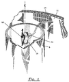
- Figure 1 is a schematic fragmentary illustration of an improved instrument probe of the present invention installed in a riser conduit positioned in a vessel through which conduit an erosive process stream is passed.
- Figure 2 is a side elevation of the outer casing of an instrument probe of the present invention, showing a particularly preferred aerodynamic design of the casing.
- Figure 3 is a cross-sectional view taken along lines A-A of Figure 2.
- FIG 1 is a schematic illustration of an instrument probe of the present invention having an aerodynamically shaped outer casing 10 located in a riser conduit 5 through which an erosive process fluid flows.
- the riser conduit 5 is positioned within a reactor vessel having a wall 11.
- process fluid flowing through the reactor is directed to flow around the outer casing 10 in a substantially aerodynamic fashion, so as to be substantially non-disruptive of the flow of fluid through the riser conduit 5, thereby preventing erosion of the housing within the casing 10 containing the sensor.
- the outer casing 10 of the instrument probe has a substantially air foil design and particularly the design shown in Figure 2.
- the instrument probe includes a tubular housing member 14 of sufficient length to extend from a point within the conduit 5 to a location external the conduit 5.
- the tubular housing 14 is preferably sufficiently long to extend to a location external the reactor vessel wall 11.
- the end of the tubular housing 14 that extends into the process stream to be sensed is surrounded by outer casing 10.
- the outer casing has a substantially aerodynamic shape, especially an outer shape 10 similar to an air foil.
- the outer casing 10 has three sections: a first section 16; a middle second section 17 and a third section 18.
- the outer casing 10 is a solid unit with a cylindrical tubular opening therein which is transverse to its longitudinal axis and has a diameter sufficient to be able to readily receive and remove tubular housing 14.
- the outer casing 10, preferably, is welded to the tubular housing 14 at the first end 15 of housing 14 by weld 27.
- the outer casing 10 optionally and preferably is also welded to the conduit 5 by welds 8.
- conduit 5 and the reactor vessel wall 11 are each provided with a refractory lining 6.
- the casing 10 of the probe has a first section 16 with a curved leading edge 26 and a third section 18 with a curved trailing edge 28.
- the first section 16 of the outer casing 10 is slightly longer in length than the third section 18 of the casing 10.
- the length from leading edge 26 to the center of the cylindrical opening in outer casing 10 is from 2 to 4 times the radius of the cylindrical opening; whereas, the length from the trailing edge 28 to the center of the cylindrical opening is about 2 to 2 1/2 times the radius of the cylindrical opening.
- a mounting plate 34 is provided to secure the tubular housing 14 to the conduit 5 and to effectively provide a gas seal between the interior and the exterior of conduit 5. Also as is shown, the mounting plate 34 is fastened to the wall of conduit 5 by means of welds and optionally and preferably the tubular housing 14 is welded to mounting plate 34.
- a sensing element such as a thermocouple 32 is located within a tubular housing 14, extending substantially inward toward weld 27, thereby providing the primary means for measuring temperature within the process stream.
- the second end 25 of the tubular housing 14 is provided with conventional means 36, such as a threaded end, for connection to external equipment and devices.
- the outer casing 10 can be separately fabricated and placed over conventional thermocouple probes in use by welding at points such as 27 and 8, shown in Figure 3.
- the outer casing 10 will be made from metals such as 316 stainless steel; however, optionally it may be also coated with erosion resistant coating such as carbides, borides and aluminides, alloys of iron, nickel, cobalt, especially wear resistant alloys of cobalt-chromium and tungsten, and ceramics such as magnesia-stabilized zirconia.
- erosion resistant coating such as carbides, borides and aluminides, alloys of iron, nickel, cobalt, especially wear resistant alloys of cobalt-chromium and tungsten, and ceramics such as magnesia-stabilized zirconia.
Landscapes
- Physics & Mathematics (AREA)
- General Physics & Mathematics (AREA)
- Measuring Temperature Or Quantity Of Heat (AREA)
- Monitoring And Testing Of Nuclear Reactors (AREA)
- Testing Resistance To Weather, Investigating Materials By Mechanical Methods (AREA)
Description
- The present invention relates to instrumentation probes for use in erosive process streams and especially for sensing temperature in erosive process streams.
- There are many industrial processes in which it is desirable to sense conditions existing in a process stream by means of a sensor mounted within an instrumentation probe. Typical instrumentation probes consist of a generally tubular housing which projects into a process stream for sensing conditions in the process stream.
- An early thermometer design for use with jet engine hot gases is described in GB-A-610317. One embodiment comprises a generally air-foil body having inlet apertures on its leading edge to cause hot gases to stream into the body and around a temperature sensor located in close proximity to the inlet apertures. After flowing round the sensor the hot gases pass along the interior of the body and exit through outlet apertures at the trailing edge thereof.
- In practice, process streams frequently contain erosive particles, as is the case, for example, in fluid catalytic cracking and similar processes. These erosive particles erode the probe over time, which is highly undesirable. Considerable effort, therefore, has been directed in the process industry toward developing erosion-resistant alloys and erosion-resistant coatings for instrumentation probes. Notwithstanding these activities, there still remains a need for improved erosion and corrosion resistant instrumentation probes.
- Therefore, it is an object of the present invention to provide improved instrumentation probes for use especially in erosive environments.
- It is another object of the present invention to provide improvements in instrumentation probes for retrofitting of existing sensor probes.
- According to the present invention, an instrument probe for use in erosive process streams comprises: an outer casing having a bore therethrough transverse to its longitudinal axis; and a tubular housing, adapted to receive and enclose a sensing element, located in the bore and secured therein by welded plug means, whereby that portion of the tubular housing which, in use of the probe, would otherwise be in contact with a process stream is totally enclosed by the outer casing and plug means;
and wherein the outer casing of the probe has a substantially air-foil shape with (i) a leading curved edge that is at a distance from the axis of the tubular housing in the range of from 2 to 4 times the radius thereof, and (ii) a trailing edge that is at a distance from the axis of the tubular housing in the range of from 2 to 2.5 times the radius thereof, but not more than distance (i); whereby, in use, the outer casing is substantially non-disruptive of the process stream flow. - In another aspect the invention provides a conduit or container for the passage of an erosive process stream, in combination with the afore-defined instrument probe located therein with the said outer casing of the probe aligned to have its leading edge substantially directed towards the direction from which the process stream will flow in use, and its trailing edge substantially directed towards the direction to which the process stream will flow in use after passing the location of the trailing edge.
- These and other embodiments of the present invention, as well as other objects and advantages thereof, will be apparent from the "Detailed Description" which follows, as is illustrated in the accompanying drawings.
- Figure 1 is a schematic fragmentary illustration of an improved instrument probe of the present invention installed in a riser conduit positioned in a vessel through which conduit an erosive process stream is passed.
- Figure 2 is a side elevation of the outer casing of an instrument probe of the present invention, showing a particularly preferred aerodynamic design of the casing.
- Figure 3 is a cross-sectional view taken along lines A-A of Figure 2.
- Figure 1 is a schematic illustration of an instrument probe of the present invention having an aerodynamically shaped
outer casing 10 located in ariser conduit 5 through which an erosive process fluid flows. In the embodiment shown in Figure 1, theriser conduit 5 is positioned within a reactor vessel having awall 11. - As can be seen by the arrows, process fluid flowing through the reactor is directed to flow around the
outer casing 10 in a substantially aerodynamic fashion, so as to be substantially non-disruptive of the flow of fluid through theriser conduit 5, thereby preventing erosion of the housing within thecasing 10 containing the sensor. - In a particularly preferred embodiment of the present invention, the
outer casing 10 of the instrument probe has a substantially air foil design and particularly the design shown in Figure 2. - As is shown in Figure 3, the instrument probe includes a
tubular housing member 14 of sufficient length to extend from a point within theconduit 5 to a location external theconduit 5. In this particular instance where the conduit containing the process stream is located within a vessel, thetubular housing 14 is preferably sufficiently long to extend to a location external thereactor vessel wall 11. As shown, the end of thetubular housing 14 that extends into the process stream to be sensed is surrounded byouter casing 10. - As can be seen from Figures 2 and 3, the outer casing has a substantially aerodynamic shape, especially an
outer shape 10 similar to an air foil. Thus, theouter casing 10 has three sections: afirst section 16; a middlesecond section 17 and athird section 18. Preferably, theouter casing 10 is a solid unit with a cylindrical tubular opening therein which is transverse to its longitudinal axis and has a diameter sufficient to be able to readily receive and removetubular housing 14. Theouter casing 10, preferably, is welded to thetubular housing 14 at thefirst end 15 ofhousing 14 byweld 27. Theouter casing 10 optionally and preferably is also welded to theconduit 5 bywelds 8. - In the embodiment shown in Figure 3, the
conduit 5 and thereactor vessel wall 11 are each provided with arefractory lining 6. - Importantly, as can be seen in Figure 2, the
casing 10 of the probe has afirst section 16 with a curved leadingedge 26 and athird section 18 with a curvedtrailing edge 28. - Also as can be seen in the figures, the
first section 16 of theouter casing 10 is slightly longer in length than thethird section 18 of thecasing 10. Indeed, as shown in Figure 2, in a particularly preferred embodiment of the present invention, the length from leadingedge 26 to the center of the cylindrical opening inouter casing 10 is from 2 to 4 times the radius of the cylindrical opening; whereas, the length from thetrailing edge 28 to the center of the cylindrical opening is about 2 to 2 1/2 times the radius of the cylindrical opening. - In the embodiment shown in Figure 3, a
mounting plate 34 is provided to secure thetubular housing 14 to theconduit 5 and to effectively provide a gas seal between the interior and the exterior ofconduit 5. Also as is shown, themounting plate 34 is fastened to the wall ofconduit 5 by means of welds and optionally and preferably thetubular housing 14 is welded to mountingplate 34. - As is shown in Figure 3, a sensing element such as a
thermocouple 32 is located within atubular housing 14, extending substantially inward towardweld 27, thereby providing the primary means for measuring temperature within the process stream. Thesecond end 25 of thetubular housing 14 is provided withconventional means 36, such as a threaded end, for connection to external equipment and devices. - As will be readily appreciated, the
outer casing 10 can be separately fabricated and placed over conventional thermocouple probes in use by welding at points such as 27 and 8, shown in Figure 3. - In the practice of the present invention, the
outer casing 10 will be made from metals such as 316 stainless steel; however, optionally it may be also coated with erosion resistant coating such as carbides, borides and aluminides, alloys of iron, nickel, cobalt, especially wear resistant alloys of cobalt-chromium and tungsten, and ceramics such as magnesia-stabilized zirconia. - Although the invention has been described specifically in connection with a riser conduit positioned within a reactor, it should be readily appreciated that the improved instrument probe is equally useful in fluid coking apparatus such as transfer lines, catalyst regenerators and the like, as well as other erosive environments requiring instrument probes.
Claims (4)
- An instrument probe for use in erosive process streams comprising:an outer casing (10) having a bore therethrough transverse to its longitudinal axis; anda tubular housing (14), adapted to receive and enclose a sensing element (32), located in the bore and secured therein by welded plug means (27), whereby that portion of the tubular housing (14) which, in use of the probe, would otherwise be in contact with a process stream is totally enclosed by the outer casing (10) and plug means (27);and wherein the outer casing (10) of the probe has a substantially air-foil shape with (i) a leading curved edge (26) that is at a distance from the axis of the tubular housing (14) in the range of from 2 to 4 times the radius thereof, and (ii) a trailing edge (28) that is at a distance from the axis of the tubular housing (14) in the range of from 2 to 2.5 times the radius thereof, but not more than distance (i); whereby, in use, the outer casing (10) is substantially non-disruptive of the process stream flow.
- An instrument probe as claimed in claim 1, further comprising a sensing element (32) located in the tubular housing (14).
- An instrument probe as claimed in claim 1 or claim 2, wherein the outer casing (10) is provided with an erosion-resistant coating.
- A conduit or container (5), for the passage of an. erosive process stream, in combination with an instrument probe according to any preceding claim located therein with the said outer casing (10) of the probe aligned to have its leading edge (26) substantially directed towards the direction from which the process stream will flow in use, and its trailing edge (28) substantially directed towards the direction to which the process stream will flow in use after passing the location of the trailing edge (28).
Applications Claiming Priority (2)
| Application Number | Priority Date | Filing Date | Title |
|---|---|---|---|
| US93733792A | 1992-08-31 | 1992-08-31 | |
| US937337 | 1992-08-31 |
Publications (2)
| Publication Number | Publication Date |
|---|---|
| EP0586150A1 EP0586150A1 (en) | 1994-03-09 |
| EP0586150B1 true EP0586150B1 (en) | 2002-07-03 |
Family
ID=25469805
Family Applications (1)
| Application Number | Title | Priority Date | Filing Date |
|---|---|---|---|
| EP93306594A Expired - Lifetime EP0586150B1 (en) | 1992-08-31 | 1993-08-20 | Improved instrumentation probe |
Country Status (5)
| Country | Link |
|---|---|
| US (1) | US5356219A (en) |
| EP (1) | EP0586150B1 (en) |
| JP (1) | JP3410167B2 (en) |
| CA (1) | CA2103782A1 (en) |
| DE (1) | DE69332071T2 (en) |
Families Citing this family (6)
| Publication number | Priority date | Publication date | Assignee | Title |
|---|---|---|---|---|
| US5632556A (en) * | 1993-11-29 | 1997-05-27 | Sivco, Inc. | Thermowell apparatus for sensing temperature in petrochemical applications |
| JPH09210801A (en) * | 1996-02-05 | 1997-08-15 | Yuji Inomata | Sensor to be placed in duct |
| US6132085A (en) * | 1998-09-10 | 2000-10-17 | Therm-O-Disc, Incorporated | Temperature sensing of flowing liquid |
| FR2786272B1 (en) * | 1998-11-19 | 2001-02-09 | Auxitrol Sa | IMPROVED PROBE FOR MEASURING PHYSICAL PARAMETERS OF A FLUID FLOW |
| DE102005017968A1 (en) * | 2005-04-19 | 2006-10-26 | Zimmer Ag | Apparatus for measuring temperature in solid phase polycondensation |
| DE102015112424A1 (en) * | 2015-07-29 | 2017-02-02 | Endress + Hauser Wetzer Gmbh + Co Kg | Dead-space measuring tube for a measuring device and method for its production |
Family Cites Families (23)
| Publication number | Priority date | Publication date | Assignee | Title |
|---|---|---|---|---|
| US2414370A (en) * | 1943-05-11 | 1947-01-14 | Glenn L Martin Co | Shielded thermocouple for use in high-velocity fluid streams |
| US2450263A (en) * | 1944-06-28 | 1948-09-28 | Bailey Meter Co | Electric temperature device |
| GB610317A (en) * | 1945-04-11 | 1948-10-14 | Harold Edward William West | Improvements in or relating to thermometers |
| US2588840A (en) * | 1946-09-07 | 1952-03-11 | Lockheed Aircraft Corp | Temperature probe |
| DE970261C (en) * | 1955-01-25 | 1958-09-04 | Vyzk Ustav Tepelne Techniky | Recording device for the temperature of flowing gases |
| US3000213A (en) * | 1955-08-08 | 1961-09-19 | Cook Electric Co | Fluid testing probe |
| US2970475A (en) * | 1956-10-08 | 1961-02-07 | Rosemount Eng Co Ltd | Gas temperature probe |
| US3216258A (en) * | 1961-09-22 | 1965-11-09 | Gen Electric | Temperature measuring device |
| FR1413186A (en) * | 1964-08-26 | 1965-10-08 | Onera (Off Nat Aerospatiale) | Improvements to shutdown temperature probes |
| US3512414A (en) * | 1968-05-23 | 1970-05-19 | Rosemount Eng Co Ltd | Slotted airfoil sensor housing |
| LU56953A1 (en) * | 1968-09-24 | 1970-03-24 | ||
| US3592061A (en) * | 1969-08-22 | 1971-07-13 | Gen Motors Corp | Gas turbine airfoil having integral thermocouple |
| US4152938A (en) * | 1978-05-19 | 1979-05-08 | Karl Danninger | Aircraft temperature probe |
| US4244222A (en) * | 1979-02-01 | 1981-01-13 | General Electric Company | Instrumentation probe |
| US4403872A (en) * | 1979-11-05 | 1983-09-13 | Rosemount Inc. | Flow device for sensors |
| SU1046627A1 (en) * | 1981-06-26 | 1983-10-07 | Казанский Ордена Трудового Красного Знамени Авиационный Институт Им.А.Н.Туполева | Method of measuring temperature of gas in gas liquid flow |
| US4850717A (en) * | 1982-09-17 | 1989-07-25 | Clark Eugene V | Process sensor tube having erosion and corrosion resistance |
| DE3409969A1 (en) * | 1984-03-19 | 1985-09-26 | Horst 7980 Ravensburg Götz | Measuring and display device, in particular for measuring the temperature of the mass of sausagemeat in meat cutters |
| US4733975A (en) * | 1986-07-03 | 1988-03-29 | The United States Of America As Represented By The Secretary Of The Air Force | Unitized high temperature probes |
| US4721533A (en) * | 1986-08-01 | 1988-01-26 | System Planning Corporation | Protective structure for an immersion pyrometer |
| GB2203251B (en) * | 1987-03-25 | 1991-08-07 | Rosemount Ltd | Air data measurement apparatus |
| US4765751A (en) * | 1987-06-29 | 1988-08-23 | United Technologies Corporation | Temperature and pressure probe |
| FR2647212B1 (en) * | 1989-05-22 | 1994-04-15 | Clextral | DEVICE FOR MEASURING THE TEMPERATURE OF MATERIAL PROCESSED IN AN EXTRUDER |
-
1993
- 1993-08-10 CA CA002103782A patent/CA2103782A1/en not_active Abandoned
- 1993-08-20 EP EP93306594A patent/EP0586150B1/en not_active Expired - Lifetime
- 1993-08-20 DE DE69332071T patent/DE69332071T2/en not_active Expired - Fee Related
- 1993-08-30 JP JP21443993A patent/JP3410167B2/en not_active Expired - Fee Related
- 1993-09-30 US US08/129,507 patent/US5356219A/en not_active Expired - Lifetime
Also Published As
| Publication number | Publication date |
|---|---|
| JP3410167B2 (en) | 2003-05-26 |
| DE69332071T2 (en) | 2002-11-14 |
| CA2103782A1 (en) | 1994-03-01 |
| DE69332071D1 (en) | 2002-08-08 |
| EP0586150A1 (en) | 1994-03-09 |
| US5356219A (en) | 1994-10-18 |
| JPH06167397A (en) | 1994-06-14 |
Similar Documents
| Publication | Publication Date | Title |
|---|---|---|
| US4655077A (en) | Wear sensor system | |
| WO1999026053A1 (en) | Sensor housing for a calorimetric gas sensor | |
| US8146445B2 (en) | Extractive probe for hot flue gas and process measurement | |
| GB2292832A (en) | High temperature probe | |
| US10989328B2 (en) | Erosion monitoring system | |
| AU695258B2 (en) | Flexible joint | |
| US5356219A (en) | Aerodynamic instrumentation probe | |
| US11369986B2 (en) | Retractable nozzle for refractory-lined equipment | |
| US20010021360A1 (en) | Processes and apparatus for reacting gaseous reactants containing solid particles | |
| US5632556A (en) | Thermowell apparatus for sensing temperature in petrochemical applications | |
| US4324945A (en) | Thermowell apparatus for petrochemical applications | |
| EP1676073B1 (en) | Liner wear detection | |
| US4128109A (en) | Pressure let-down valve assembly for handling abrasive liquids | |
| CA2575019A1 (en) | Composite tube, method of production for a composite tube and use of a composite tube | |
| JP2878373B2 (en) | Trickle valve | |
| US4460130A (en) | High temperature gas distribution injector | |
| US5740197A (en) | Cooled probe for use in high temperature process vessels | |
| US12043562B2 (en) | Inlay, sleeve shaft with inlay and refractory tube with sleeve shaft | |
| US4445463A (en) | Waste heat boiler | |
| EP3553482A1 (en) | Thermowell with reduced sensitivity to vortex induced vibrations | |
| US2985017A (en) | Return bend | |
| KR100443294B1 (en) | Flexible joint | |
| US4848248A (en) | Tuyere for the introduction of a reaction medium into a hot gas | |
| CA2150270C (en) | High temperature hanging system for fluid solid cyclone/plenum systems | |
| CN114307865B (en) | Fixed bed reactor |
Legal Events
| Date | Code | Title | Description |
|---|---|---|---|
| PUAI | Public reference made under article 153(3) epc to a published international application that has entered the european phase |
Free format text: ORIGINAL CODE: 0009012 |
|
| AK | Designated contracting states |
Kind code of ref document: A1 Designated state(s): BE DE FR GB IT NL |
|
| 17P | Request for examination filed |
Effective date: 19940816 |
|
| 17Q | First examination report despatched |
Effective date: 19960418 |
|
| RAP1 | Party data changed (applicant data changed or rights of an application transferred) |
Owner name: EXXONMOBIL RESEARCH AND ENGINEERING COMPANY |
|
| GRAG | Despatch of communication of intention to grant |
Free format text: ORIGINAL CODE: EPIDOS AGRA |
|
| GRAG | Despatch of communication of intention to grant |
Free format text: ORIGINAL CODE: EPIDOS AGRA |
|
| GRAG | Despatch of communication of intention to grant |
Free format text: ORIGINAL CODE: EPIDOS AGRA |
|
| GRAH | Despatch of communication of intention to grant a patent |
Free format text: ORIGINAL CODE: EPIDOS IGRA |
|
| GRAH | Despatch of communication of intention to grant a patent |
Free format text: ORIGINAL CODE: EPIDOS IGRA |
|
| GRAA | (expected) grant |
Free format text: ORIGINAL CODE: 0009210 |
|
| AK | Designated contracting states |
Kind code of ref document: B1 Designated state(s): BE DE FR GB IT NL |
|
| REF | Corresponds to: |
Ref document number: 69332071 Country of ref document: DE Date of ref document: 20020808 |
|
| ET | Fr: translation filed | ||
| PLBE | No opposition filed within time limit |
Free format text: ORIGINAL CODE: 0009261 |
|
| STAA | Information on the status of an ep patent application or granted ep patent |
Free format text: STATUS: NO OPPOSITION FILED WITHIN TIME LIMIT |
|
| 26N | No opposition filed |
Effective date: 20030404 |
|
| PGFP | Annual fee paid to national office [announced via postgrant information from national office to epo] |
Ref country code: GB Payment date: 20050707 Year of fee payment: 13 |
|
| PGFP | Annual fee paid to national office [announced via postgrant information from national office to epo] |
Ref country code: NL Payment date: 20050712 Year of fee payment: 13 |
|
| PGFP | Annual fee paid to national office [announced via postgrant information from national office to epo] |
Ref country code: FR Payment date: 20050804 Year of fee payment: 13 |
|
| PGFP | Annual fee paid to national office [announced via postgrant information from national office to epo] |
Ref country code: BE Payment date: 20050826 Year of fee payment: 13 |
|
| PGFP | Annual fee paid to national office [announced via postgrant information from national office to epo] |
Ref country code: DE Payment date: 20050831 Year of fee payment: 13 |
|
| PG25 | Lapsed in a contracting state [announced via postgrant information from national office to epo] |
Ref country code: BE Free format text: LAPSE BECAUSE OF NON-PAYMENT OF DUE FEES Effective date: 20060831 |
|
| PGFP | Annual fee paid to national office [announced via postgrant information from national office to epo] |
Ref country code: IT Payment date: 20060831 Year of fee payment: 14 |
|
| PG25 | Lapsed in a contracting state [announced via postgrant information from national office to epo] |
Ref country code: NL Free format text: LAPSE BECAUSE OF NON-PAYMENT OF DUE FEES Effective date: 20070301 Ref country code: DE Free format text: LAPSE BECAUSE OF NON-PAYMENT OF DUE FEES Effective date: 20070301 |
|
| GBPC | Gb: european patent ceased through non-payment of renewal fee |
Effective date: 20060820 |
|
| NLV4 | Nl: lapsed or anulled due to non-payment of the annual fee |
Effective date: 20070301 |
|
| REG | Reference to a national code |
Ref country code: FR Ref legal event code: ST Effective date: 20070430 |
|
| PG25 | Lapsed in a contracting state [announced via postgrant information from national office to epo] |
Ref country code: GB Free format text: LAPSE BECAUSE OF NON-PAYMENT OF DUE FEES Effective date: 20060820 |
|
| BERE | Be: lapsed |
Owner name: *EXXONMOBIL RESEARCH AND ENGINEERING CY Effective date: 20060831 |
|
| PG25 | Lapsed in a contracting state [announced via postgrant information from national office to epo] |
Ref country code: FR Free format text: LAPSE BECAUSE OF NON-PAYMENT OF DUE FEES Effective date: 20060831 |
|
| PG25 | Lapsed in a contracting state [announced via postgrant information from national office to epo] |
Ref country code: IT Free format text: LAPSE BECAUSE OF NON-PAYMENT OF DUE FEES Effective date: 20070820 |