EP0586139A2 - Printing apparatus and method for more than five colors - Google Patents
Printing apparatus and method for more than five colors Download PDFInfo
- Publication number
- EP0586139A2 EP0586139A2 EP93306507A EP93306507A EP0586139A2 EP 0586139 A2 EP0586139 A2 EP 0586139A2 EP 93306507 A EP93306507 A EP 93306507A EP 93306507 A EP93306507 A EP 93306507A EP 0586139 A2 EP0586139 A2 EP 0586139A2
- Authority
- EP
- European Patent Office
- Prior art keywords
- color
- output
- input
- converter
- space
- Prior art date
- Legal status (The legal status is an assumption and is not a legal conclusion. Google has not performed a legal analysis and makes no representation as to the accuracy of the status listed.)
- Granted
Links
Images


Classifications
-
- H—ELECTRICITY
- H04—ELECTRIC COMMUNICATION TECHNIQUE
- H04N—PICTORIAL COMMUNICATION, e.g. TELEVISION
- H04N1/00—Scanning, transmission or reproduction of documents or the like, e.g. facsimile transmission; Details thereof
- H04N1/46—Colour picture communication systems
- H04N1/54—Conversion of colour picture signals to a plurality of signals some of which represent particular mixed colours, e.g. for textile printing
-
- H—ELECTRICITY
- H04—ELECTRIC COMMUNICATION TECHNIQUE
- H04N—PICTORIAL COMMUNICATION, e.g. TELEVISION
- H04N1/00—Scanning, transmission or reproduction of documents or the like, e.g. facsimile transmission; Details thereof
- H04N1/46—Colour picture communication systems
- H04N1/56—Processing of colour picture signals
- H04N1/58—Edge or detail enhancement; Noise or error suppression, e.g. colour misregistration correction
Definitions
- the present invention relates to more than four color printing systems generally.
- Conventional color printing presses typically print output prints with four or fewer inks, where the inks are typically cyan, magenta, yellow and black (CMYK). For each ink color, a color separation film is produced, marking the locations where the specific ink is to be placed.
- CMYK cyan, magenta, yellow and black
- the press places ink on the output print four times, one for each color, in accordance with the corresponding color separation films.
- the resultant colors are combinations of the colors of the printed inks.
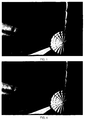
- FIG. 1 A sample picture printed with four different inks is provided in Fig. 1.
- the visible color space is a three-dimensional space for which a plurality of standard and non-standard coordinate systems have been defined.
- One standard coordinate systems includes a luminance coordinate, Y, and two chromaticity coordinates x and y.
- a method for producing a large gamut output print including the steps of providing an input digital representation of a color image in a three color input space in memory, and converting the input digital representation into an output digital representation of the color image in an at least five color output space.
- the method also includes the step of unsharp masking the input digital representation before the step of converting.
- the at least five color output space includes a no more than seven color output space.
- the step of unsharp masking is performed twice, creating first and second separately sharpened input representations
- the step of converting includes the step of converting the first and second input representations to first and second output representations, defined in approximately complementary color spaces, wherein the first and second output representations together form the output digital representation in the at least five-color output space.
- the step of unsharp masking is performed with two different sets of parameters.
- the second input representation differs in sharpness, relative to the first input representation.
- the 5 colors includes at least one of a redlike color, a greenlike color or a bluelike color.
- the 5 colors includes at least one of the following colors: orange, green and violet.
- the input digital representation represents an input medium.
- the method also includes the step of displaying the output digital representation on a monitor.
- the step of converting is performed by a LookUp Table (LUT).
- LUT LookUp Table
- the method also includes the step of printing the color image from the output digital representation in cyan-like, magenta-like, yellow-like, black-like colors and in at least one of the following group of colors: red-like, green-like and blue-like.
- the method includes the steps of prescanning an input medium to provide the input digital representation, modifying the LUT in accordance with user input, rescanning the input medium to produce a new input digital representation and converting the new input digital representation with the modified LUT.
- a method for producing a converter to convert an input digital representation in an input color space to an output digital representation in an at least five color output space including the steps of receiving a first converter being operative to perform transformations from an input color space to a four color output space and generating a second converter from the first converter, the second converter being operative to perform transformations from the input color space to an at least five color output space including the four colors and at least one extra color.
- the step of generating includes the step of nonlinearly adjusting the first converter, thereby to generate the second converter.
- the step of nonlinearly adjusting includes the step of smoothly adjusting the first converter, thereby to generate the second converter.
- the method includes the step of enabling the first converter to perform gray component replacement.
- the method includes the step of performing color correction after the step of generating.
- apparatus for producing a large gamut output image including a memory storing an input digital representation of a color image in a three color input space, and a converter which converts an input digital representation in an input color space to an output digital representation in an at least five color output space.
- the apparatus includes an unsharp mask filter, providing input to the converter, for sharpening the input digital representation.
- the at least five color color space includes a no more than seven color output space.
- the unsharp mask filter is operative to create first and second separately sharpened input representations and wherein the converter includes means for converting the first and second input representations to first and second output representations, defined in approximately complementary color spaces, wherein the first and second output representations together form the output digital representation in the at least five-color output space.
- the unsharp mask filters operate with two different sets of parameters.
- the second input representation is more sharply masked than the first input representation.
- the 5 colors includes at least one of a redlike color, a greenlike color or a bluelike color.
- the 5 colors includes at least one of the following colors: orange, green and violet.
- the step of printing includes the step of preparing half-tone separations having screen angles wherein the screen angles for the cyan-like, magenta-like, yellow-like and black-like half-tone separations include first, second, third and fourth screen angles, respectively, and the screen angles for the red-like, green-like and blue-like half-tone separations include mutually distinct ones from among the first, second, third and fourth screen angles.
- the input digital representation represents an input medium.
- the apparatus also includes a monitor and a conversion-to-monitor color space unit for converting the output digital representation for display on the monitor.
- the converter includes a LookUp Table (LUT).
- LUT LookUp Table
- the apparatus also includes an output device operative to print the color image from the output digital representation in cyan-like, magenta-like, yellow-like, black-like colors and in at least one of the following group of colors: red-like, green-like and blue-like.
- the apparatus includes a scanner for prescanning an input medium to provide the input digital representation and an image and LUT manipulator for modifying the LUT in accordance with user input, wherein the scanner also is operative to rescan the input medium to produce a new input digital representation and the converter is operative to convert the new input digital representation with the modified LUT.
- apparatus for producing a converter for converting an input digital representation in an input color space to an output digital representation in an at least five color output space including means for receiving a first converter being operative to perform transformations from an input color space to a four color output space, and a converter generating unit operative to generate a second converter from the first converter, the second converter being operative to perform transformations from the input color space to an at least five color output space including the four colors and at least one extra color.
- the converter generating unit includes means for nonlinearly adjusting the first converter, thereby to generate the second converter.
- the means for nonlinearly adjusting includes means for smoothly adjusting the first converter, thereby to generate the second converter.
- the apparatus includes a GCR unit operative to enable the first converter to perform grey color replacement.
- the apparatus includes a color correction unit receiving input from the converter generating unit.
- the output device includes means for preparing half-tone separations having screen angles wherein the screen angles for the cyan-like, magenta-like, yellow-like and black-like half-tone separations include first, second, third and fourth screen angles, respectively, and the screen angles for the red-like, green-like and blue-like half-tone separations include mutually distinct ones from among the first, second, third and fourth screen angles.
- the no more than seven color output space includes a five, six or seven color output space.
- rescanning typically refers to modification of an existing digital representation of a color image rather than to physically rescanning a color image from a physical substrate to obtain a new digital representation of the color image.
- Fig. 1 is a prior art figure which is described in the above Background section of the specification.
- the present invention is operative to provide a representation of a color image in a color space based on at least five colors.
- the at least five color color space is based on:
- Sample CMYK inks are the conventional toners manufactured by Dupont deNemours GmbH of Neu-Issenberg, Germany.
- Sample RGB inks are also manufactured by Dupont deNemours GmbH of the following toners: red formed of 90% RRT and 10% OF1, green formed of 45% GGT4, 50% GF1 and 5% YY6, and blue formed of 70% BBT5, 15% MF1 and 15% TW6.
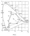
- Fig. 2 is a diagram of a printable color space, constructed and operative in accordance with the present invention, which uses more than four printing inks, more than three of which are printed at individual locations.
- Fig. 2 illustrates a two-dimensional plot of x and y color coordinates, at the origin of the Y axis.
- the visible color space 12 is not printable in its entirety when the four CMYK colors are employed.
- a surrounding dotted line 20 an approximate gamut of a printing press which utilizes the more-than-four-color scheme of the present invention is indicated by a surrounding dotted line 20.
- the approximate gamut of a printing press which utilizes a conventional four-color scheme is indicated by a surrounding solid line 17.
- Gamuts 17 and 20 of Fig. 2 are only approximations of the actual gamuts since the gamut of a press, in actual practice, is affected by idiosynchratic factors such as printing stock and printing method.
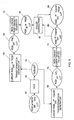
- Fig. 3 is a block diagram illustration of a system, constructed and operative in accordance with the present invention, for producing output prints using more than four colors.
- the input image to the system of Fig. 3 typically has 3 color components and is also termed herein the original RGB image or the RGB ori image, although it need not necessarily be represented in RGB.
- the input image may, for example, take the form of a memory storing a digital representation 24 provided by pre-scanning a hard copy, using a electronic color separation scanner such as Scitex's Smart Scanner or may, for example, be an input representation of an image in a 3-component input color space, arriving from a storage medium.
- the memory may comprise any suitable device from which a digital image may be retrieved, such as but not limited to a computer disk, a magnetic tape, an magneto-optical disk, an optical disk such as a compact disk, either local or, alternatively, remotely disposed and connected to the remaining components of the apparatus, as via a network.
- the memory may be accessed either directly or via a RAM.
- a particular feature of the system of Fig. 3 is that a converter-to-more-than-four-coordinates 30 is provided which receives an input digital representation of an image in a three component color coordinate system, such as RGB, and provides an output digital representation in an at least five coordinate, color coordinate system.
- the input and output digital representations each comprise a multiplicity of pixels, wherein a pixel has corresponding color density values.
- Converter 30 For each pixel of the input digital representation 24, which may, for example, comprise an RGB image, the converter 30 directly converts the input digital values to a large gamut output image 33 including a multiplicity of output digital values including both basic and extra color components.
- Converter 30 may be implemented as a LookUp Table (LUT) comprising a plurality of cells each including an address and a contents.
- the LUT is preferably stored on a suitable hardware memory element such as the image processor board of the Scitex Smart Scanner, as described in more detail hereinbelow.
- the LUT does not process neighboring pixels to determine the output digital values of a current pixel, except in that interpolation may be required to determine the output digital values of the current pixel.
- converter 30 may be implemented as a computation unit in a CPU.
- the input digital representation 24 may be processed by an unsharp mask filter 31 which is operative to sharpen the details of the input image 24, thereby to provide a sharpened image 29.
- unsharp mask filter 31 Conventional unsharp masking is described in detail in chapter 15 of the above-referenced publication by Molla.
- the output digital representation 33 is provided to a plotter or imagesetter 32, such as the Dolev plotter, commercially available from Scitex Corporation Ltd. of Herzlia, Israel.
- the plotter 32 prepares, from the output digital representation, at least five half-tone color separations (not shown), one for each one of the inks to be printed.
- the plotter 32 then plots the separations, producing thereby a set 35 of at least five color separation films.
- plotter 32 may be replaced by a proofer, such as one of the proofers manufactured by Iris Graphics, Inc. of Bedford, Ma., U.S.A.
- the color separation films 35 are provided to a printing press 34 which prints a large gamut output print 36 therefrom.
- a sample output print 36 illustrating the same color image illustrated in Fig. 1 but in more than four colors, resulting in a sharper, better defined image, is illustrated in Fig. 4.
- the apparatus of Fig. 3 optionally comprises a large gamut image manipulator 37 which performs conventional color corrections on the LUTs of four color converter 30 and/or on the large gamut output image 33.
- the color correction functionalities of manipulator 37 may be similar to those of color correction unit 90 of Fig. 5 which is described in detail below.
- the image manipulation device 37 is also preferably operative to perform cropping, rotation, using specialized filters, and other image manipulations operations which are known in the art in response to commands from a user. For color correction operations, gradations, grey component replacement (GCR), under color removal and addition (UCR and UCA), the image manipulation device 37 modifies the converter 30.
- GCR grey component replacement
- UCA under color removal and addition
- the image manipulation device 37 can perform the full range of color manipulations and, in some cases, can increase the gamut of the output print. This is in contrast to certain state of the art systems which manipulate an input image provided in an ink-based output color space.
- the input image is reconverted, using the converter 30 after manipulation by manipulator 37, and a final large gamut digital representation 33 is produced.
- the input image is provided by a scanning device
- the input medium is typically rescanned and the output of the scanning device is converted utilizing the converter 30 after manipulation by manipulator 37.
- the input image may be manipulated directly by the manipulator 37, rather than being converted by the converter 30 which has been manipulated by manipulator 37.
- the apparatus of Fig. 3 also preferably comprises a monitor 38 for on-line display of a representation of the large gamut output image 36.
- a converter-to-monitor-RGB 39 is operative to convert the more-than-four color representation of image 36 into the coordinates of the monitor.
- the converter-to-monitor-RGB unit 39 may, for example, be implemented on the VIP2 board of a Scitex Whisper workstation.
- Fig. 5 is a block diagram illustration of a system for generating a LUT 88 which is suitable for implementing converter 30 of Fig. 3.
- the apparatus of Fig. 5 includes a conventional lookup table 40 which is operative to convert input RGB values, labeled RGB ori , to conventional four color output, such as but not limited to conventional CMYK output, as indicated by the label CMYK cnv .
- the CMYK cnv output of LUT 40 is received by an optional grey color replacer (GCR) 42 which is operative to modify the output values of each cell in LUT 40 such that black color is used to provide grey values.
- GCR grey color replacer
- GCR 42 comprising CMYK(GCR) cnv output
- units 46 and 48 may be provided to units 46 and 48, both of which are described in more detail below.
- a single GCR LUT 44 is constructed which has the functionalities of LUT 40 and GCR unit 42 combined and which therefore replaces LUT 40 and GCR unit 42.
- units 46 and 48 receive CMYK(GCR) cnv output from GCR LUT 44.
- the GCR elements may be omitted and units 46 and 48 may receive CMYK cnv output directly from LUT 40.
- Units 46 and 70 employ the CMYK(GCR) cnv output or the CMYK cnv output, both of which are referred to generally below as CMYK cnv output, to generate, in a two stage procedure, a LUT 84 which receives an input digital image in RGB ori and creates a digital image in the "RGB" color coordinate system.
- the RGB ori values are linearly transformed by linear transformation generator 46 to obtain a preliminary "RGB” representation, also termed herein the E i representation.
- the preliminary "RGB” or E i representation is adjusted by nonlinear "RGB” color density adjuster 70 for nonlinearities.
- the output of the second stage is a nonlinear transformation from RGB ori directly to the final "RGB” representation, which nonlinear transformation is stored in LUT 84.
- Units 48 and 72 employ the CMYK(GCR) cnv output or the CMYK cnv output, both of which are referred to generally below as CMYK cnv output, to generate, in a two stage procedure, a LUT 86 which receives an input digital image in RGB ori and creates a digital image in the "CMYK" color coordinate system.
- the RGB ori values are linearly transformed by linear transformation generator 48 to obtain a preliminary "CMYK” representation, also termed herein the L i representation.
- the preliminary "CMYK” or L i representation is adjusted by nonlinear "CMYK” color density adjuster 72 for non-linearities.
- the output of the second stage is a nonlinear transformation from RGB ori directly to the final "CMYK” representation, which nonlinear transformation is stored in LUT 86.
- Sample values for the ⁇ ij are:
- generator 46 determines, for each cell in GCR LUT 44, the extent of the extra colors needed, over and above the basic colors.
- Generator 46 is only operative to determine the amount of extra "RGB” color needed.
- Generator 48 is operative to adjust, or typically to reduce, the amount of "CMYK” color needed in response to the addition of the extra "RGB” color.
- Generator 48 determines, for each cell in LUT 44, a suitable amount of each basic color from among the basic "CMYK” colors, given the amount of extra ink to be employed.
- Units 46 and 48 generate transformations, represented in Fig. 5 as LUTs 50 and 52 respectively although in practice it is not necessary to represent these transformations as LUTs.
- LUT 50 transforms RGB ori values into E i values.
- LUT 52 transforms RGB ori values into L i values.
- LUTs 50 and 52 E i and L i respectively
- nonlinear color density adjusters 70 and 72 which generate adjusted extra color values, termed herein “RGB” values, and adjusted basic color values, termed herein “CMYK” values, respectively.
- LUTs 50 and 52 Despite the compensation of inks provided by generators 46 and 48, LUTs 50 and 52 produce output representations requiring too much ink, per pixel, to be used in the output print 36. Therefore, LUTs 50 and 52 are provided to respective nonlinear color density adjusters 70 and 72 which nonlinearly adjust the color density levels in the output representations generated by LUTs 50 and 52 respectively.
- Nonlinear color density adjuster 70 replaces the extra color density values with adjusted values, in accordance with the curve shown in Fig. 7A.
- the curve of Fig. 7A graphs input color density with output color density, for the extra colors. If the color density adjuster did not operate, the dotted curve 74 would be operative. Typically, the extra colors are useful only at their higher densities. At their lower densities, the combination of the basic colors provides acceptable colors. Thus, the curves of Fig. 7A tend to be far from curve 74 at the low densities and close to it at the high densities.
- Ink density adjuster 70 may perform any type of nonlinear operation; for example, it might operate in accordance with an exponential curve 76, or over only a small range, as shown by curve 78. Any form of curve which is below curve 74 is suitable, as long as the minimum and maximum values of color density are not affected.
- Ink density adjuster 72 performs any type of adjustment operation.
- Three sample adjustment curves 82 are provided in Fig. 7B.
- the curve of Fig. 7B graphs input color density with output color density, for the basic colors. If the color density adjuster did not operate, the dotted curve 80 would be operative.
- the basic colors are most useful at their lower densities. At their higher densities, the extra colors provide the high quality color.
- the curves of Fig. 7B tend to be close to curve 80 at the low densities and far from to it at the high densities.
- Ink density adjusters 70 and 72 generate LUTs 84 and 86 respectively.
- LUT 84 transforms RGB ori values to "RGB” values.
- LUT 86 transforms RGB ori values to "CMYK” values. Together, LUTs 84 and 86 provide a conversion from RGB ori to "RGBCMYK”.
- LUTs 84 and 86 may be combined to a single LUT 88, the output of which is a concatenation of the outputs of LUTs 84 and 86.
- LUTs 84 and 86 may, if desired, be updated or modified through the use of a color correction unit 90, such as the color correction unit marketed by Scitex Corporation together with Scitex's Smart Scanner.
- the color correction unit 90 modifies the "RGBCMYK" values as requested by a user.
- the user might request a global color change, in which case, the contents of many of the cells in the LUTs 84 and 86, or, if they have been combined, in LUT 88, are modified.
- Local color corrections operative in a portion of the color space rather than in the entire color space, can also be effected.
- Units 46, 48, 70 and 72 may, for example be based on a suitable CPU or other processing unit such as a Whisper workstation equipped with HSP boards, commercially available from Scitex Corporation.
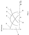
- Fig. 6 is a saturation vs. hue graph which conceptually illustrates the areas of influence of two sample basic colors, cyan and magenta, and the extra color whose hue is between them, which is, in this case, blue.
- Fig. 6 illustrates curves 54 and 56, for cyan and magenta, respectively, which overlap in an area 58. In this area, both cyan and magenta are utilized to produce a color.
- the hue of each extra color (“RGB”) is traditionally represented by a combination of the basic colors (“CMYK”), as shown in the hue-saturation diagram of Fig. 6.
- CMYK the basic colors
- Fig. 6 the blue color is utilized for all colors falling within the area under the blue curve 60. Those within a section 62 are produced with blue color only, those within a section 64 with cyan and blue, those within a section 66 with magenta and blue, and those within area 58, with cyan, magenta and blue.
- the extra color curve 60 which is a blue curve in the example of Fig. 6, is designed to smoothly generate more saturated colors as one varies the densities of the cyan, blue and magenta inks. Similar curves characterize other extra colors such as red and green.
- This smoothness constraint is implemented by ensuring that partial differentials of the above equations defining "RGB” and "CMYK", for the E i 's and L i 's in the area around t i or t i ', exist.
- Fig. 8 is a modification of the apparatus of Fig. 3 in which the more-than-four-color converter 30 is replaced by a basic color converter 110 and an extra color converter 112.
- the more-than-four-color converter 30 of Fig. 3 typically converts an input image including a plurality of basic color components into an output image including the same plurality of basic color components, having different values, and also including a plurality of extra color components.
- extra color converter 112 converts an input image 105 including a plurality of conventional color components into an output subimage, referenced as "RGB” image 113 in Fig. 8, which includes only a plurality of extra color components and not the original, conventional color components.
- Basic color converter 110 converts an input image including a plurality of conventional color components into an output subimage, referenced "CMYK” image 115 in Fig. 8, which includes the same plurality of basic color components, having values which take into account the role of the plurality of extra color components.
- Basic and extra color converters 110 and 112 may respectively comprise LUTs 86 and 84 of Fig. 5, respectively.
- the processing route of Fig. 3, which includes unsharp masking, color conversion, image manipulation and monitor display is replaced, in the embodiment of Fig. 8, by two processing routes.
- Fig. 8 is particularly suitable for applications in which a system is only capable of operating on digital representations of four or fewer values per pixel, because it allows the input representation 24 to be separately processed to produce basic color and extra color output representations.
- a system is only capable of operating on digital representations of four or fewer values per pixel, because it allows the input representation 24 to be separately processed to produce basic color and extra color output representations.
- unsharp masking unit 31 of Fig. 3 is preferably replaced by two unsharp mask filters 106 and 108 which are operative to sharpen the details of input representation 24 to different extents.
- Unsharp masker 108 corresponding to the "extra color component" processing route, typically provides greater sharpening than USM 106. Thus, the extra color will be utilized to sharpen the details of the output print. If the processing is sequential, USMs 106 and 108 are implemented as a single USM having two parameter sets.
- Converters 110 and 112 are typically modified, in response to user commands, by respective image manipulators 114 and 116, which replace image manipulator 37 of Fig. 3.
- the input digital representation is reconverted, via the updated versions of converters 110 and 112 and in accordance with any image modifying parameters, and final output representations 113 and 115 are produced.
- the input digital representation is provided by a scanning device
- the input medium is typically rescanned and the output (e.g. the input representation) of the scanning device is converted utilizing the updated converters 110 and 112.
- the extra and basic color images 113 and 115 are preferably separately or sequentially displayed on a monitor 102, replacing monitor 38 of Fig. 3.
- Converter -to-monitor unit 39 of Fig. 3 is replaced by a conventional color image converter 118 which converts the basic color image 115 to monitor coordinates and by an extra color image converter 120 which converts the extra color image 113 to monitor coordinates.
- the final output representations 113 and 115 are provided to the plotter 32, as described hereinabove with respect to Fig. 3, and the color separation films produced thereby are provided to the press 34, for producing the large gamut print 36.
- Fig. 9A is a color illustration of a four-color subimage, generated using the "basic color component" processing route of Fig. 8.
- Fig. 9B is a color illustration of a three-color subimage, generated using the "extra color component” processing route of Fig. 8.
- the two subimages of Figs. 9A and 9B together include substantially the same information as does the 7-color image of Fig. 4.
- Fig. 9A is quite similar to Fig. 1, but that its colors are somewhat less saturated.
- Fig. 9B indicates the locations where the extra colors are to be placed, which correspond to the portions of Fig. 4 which are sharper than in Fig. 1.
- Figs. 3 and 8 are operative for applications in which input media is scanned and the data converted to more than four color output representations, as well as applications in which already scanned input representations in a 3-component input color space are received.
- Sample sources for light-based color space representations are image creation and/or manipulation systems such as the Blaze, manufactured by Scitex Corporation or such as PHOTOSHOP, manufactured by Adobe Systems Inc. of Mountainview, Ca., U.S.A.
- a three-component input space such as a light based color space is typically converted to an output color space based on inks, toners or other color output materials.
- printing as used in the present specification is intended to refer to any process whereby a visually perceptible representation of an image is provided, such as processes employing proofers, presses, imagesetters, pressproofers, and second generation output devices.
Landscapes
- Engineering & Computer Science (AREA)
- Multimedia (AREA)
- Signal Processing (AREA)
- Textile Engineering (AREA)
- Facsimile Image Signal Circuits (AREA)
- Color Image Communication Systems (AREA)
- Image Processing (AREA)
- Printing Methods (AREA)
- Dot-Matrix Printers And Others (AREA)
Abstract
Description
- The present invention relates to more than four color printing systems generally.
- Conventional color printing presses typically print output prints with four or fewer inks, where the inks are typically cyan, magenta, yellow and black (CMYK). For each ink color, a color separation film is produced, marking the locations where the specific ink is to be placed.
- The press places ink on the output print four times, one for each color, in accordance with the corresponding color separation films. The resultant colors are combinations of the colors of the printed inks.
- Color separation and color printing are described in detail in the publication, the disclosure of which is incorporated herein by reference:
Electronic Color Separation, by R.K Molla, published by Chapman Printing Company, Parkersburg, W. Virginia, U.S.A., 1988. - A sample picture printed with four different inks is provided in Fig. 1.
- The visible color space is a three-dimensional space for which a plurality of standard and non-standard coordinate systems have been defined. One standard coordinate systems includes a luminance coordinate, Y, and two chromaticity coordinates x and y.
- When it is desired to print a color outside the gamut of the printing press, it is known in the art to overprint an additional ink, typically of the desired color, in certain areas of the image. For example, if a photograph of an automobile is being reproduced and the color of the automobile is a specific red not within the gamut of the printing press, a special ink, of the desired red, is selected and an additional color separation film is produced to indicate where the extra ink is to be placed in additional to the regular printing inks.
- The process of utilizing an extra color separation is known in the art as "touch-plate" printing and is common for high quality printing.
- An article by Harald Kuppers, entitled "Printing by Septichromy", appeared as an extract of a conference given by Kuppers at a Colorix Seminary in Paris. The Kuppers article suggests that, to increase the gamut of a printing press, two colors, plus a black color, may be selected from among seven specific colors including a black color.
- It is an object of the present invention to provide a system and method for printing in more than four colors.
- There is therefore provided, in accordance with a preferred embodiment of the present invention, a method for producing a large gamut output print, the method including the steps of providing an input digital representation of a color image in a three color input space in memory, and converting the input digital representation into an output digital representation of the color image in an at least five color output space.
- Further in accordance with a preferred embodiment of the present invention, the method also includes the step of unsharp masking the input digital representation before the step of converting.
- Still further in accordance with a preferred embodiment of the present invention, the at least five color output space includes a no more than seven color output space.
- Additionally in accordance with a preferred embodiment of the present invention, the step of unsharp masking is performed twice, creating first and second separately sharpened input representations, and wherein the step of converting includes the step of converting the first and second input representations to first and second output representations, defined in approximately complementary color spaces, wherein the first and second output representations together form the output digital representation in the at least five-color output space.
- Further in accordance with a preferred embodiment of the present invention, the step of unsharp masking is performed with two different sets of parameters.
- Still further in accordance with a preferred embodiment of the present invention, the second input representation differs in sharpness, relative to the first input representation.
- Further in accordance with a preferred embodiment of the present invention, the 5 colors includes at least one of a redlike color, a greenlike color or a bluelike color.
- Still further in accordance with a preferred embodiment of the present invention, the 5 colors includes at least one of the following colors: orange, green and violet.
- Additionally in accordance with a preferred embodiment of the present invention, the input digital representation represents an input medium.
- Further in accordance with a preferred embodiment of the present invention, the method also includes the step of displaying the output digital representation on a monitor.
- Still further in accordance with a preferred embodiment of the present invention, the step of converting is performed by a LookUp Table (LUT).
- Additionally in accordance with a preferred embodiment of the present invention, the method also includes the step of printing the color image from the output digital representation in cyan-like, magenta-like, yellow-like, black-like colors and in at least one of the following group of colors: red-like, green-like and blue-like.
- Further in accordance with a preferred embodiment of the present invention, the method includes the steps of prescanning an input medium to provide the input digital representation, modifying the LUT in accordance with user input, rescanning the input medium to produce a new input digital representation and converting the new input digital representation with the modified LUT.
- There is also provided, in accordance with a preferred embodiment of the present invention, a method for producing a converter to convert an input digital representation in an input color space to an output digital representation in an at least five color output space, the method including the steps of receiving a first converter being operative to perform transformations from an input color space to a four color output space and generating a second converter from the first converter, the second converter being operative to perform transformations from the input color space to an at least five color output space including the four colors and at least one extra color.
- Further in accordance with a preferred embodiment of the present invention, the step of generating includes the step of nonlinearly adjusting the first converter, thereby to generate the second converter.
- Still further in accordance with a preferred embodiment of the present invention, the step of nonlinearly adjusting includes the step of smoothly adjusting the first converter, thereby to generate the second converter.
- Further in accordance with a preferred embodiment of the present invention, the method includes the step of enabling the first converter to perform gray component replacement.
- Additionally in accordance with a preferred embodiment of the present invention, the method includes the step of performing color correction after the step of generating.
- There is also provided, in accordance with a preferred embodiment of the present invention, apparatus for producing a large gamut output image including a memory storing an input digital representation of a color image in a three color input space, and a converter which converts an input digital representation in an input color space to an output digital representation in an at least five color output space.
- Further in accordance with a preferred embodiment of the present invention, the apparatus includes an unsharp mask filter, providing input to the converter, for sharpening the input digital representation.
- Still further in accordance with a preferred embodiment of the present invention, the at least five color color space includes a no more than seven color output space.
- Still further in accordance with a preferred embodiment of the present invention, the unsharp mask filter is operative to create first and second separately sharpened input representations and wherein the converter includes means for converting the first and second input representations to first and second output representations, defined in approximately complementary color spaces, wherein the first and second output representations together form the output digital representation in the at least five-color output space.
- Further in accordance with a preferred embodiment of the present invention, the unsharp mask filters operate with two different sets of parameters.
- Still further in accordance with a preferred embodiment of the present invention, the second input representation is more sharply masked than the first input representation.
- Further in accordance with a preferred embodiment of the present invention, the 5 colors includes at least one of a redlike color, a greenlike color or a bluelike color.
- Still further in accordance with a preferred embodiment of the present invention, the 5 colors includes at least one of the following colors: orange, green and violet.
- Further in accordance with a preferred embodiment of the present invention, the step of printing includes the step of preparing half-tone separations having screen angles wherein the screen angles for the cyan-like, magenta-like, yellow-like and black-like half-tone separations include first, second, third and fourth screen angles, respectively, and the screen angles for the red-like, green-like and blue-like half-tone separations include mutually distinct ones from among the first, second, third and fourth screen angles.
- Still further in accordance with a preferred embodiment of the present invention, the input digital representation represents an input medium.
- Further in accordance with a preferred embodiment of the present invention, the apparatus also includes a monitor and a conversion-to-monitor color space unit for converting the output digital representation for display on the monitor.
- Still further in accordance with a preferred embodiment of the present invention, the converter includes a LookUp Table (LUT).
- Additionally in accordance with a preferred embodiment of the present invention, the apparatus also includes an output device operative to print the color image from the output digital representation in cyan-like, magenta-like, yellow-like, black-like colors and in at least one of the following group of colors: red-like, green-like and blue-like.
- Further in accordance with a preferred embodiment of the present invention, the apparatus includes a scanner for prescanning an input medium to provide the input digital representation and an image and LUT manipulator for modifying the LUT in accordance with user input, wherein the scanner also is operative to rescan the input medium to produce a new input digital representation and the converter is operative to convert the new input digital representation with the modified LUT.
- There is also provided, in accordance with a preferred embodiment of the present invention, apparatus for producing a converter for converting an input digital representation in an input color space to an output digital representation in an at least five color output space, the apparatus including means for receiving a first converter being operative to perform transformations from an input color space to a four color output space, and a converter generating unit operative to generate a second converter from the first converter, the second converter being operative to perform transformations from the input color space to an at least five color output space including the four colors and at least one extra color.
- Further in accordance with a preferred embodiment of the present invention, the converter generating unit includes means for nonlinearly adjusting the first converter, thereby to generate the second converter.
- Still further in accordance with a preferred embodiment of the present invention, the means for nonlinearly adjusting includes means for smoothly adjusting the first converter, thereby to generate the second converter.
- Additionally in accordance with a preferred embodiment of the present invention, the apparatus includes a GCR unit operative to enable the first converter to perform grey color replacement.
- Further in accordance with a preferred embodiment of the present invention, the apparatus includes a color correction unit receiving input from the converter generating unit.
- Still further in accordance with a preferred embodiment of the present invention, the output device includes means for preparing half-tone separations having screen angles wherein the screen angles for the cyan-like, magenta-like, yellow-like and black-like half-tone separations include first, second, third and fourth screen angles, respectively, and the screen angles for the red-like, green-like and blue-like half-tone separations include mutually distinct ones from among the first, second, third and fourth screen angles.
- Further in accordance with a preferred embodiment of the present invention, the no more than seven color output space includes a five, six or seven color output space.
- The term "rescanning" in the present specification typically refers to modification of an existing digital representation of a color image rather than to physically rescanning a color image from a physical substrate to obtain a new digital representation of the color image.
- The present invention will be understood and appreciated more fully from the following detailed description taken in conjunction with the drawings and appendices in which:
- Fig. 1 is a color illustration of a color image generated using prior art four-color printing techniques;
- Fig. 2 is a diagram of a printable color space, constructed and operative in accordance with the present invention, which uses more than four printing inks, more than three of which are printed at individual locations;
- Fig. 3 is a block diagram illustration of a system, constructed and operative in accordance with the present invention, for producing output prints using more than four colors;
- Fig. 4 is a color illustration of the color image of Fig. 1, generated using the more-than-four-color printing technique of the present invention;
- Fig. 5 is a block diagram illustration of a system for generating a converter useful in the system of Fig. 4;
- Fig. 6 is a hue-saturation diagram;
- Figs. 7A and 7B are diagrams of transformations useful in implementing the system of Fig. 5;
- Fig. 8 is a block diagram of a system which is a modification of the system of Fig. 3;
- Fig. 9A is a color illustration of a four-color subimage, generated using the apparatus of Fig. 8, which represents the color image of Figs. 1 and 5 when taken together with the subimage of Fig. 9B;
- Fig. 9B is a color illustration of a three-color subimage, generated using the apparatus of Fig. 8, which represents the color image of Figs. 1 and 5 when taken together with the subimage of Fig. 9A; and
- Appendix A is a computer listing of a best mode method for receiving a LUT such as
LUT 40 of Fig. 5 and constructingLUTs - Fig. 1 is a prior art figure which is described in the above Background section of the specification.
- The present invention is operative to provide a representation of a color image in a color space based on at least five colors. In accordance with a preferred embodiment of the present invention, the at least five color color space is based on:
- a. Four colors, termed herein "CMYK-like" colors or "CMYK" colors or "basic" colors, which typically include three colors which approximately span the printing color space and which typically although not necessarily resemble cyan, magenta and yellow, respectively; and a fourth black-like color; and
- b. One, two or three additional colors, termed herein "RGB"-like or "RGB" or "extra" colors, comprising one, two or three colors from among a set of three colors which approximately span the printing color space and which typically approximately complement the CMY-like "basic" colors. The three extra colors are typically respectively redlike, bluelike and greenlike in appearance. The terms "redlike", "bluelike" and "greenlike" are intended here to be interpreted broadly and to include, for example, orange, green and violet (OGV colors), respectively.
- Sample CMYK inks are the conventional toners manufactured by Dupont deNemours GmbH of Neu-Issenberg, Germany. Sample RGB inks are also manufactured by Dupont deNemours GmbH of the following toners: red formed of 90% RRT and 10% OF1, green formed of 45% GGT4, 50% GF1 and 5% YY6, and blue formed of 70% BBT5, 15% MF1 and 15% TW6.
- Fig. 2 is a diagram of a printable color space, constructed and operative in accordance with the present invention, which uses more than four printing inks, more than three of which are printed at individual locations.
- Specifically, Fig. 2 illustrates a two-dimensional plot of x and y color coordinates, at the origin of the Y axis. The entire visible spectrum, having wavelengths varying from 380 nm - 770 nanometers, is indicated by a
curve 10 having an interior 12. The luminance quality, or the effect of black on thespace 12, corresponds to an axis which perpendicularly intersects the plot of Fig. 2. - The
visible color space 12 is not printable in its entirety when the four CMYK colors are employed. In Fig. 2, an approximate gamut of a printing press which utilizes the more-than-four-color scheme of the present invention is indicated by a surrounding dottedline 20. The approximate gamut of a printing press which utilizes a conventional four-color scheme is indicated by a surroundingsolid line 17. Gamuts 17 and 20 of Fig. 2 are only approximations of the actual gamuts since the gamut of a press, in actual practice, is affected by idiosynchratic factors such as printing stock and printing method. - Reference is now made to Fig. 3 which is a block diagram illustration of a system, constructed and operative in accordance with the present invention, for producing output prints using more than four colors. The input image to the system of Fig. 3 typically has 3 color components and is also termed herein the original RGB image or the RGBori image, although it need not necessarily be represented in RGB. The input image may, for example, take the form of a memory storing a
digital representation 24 provided by pre-scanning a hard copy, using a electronic color separation scanner such as Scitex's Smart Scanner or may, for example, be an input representation of an image in a 3-component input color space, arriving from a storage medium. - The memory may comprise any suitable device from which a digital image may be retrieved, such as but not limited to a computer disk, a magnetic tape, an magneto-optical disk, an optical disk such as a compact disk, either local or, alternatively, remotely disposed and connected to the remaining components of the apparatus, as via a network. The memory may be accessed either directly or via a RAM.
- A particular feature of the system of Fig. 3 is that a converter-to-more-than-four-
coordinates 30 is provided which receives an input digital representation of an image in a three component color coordinate system, such as RGB, and provides an output digital representation in an at least five coordinate, color coordinate system. The input and output digital representations each comprise a multiplicity of pixels, wherein a pixel has corresponding color density values. - For each pixel of the input
digital representation 24, which may, for example, comprise an RGB image, theconverter 30 directly converts the input digital values to a largegamut output image 33 including a multiplicity of output digital values including both basic and extra color components.Converter 30 may be implemented as a LookUp Table (LUT) comprising a plurality of cells each including an address and a contents. The LUT is preferably stored on a suitable hardware memory element such as the image processor board of the Scitex Smart Scanner, as described in more detail hereinbelow. Typically, the LUT does not process neighboring pixels to determine the output digital values of a current pixel, except in that interpolation may be required to determine the output digital values of the current pixel. Alternatively,converter 30 may be implemented as a computation unit in a CPU. - Apparatus for generating a
converter 30 is described herein in detail with reference to Fig. 5. - Optionally, before conversion by
converter 30, the inputdigital representation 24 may be processed by anunsharp mask filter 31 which is operative to sharpen the details of theinput image 24, thereby to provide a sharpenedimage 29. Conventional unsharp masking is described in detail in chapter 15 of the above-referenced publication by Molla. - The output
digital representation 33 is provided to a plotter orimagesetter 32, such as the Dolev plotter, commercially available from Scitex Corporation Ltd. of Herzlia, Israel. Theplotter 32 prepares, from the output digital representation, at least five half-tone color separations (not shown), one for each one of the inks to be printed. Theplotter 32 then plots the separations, producing thereby aset 35 of at least five color separation films. - Alternatively,
plotter 32 may be replaced by a proofer, such as one of the proofers manufactured by Iris Graphics, Inc. of Bedford, Ma., U.S.A. - The following is a sample set of screen angles that has been found effective for more than four color printing:
- Cyan and Red:
- 112.5°
- Magenta and Green:
- -7.5°
- Yellow:
- 97.5°
- Black and Blue:
- 52.5°
- The
color separation films 35 are provided to aprinting press 34 which prints a largegamut output print 36 therefrom. Asample output print 36, illustrating the same color image illustrated in Fig. 1 but in more than four colors, resulting in a sharper, better defined image, is illustrated in Fig. 4. - The apparatus of Fig. 3 optionally comprises a large
gamut image manipulator 37 which performs conventional color corrections on the LUTs of fourcolor converter 30 and/or on the largegamut output image 33. The color correction functionalities ofmanipulator 37 may be similar to those ofcolor correction unit 90 of Fig. 5 which is described in detail below. - The
image manipulation device 37 is also preferably operative to perform cropping, rotation, using specialized filters, and other image manipulations operations which are known in the art in response to commands from a user. For color correction operations, gradations, grey component replacement (GCR), under color removal and addition (UCR and UCA), theimage manipulation device 37 modifies theconverter 30. - Due to the direct correspondence between the input and output representations, the
image manipulation device 37 can perform the full range of color manipulations and, in some cases, can increase the gamut of the output print. This is in contrast to certain state of the art systems which manipulate an input image provided in an ink-based output color space. - When the user has finished manipulating the
converter 30, the input image is reconverted, using theconverter 30 after manipulation bymanipulator 37, and a final large gamutdigital representation 33 is produced. For example, if the input image is provided by a scanning device, the input medium is typically rescanned and the output of the scanning device is converted utilizing theconverter 30 after manipulation bymanipulator 37. - Alternatively, the input image may be manipulated directly by the
manipulator 37, rather than being converted by theconverter 30 which has been manipulated bymanipulator 37. - The apparatus of Fig. 3 also preferably comprises a
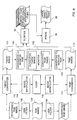
monitor 38 for on-line display of a representation of the largegamut output image 36. A converter-to-monitor-RGB 39 is operative to convert the more-than-four color representation ofimage 36 into the coordinates of the monitor. The converter-to-monitor-RGB unit 39 may, for example, be implemented on the VIP2 board of a Scitex Whisper workstation. - Fig. 5 is a block diagram illustration of a system for generating a
LUT 88 which is suitable for implementingconverter 30 of Fig. 3. - The apparatus of Fig. 5 includes a conventional lookup table 40 which is operative to convert input RGB values, labeled RGBori, to conventional four color output, such as but not limited to conventional CMYK output, as indicated by the label CMYKcnv. The CMYKcnv output of
LUT 40 is received by an optional grey color replacer (GCR) 42 which is operative to modify the output values of each cell inLUT 40 such that black color is used to provide grey values. Conventional GCR techniques are described in detail in Chapter 14 of the above-referenced publication by Molla. - The output of
GCR 42, comprising CMYK(GCR)cnv output, may be provided tounits single GCR LUT 44 is constructed which has the functionalities ofLUT 40 andGCR unit 42 combined and which therefore replacesLUT 40 andGCR unit 42. According to this embodiment,units GCR LUT 44. - Alternatively, the GCR elements may be omitted and
units LUT 40. -
Units LUT 84 which receives an input digital image in RGBori and creates a digital image in the "RGB" color coordinate system. In the first stage, the RGBori values are linearly transformed bylinear transformation generator 46 to obtain a preliminary "RGB" representation, also termed herein the Ei representation. In the second stage, the preliminary "RGB" or Ei representation is adjusted by nonlinear "RGB"color density adjuster 70 for nonlinearities. The output of the second stage is a nonlinear transformation from RGBori directly to the final "RGB" representation, which nonlinear transformation is stored inLUT 84. -
Units LUT 86 which receives an input digital image in RGBori and creates a digital image in the "CMYK" color coordinate system. In the first stage, the RGBori values are linearly transformed bylinear transformation generator 48 to obtain a preliminary "CMYK" representation, also termed herein the Li representation. In the second stage, the preliminary "CMYK" or Li representation is adjusted by nonlinear "CMYK"color density adjuster 72 for non-linearities. The output of the second stage is a nonlinear transformation from RGBori directly to the final "CMYK" representation, which nonlinear transformation is stored inLUT 86. - For example, Ei values may be generated as follows:
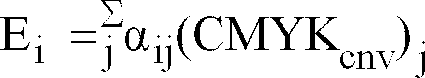
where:
j = 1, 2, 3, 4;
i = 1, 2, 3;
(CMYKcnv)j = the j'th component of a set of conventional or GCR-conventional C, M, Y and K components; and
the alpha values all satisfy -1.0 <= αij <= 1.0 and may, for example, have the following values:

- For example, Li values may be generated as follows:
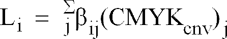
where
j = 1, 2, 3, 4;
i = 1, 2, 3, 4;
(CMYKcnv)j = the j'th component of a set of conventional or GCR-conventional C, M, Y and K components; and
the beta values satisfy -1.0 <=βij <= 1.0. Sample values for the βij are:
- More generally,
generator 46 determines, for each cell inGCR LUT 44, the extent of the extra colors needed, over and above the basic colors. -
Generator 46 is only operative to determine the amount of extra "RGB" color needed.Generator 48 is operative to adjust, or typically to reduce, the amount of "CMYK" color needed in response to the addition of the extra "RGB" color. -
Generator 48 determines, for each cell inLUT 44, a suitable amount of each basic color from among the basic "CMYK" colors, given the amount of extra ink to be employed. -
Units LUTs LUT 50 transforms RGBori values into Ei values.LUT 52 transforms RGBori values into Li values. - The output of
LUTs color density adjusters - Despite the compensation of inks provided by
generators LUTs output print 36. Therefore,LUTs color density adjusters LUTs - Nonlinear
color density adjuster 70 replaces the extra color density values with adjusted values, in accordance with the curve shown in Fig. 7A. The curve of Fig. 7A graphs input color density with output color density, for the extra colors. If the color density adjuster did not operate, the dottedcurve 74 would be operative. Typically, the extra colors are useful only at their higher densities. At their lower densities, the combination of the basic colors provides acceptable colors. Thus, the curves of Fig. 7A tend to be far fromcurve 74 at the low densities and close to it at the high densities. -
Ink density adjuster 70 may perform any type of nonlinear operation; for example, it might operate in accordance with anexponential curve 76, or over only a small range, as shown bycurve 78. Any form of curve which is belowcurve 74 is suitable, as long as the minimum and maximum values of color density are not affected. -
Density adjuster 70 may, for example, perform the following computation in order to generate "RGB" components from Ei components:
where:
i = 1, 2, 3;
Di and ti are predetermined integer color percentages, such as 100 and 30 percent, respectively, for all i; and
s(i) and qi are real numbers, such as 1.01 and 1.0, respectively, for all i. -
Ink density adjuster 72 performs any type of adjustment operation. Three sample adjustment curves 82 are provided in Fig. 7B. The curve of Fig. 7B graphs input color density with output color density, for the basic colors. If the color density adjuster did not operate, the dottedcurve 80 would be operative. Typically, the basic colors are most useful at their lower densities. At their higher densities, the extra colors provide the high quality color. Thus, the curves of Fig. 7B tend to be close tocurve 80 at the low densities and far from to it at the high densities. -
Density adjuster 72 may, for example, perform the following computation in order to generate "CMYK" values from Li values: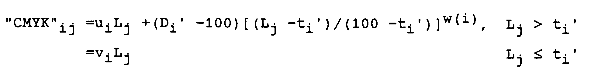
where:
i = 1, 2, 3 or i = 1, 2, 3, 4;
j = ti', ti'+1, ..., Di' (Di' >= ti')
Di' and ti' are predetermined percent color density values; and
w(i), ui and vi are real numbers. - For example, the output of
adjuster 72 may be CMY values (i = 1, 2, 3) and the following values may be used for the various parameters, for all i: Di' is 85 percent color density, ti' is 10 percent color density, w(i) is 0.3, ui, is 1.0 and vi is 1.0. -
Ink density adjusters LUTs LUT 84 transforms RGBori values to "RGB" values.LUT 86 transforms RGBori values to "CMYK" values. Together,LUTs LUTs single LUT 88, the output of which is a concatenation of the outputs ofLUTs -
LUTs color correction unit 90, such as the color correction unit marketed by Scitex Corporation together with Scitex's Smart Scanner. Thecolor correction unit 90 modifies the "RGBCMYK" values as requested by a user. The user might request a global color change, in which case, the contents of many of the cells in theLUTs LUT 88, are modified. Local color corrections, operative in a portion of the color space rather than in the entire color space, can also be effected. - Conventional color correction techniques are described in
chapter 10 of the above referenced publication by Molla. -
Units - Fig. 6 is a saturation vs. hue graph which conceptually illustrates the areas of influence of two sample basic colors, cyan and magenta, and the extra color whose hue is between them, which is, in this case, blue. Fig. 6 illustrates
curves area 58. In this area, both cyan and magenta are utilized to produce a color. - Given that the hues of the extra colors typically lie between the hues of the basic printing colors, generally, the hue of each extra color ("RGB") is traditionally represented by a combination of the basic colors ("CMYK"), as shown in the hue-saturation diagram of Fig. 6. However, the saturation of the extra colors is much larger.
- In Fig. 6, the blue color is utilized for all colors falling within the area under the
blue curve 60. Those within asection 62 are produced with blue color only, those within asection 64 with cyan and blue, those within asection 66 with magenta and blue, and those withinarea 58, with cyan, magenta and blue. - The
extra color curve 60, which is a blue curve in the example of Fig. 6, is designed to smoothly generate more saturated colors as one varies the densities of the cyan, blue and magenta inks. Similar curves characterize other extra colors such as red and green. This smoothness constraint is implemented by ensuring that partial differentials of the above equations defining "RGB" and "CMYK", for the Ei's and Li's in the area around ti or ti', exist. - It will be appreciated that the apparatus shown hereinabove is not restricted to applications in which there are three extra colors but is also useful for applications in which there are only one or two extra colors. In these applications, there are only one or two Ei values and only one or two components from among the "R", "G" and "B" extra color components. The number of Li values and the number of basic color components remains unchanged, although the values themselves might change.
- Reference is now made to Fig. 8 which is a modification of the apparatus of Fig. 3 in which the more-than-four-
color converter 30 is replaced by abasic color converter 110 and anextra color converter 112. As described above, the more-than-four-color converter 30 of Fig. 3 typically converts an input image including a plurality of basic color components into an output image including the same plurality of basic color components, having different values, and also including a plurality of extra color components. - In Fig. 8, however,
extra color converter 112 converts aninput image 105 including a plurality of conventional color components into an output subimage, referenced as "RGB"image 113 in Fig. 8, which includes only a plurality of extra color components and not the original, conventional color components.Basic color converter 110 converts an input image including a plurality of conventional color components into an output subimage, referenced "CMYK"image 115 in Fig. 8, which includes the same plurality of basic color components, having values which take into account the role of the plurality of extra color components. - Basic and
extra color converters LUTs - Preferably, the processing route of Fig. 3, which includes unsharp masking, color conversion, image manipulation and monitor display is replaced, in the embodiment of Fig. 8, by two processing routes.
- The embodiment of Fig. 8 is particularly suitable for applications in which a system is only capable of operating on digital representations of four or fewer values per pixel, because it allows the
input representation 24 to be separately processed to produce basic color and extra color output representations. Preferably, there is only one system and the two processing routes occur sequentially; however, Fig. 8 presents the processing as occurring in a parallel manner, i.e. two unsharp maskers, color converters, image manipulators and converters to monitor-RGB are provided, as described in more detail below, one for each processing route. - As shown,
unsharp masking unit 31 of Fig. 3 is preferably replaced by two unsharp mask filters 106 and 108 which are operative to sharpen the details ofinput representation 24 to different extents.Unsharp masker 108, corresponding to the "extra color component" processing route, typically provides greater sharpening thanUSM 106. Thus, the extra color will be utilized to sharpen the details of the output print. If the processing is sequential,USMs -
Converters respective image manipulators image manipulator 37 of Fig. 3. - Once the desired image manipulations have been performed, the input digital representation is reconverted, via the updated versions of
converters final output representations - If the input digital representation is provided by a scanning device, the input medium is typically rescanned and the output (e.g. the input representation) of the scanning device is converted utilizing the updated
converters - The extra and
basic color images monitor 102, replacingmonitor 38 of Fig. 3. Converter -to-monitor unit 39 of Fig. 3 is replaced by a conventional color image converter 118 which converts thebasic color image 115 to monitor coordinates and by an extracolor image converter 120 which converts theextra color image 113 to monitor coordinates. - The
final output representations plotter 32, as described hereinabove with respect to Fig. 3, and the color separation films produced thereby are provided to thepress 34, for producing thelarge gamut print 36. - In Figs. 3, 5 and 8, units of the systems respectively illustrated in these figures are represented by rectangular blocks whereas representations of the input image as successively processed are represented by curved blocks.
- Fig. 9A is a color illustration of a four-color subimage, generated using the "basic color component" processing route of Fig. 8. Fig. 9B is a color illustration of a three-color subimage, generated using the "extra color component" processing route of Fig. 8. The two subimages of Figs. 9A and 9B together include substantially the same information as does the 7-color image of Fig. 4.
- It can be seen that Fig. 9A is quite similar to Fig. 1, but that its colors are somewhat less saturated. Fig. 9B indicates the locations where the extra colors are to be placed, which correspond to the portions of Fig. 4 which are sharper than in Fig. 1.
- It will be appreciated that the systems of Figs. 3 and 8 are operative for applications in which input media is scanned and the data converted to more than four color output representations, as well as applications in which already scanned input representations in a 3-component input color space are received.
- It is appreciated that the invention shown and described herein may generate representations in more than 4 colors from representations in any color space. Sample sources for light-based color space representations are image creation and/or manipulation systems such as the Blaze, manufactured by Scitex Corporation or such as PHOTOSHOP, manufactured by Adobe Systems Inc. of Mountainview, Ca., U.S.A.
- In order to print the created images, a three-component input space such as a light based color space is typically converted to an output color space based on inks, toners or other color output materials.
- The term "printing" as used in the present specification is intended to refer to any process whereby a visually perceptible representation of an image is provided, such as processes employing proofers, presses, imagesetters, pressproofers, and second generation output devices.
- It will be appreciated by persons skilled in the art that the present invention is not limited to what has been particularly shown and described hereinabove. Rather the scope of the present invention is defined only by the claims which follow:


Claims (10)
- A method for producing a large gamut output print, the method comprising the steps of:
providing an input digital representation of a color image in a three color input space in memory; and
converting the input digital representation into an output digital representation of the color image in an at least five color output space. - A method according to claim 1 wherein the at least five color output space comprises a no more than seven color output space.
- A method according to claim 1 and wherein said at least 5 colors comprises at least one of a redlike color, a greenlike color or a bluelike color.
- A method according to any of the previous claims and also comprising the step of displaying the output digital representation on a monitor.
- A method according to any of the previous claims and wherein said step of converting is performed by a LookUp Table (LUT).
- A method according to claim 1 and also comprising the step of printing said color image from said output digital representation in cyan-like, magenta-like, yellow-like, black-like colors and in at least one of the following group of colors: red-like, green-like and blue-like.
- A method for producing a converter to convert an input digital representation in an input color space to an output digital representation in an at least five color output space, the method comprising the steps of:
receiving a first converter being operative to perform transformations from an input color space to a four color output space; and
generating a second converter from the first converter, said second converter being operative to perform transformations from the input color space to an at least five color output space including said four colors and at least one extra color. - A method according to claim 14 and wherein said step of generating includes the step of nonlinearly adjusting the first converter, thereby to generate the second converter.
- Apparatus for producing a large gamut output image comprising:
a memory storing an input digital representation of a color image in a three color input space; and
a converter which converts an input digital representation in an input color space to an output digital representation in an at least five color output space. - Apparatus for producing a converter for converting an input digital representation in an input color space to an output digital representation in an at least five color output space, the apparatus comprising:
means for receiving a first converter being operative to perform transformations from an input color space to a four color output space; and
a converter generating unit operative to generate a second converter from the first converter, said second converter being operative to perform transformations from the input color space to an at least five color output space including said four colors and at least one extra color.
Applications Claiming Priority (2)
| Application Number | Priority Date | Filing Date | Title |
|---|---|---|---|
| IL10299492A IL102994A (en) | 1992-08-30 | 1992-08-30 | Seven colour printing method and apparatus |
| IS102994 | 1992-08-30 |
Publications (3)
| Publication Number | Publication Date |
|---|---|
| EP0586139A2 true EP0586139A2 (en) | 1994-03-09 |
| EP0586139A3 EP0586139A3 (en) | 1994-04-20 |
| EP0586139B1 EP0586139B1 (en) | 1998-05-27 |
Family
ID=11063972
Family Applications (1)
| Application Number | Title | Priority Date | Filing Date |
|---|---|---|---|
| EP93306507A Expired - Lifetime EP0586139B1 (en) | 1992-08-30 | 1993-08-18 | Printing apparatus and method for more than five colours |
Country Status (4)
| Country | Link |
|---|---|
| EP (1) | EP0586139B1 (en) |
| JP (1) | JPH0865529A (en) |
| AT (1) | ATE166760T1 (en) |
| IL (1) | IL102994A (en) |
Cited By (10)
| Publication number | Priority date | Publication date | Assignee | Title |
|---|---|---|---|---|
| EP0735743A3 (en) * | 1995-03-27 | 1997-03-12 | Hell Ag Linotype | Process for creating five to seven color separations used on a multicolor press |
| EP0754316A4 (en) * | 1994-04-05 | 1997-05-28 | Opaltone Int Ltd | Colour printing process and product |
| DE19924167A1 (en) * | 1999-05-26 | 2000-12-07 | Daimler Chrysler Ag | Process for recording and reproducing color images with increased fidelity |
| EP0833500A3 (en) * | 1996-09-27 | 2001-03-21 | Xerox Corporation | System for printing color images with extra colorants in addition to primary colorants |
| EP1237355A2 (en) | 2001-03-02 | 2002-09-04 | Heidelberger Druckmaschinen Aktiengesellschaft | Method of determining a colour profile for printing with multiple printing colours |
| US6570584B1 (en) | 2000-05-15 | 2003-05-27 | Eastman Kodak Company | Broad color gamut display |
| US6648475B1 (en) | 2002-05-20 | 2003-11-18 | Eastman Kodak Company | Method and apparatus for increasing color gamut of a display |
| US7123380B2 (en) | 2001-05-10 | 2006-10-17 | Agfa-Gevaert N.V. | Method and a device for determining multi-ink color separations |
| US7199903B2 (en) | 1997-04-08 | 2007-04-03 | Agfa-Geuaert N.V. | Method and device for determining the color appearance of color overprints |
| WO2007137621A1 (en) * | 2006-05-30 | 2007-12-06 | Hewlett-Packard Development Company, L.P. | Chromatic component replacement |
Families Citing this family (2)
| Publication number | Priority date | Publication date | Assignee | Title |
|---|---|---|---|---|
| US6736514B2 (en) | 2002-06-21 | 2004-05-18 | Eastman Kodak Company | Imaging apparatus for increased color gamut using dual spatial light modulators |
| US6769772B2 (en) | 2002-10-11 | 2004-08-03 | Eastman Kodak Company | Six color display apparatus having increased color gamut |
Family Cites Families (5)
| Publication number | Priority date | Publication date | Assignee | Title |
|---|---|---|---|---|
| GB1228878A (en) * | 1968-04-30 | 1971-04-21 | ||
| DE2853509C2 (en) * | 1978-12-12 | 1983-02-03 | Dr.-Ing. Rudolf Hell Gmbh, 2300 Kiel | Equipment for the production of color separations |
| IL59886A (en) * | 1979-04-23 | 1983-06-15 | Dainippon Screen Mfg | Digital color control method and machine |
| WO1982000902A1 (en) * | 1980-09-10 | 1982-03-18 | Klie J | Method and circuit for partial correction of the drawing during the colour image reproduction |
| GB8425339D0 (en) * | 1984-10-08 | 1984-11-14 | Crosfield Electronics Ltd | Reproduction of coloured images |
-
1992
- 1992-08-30 IL IL10299492A patent/IL102994A/en not_active IP Right Cessation
-
1993
- 1993-08-18 AT AT93306507T patent/ATE166760T1/en not_active IP Right Cessation
- 1993-08-18 EP EP93306507A patent/EP0586139B1/en not_active Expired - Lifetime
- 1993-08-30 JP JP5237485A patent/JPH0865529A/en active Pending
Cited By (13)
| Publication number | Priority date | Publication date | Assignee | Title |
|---|---|---|---|---|
| EP0754316A4 (en) * | 1994-04-05 | 1997-05-28 | Opaltone Int Ltd | Colour printing process and product |
| EP0735743A3 (en) * | 1995-03-27 | 1997-03-12 | Hell Ag Linotype | Process for creating five to seven color separations used on a multicolor press |
| EP0833500A3 (en) * | 1996-09-27 | 2001-03-21 | Xerox Corporation | System for printing color images with extra colorants in addition to primary colorants |
| US7199903B2 (en) | 1997-04-08 | 2007-04-03 | Agfa-Geuaert N.V. | Method and device for determining the color appearance of color overprints |
| DE19924167A1 (en) * | 1999-05-26 | 2000-12-07 | Daimler Chrysler Ag | Process for recording and reproducing color images with increased fidelity |
| DE19924167B4 (en) * | 1999-05-26 | 2006-05-24 | Daimlerchrysler Ag | Apparatus for reproducing color images |
| US6570584B1 (en) | 2000-05-15 | 2003-05-27 | Eastman Kodak Company | Broad color gamut display |
| DE10110125A1 (en) * | 2001-03-02 | 2002-09-19 | Heidelberger Druckmasch Ag | Method for determining a color profile for printing with N printing inks |
| EP1237355A2 (en) | 2001-03-02 | 2002-09-04 | Heidelberger Druckmaschinen Aktiengesellschaft | Method of determining a colour profile for printing with multiple printing colours |
| US7233412B2 (en) | 2001-03-02 | 2007-06-19 | Heidelberger Druckmaschinen Ag | Method of determining a color profile for printing with N printing inks |
| US7123380B2 (en) | 2001-05-10 | 2006-10-17 | Agfa-Gevaert N.V. | Method and a device for determining multi-ink color separations |
| US6648475B1 (en) | 2002-05-20 | 2003-11-18 | Eastman Kodak Company | Method and apparatus for increasing color gamut of a display |
| WO2007137621A1 (en) * | 2006-05-30 | 2007-12-06 | Hewlett-Packard Development Company, L.P. | Chromatic component replacement |
Also Published As
| Publication number | Publication date |
|---|---|
| EP0586139B1 (en) | 1998-05-27 |
| EP0586139A3 (en) | 1994-04-20 |
| ATE166760T1 (en) | 1998-06-15 |
| IL102994A (en) | 1998-12-27 |
| IL102994A0 (en) | 1993-01-31 |
| JPH0865529A (en) | 1996-03-08 |
Similar Documents
| Publication | Publication Date | Title |
|---|---|---|
| DE69426658T2 (en) | Imaging device and method | |
| US6546132B1 (en) | Color table manipulations for smooth splicing | |
| EP0449407B1 (en) | Apparatuses and methods for processing of data such as colour images | |
| JP3249693B2 (en) | Image processing device | |
| US6522427B1 (en) | Color table manipulations for contour reduction | |
| EP0188098B1 (en) | Video retouching systems | |
| US20080018920A1 (en) | Image processing apparatus | |
| JPH10112808A (en) | Color signal converter | |
| US7433513B2 (en) | Scaling an array of luminace values | |
| EP0586139B1 (en) | Printing apparatus and method for more than five colours | |
| US7760937B2 (en) | Automatic conversion of full color images to highlight color images | |
| US5828815A (en) | High quality multilevel halftoning for color images with reduced memory requirements | |
| JP2005328845A (en) | Methods, apparatus and computer for transforming digital colour images | |
| JP2005328845A6 (en) | Method, apparatus and computer program for converting a digital color image | |
| JP2003136683A (en) | System and method for management of printing color | |
| JP2003501897A (en) | Constrained multidimensional color conversion | |
| US5732151A (en) | Computerized memory mapping method for transforming color data | |
| US7518748B2 (en) | Printable file repurposing method remapping image data to a primary resolution and assinging values to a macro pixel | |
| EP1222615B1 (en) | System and method for multi-level processing with level limiting | |
| US6693731B1 (en) | Image processing apparatus and method | |
| US6157462A (en) | Method and apparatus for error diffusion and undercolor removal/grey component replacement of digital color images | |
| US20060232797A1 (en) | Image processing for expressing gradation | |
| US5761347A (en) | Method and system for halftoning by tiling subsets of a threshold array over portions of an image | |
| US7616345B2 (en) | Method for transforming a digital image from a first to a second colorant space | |
| EP0709012B1 (en) | High quality multilevel halftoning for colour images with reduced memory requirements |
Legal Events
| Date | Code | Title | Description |
|---|---|---|---|
| PUAI | Public reference made under article 153(3) epc to a published international application that has entered the european phase |
Free format text: ORIGINAL CODE: 0009012 |
|
| PUAL | Search report despatched |
Free format text: ORIGINAL CODE: 0009013 |
|
| AK | Designated contracting states |
Kind code of ref document: A2 Designated state(s): AT BE CH DE ES FR GB IT LI NL |
|
| AK | Designated contracting states |
Kind code of ref document: A3 Designated state(s): AT BE CH DE ES FR GB IT LI NL |
|
| 17P | Request for examination filed |
Effective date: 19940803 |
|
| 17Q | First examination report despatched |
Effective date: 19960515 |
|
| GRAG | Despatch of communication of intention to grant |
Free format text: ORIGINAL CODE: EPIDOS AGRA |
|
| GRAG | Despatch of communication of intention to grant |
Free format text: ORIGINAL CODE: EPIDOS AGRA |
|
| GRAH | Despatch of communication of intention to grant a patent |
Free format text: ORIGINAL CODE: EPIDOS IGRA |
|
| GRAH | Despatch of communication of intention to grant a patent |
Free format text: ORIGINAL CODE: EPIDOS IGRA |
|
| GRAA | (expected) grant |
Free format text: ORIGINAL CODE: 0009210 |
|
| AK | Designated contracting states |
Kind code of ref document: B1 Designated state(s): AT BE CH DE ES FR GB IT LI NL |
|
| DX | Miscellaneous (deleted) | ||
| PG25 | Lapsed in a contracting state [announced via postgrant information from national office to epo] |
Ref country code: NL Free format text: LAPSE BECAUSE OF FAILURE TO SUBMIT A TRANSLATION OF THE DESCRIPTION OR TO PAY THE FEE WITHIN THE PRESCRIBED TIME-LIMIT Effective date: 19980527 Ref country code: LI Free format text: LAPSE BECAUSE OF FAILURE TO SUBMIT A TRANSLATION OF THE DESCRIPTION OR TO PAY THE FEE WITHIN THE PRESCRIBED TIME-LIMIT Effective date: 19980527 Ref country code: IT Free format text: LAPSE BECAUSE OF FAILURE TO SUBMIT A TRANSLATION OF THE DESCRIPTION OR TO PAY THE FEE WITHIN THE PRESCRIBED TIME-LIMIT;WARNING: LAPSES OF ITALIAN PATENTS WITH EFFECTIVE DATE BEFORE 2007 MAY HAVE OCCURRED AT ANY TIME BEFORE 2007. THE CORRECT EFFECTIVE DATE MAY BE DIFFERENT FROM THE ONE RECORDED. Effective date: 19980527 Ref country code: FR Free format text: LAPSE BECAUSE OF FAILURE TO SUBMIT A TRANSLATION OF THE DESCRIPTION OR TO PAY THE FEE WITHIN THE PRESCRIBED TIME-LIMIT Effective date: 19980527 Ref country code: ES Free format text: THE PATENT HAS BEEN ANNULLED BY A DECISION OF A NATIONAL AUTHORITY Effective date: 19980527 Ref country code: CH Free format text: LAPSE BECAUSE OF FAILURE TO SUBMIT A TRANSLATION OF THE DESCRIPTION OR TO PAY THE FEE WITHIN THE PRESCRIBED TIME-LIMIT Effective date: 19980527 Ref country code: AT Free format text: LAPSE BECAUSE OF FAILURE TO SUBMIT A TRANSLATION OF THE DESCRIPTION OR TO PAY THE FEE WITHIN THE PRESCRIBED TIME-LIMIT Effective date: 19980527 |
|
| REF | Corresponds to: |
Ref document number: 166760 Country of ref document: AT Date of ref document: 19980615 Kind code of ref document: T |
|
| REG | Reference to a national code |
Ref country code: CH Ref legal event code: EP |
|
| REF | Corresponds to: |
Ref document number: 69318778 Country of ref document: DE Date of ref document: 19980702 |
|
| EN | Fr: translation not filed | ||
| NLV1 | Nl: lapsed or annulled due to failure to fulfill the requirements of art. 29p and 29m of the patents act | ||
| REG | Reference to a national code |
Ref country code: CH Ref legal event code: PL |
|
| PLBE | No opposition filed within time limit |
Free format text: ORIGINAL CODE: 0009261 |
|
| STAA | Information on the status of an ep patent application or granted ep patent |
Free format text: STATUS: NO OPPOSITION FILED WITHIN TIME LIMIT |
|
| 26N | No opposition filed | ||
| PGFP | Annual fee paid to national office [announced via postgrant information from national office to epo] |
Ref country code: GB Payment date: 19990713 Year of fee payment: 7 |
|
| PGFP | Annual fee paid to national office [announced via postgrant information from national office to epo] |
Ref country code: DE Payment date: 19990722 Year of fee payment: 7 |
|
| PGFP | Annual fee paid to national office [announced via postgrant information from national office to epo] |
Ref country code: BE Payment date: 19990818 Year of fee payment: 7 |
|
| PG25 | Lapsed in a contracting state [announced via postgrant information from national office to epo] |
Ref country code: GB Free format text: LAPSE BECAUSE OF NON-PAYMENT OF DUE FEES Effective date: 20000818 |
|
| PG25 | Lapsed in a contracting state [announced via postgrant information from national office to epo] |
Ref country code: BE Free format text: LAPSE BECAUSE OF NON-PAYMENT OF DUE FEES Effective date: 20000831 |
|
| BERE | Be: lapsed |
Owner name: SCITEX CORP. LTD Effective date: 20000831 |
|
| GBPC | Gb: european patent ceased through non-payment of renewal fee |
Effective date: 20000818 |
|
| PG25 | Lapsed in a contracting state [announced via postgrant information from national office to epo] |
Ref country code: DE Free format text: LAPSE BECAUSE OF NON-PAYMENT OF DUE FEES Effective date: 20010501 |