EP0586082B1 - Palettized fuzzy mask - Google Patents
Palettized fuzzy mask Download PDFInfo
- Publication number
- EP0586082B1 EP0586082B1 EP93305944A EP93305944A EP0586082B1 EP 0586082 B1 EP0586082 B1 EP 0586082B1 EP 93305944 A EP93305944 A EP 93305944A EP 93305944 A EP93305944 A EP 93305944A EP 0586082 B1 EP0586082 B1 EP 0586082B1
- Authority
- EP
- European Patent Office
- Prior art keywords
- mask
- image
- pixels
- area
- palette
- Prior art date
- Legal status (The legal status is an assumption and is not a legal conclusion. Google has not performed a legal analysis and makes no representation as to the accuracy of the status listed.)
- Expired - Lifetime
Links
Images


Classifications
-
- G—PHYSICS
- G09—EDUCATION; CRYPTOGRAPHY; DISPLAY; ADVERTISING; SEALS
- G09G—ARRANGEMENTS OR CIRCUITS FOR CONTROL OF INDICATING DEVICES USING STATIC MEANS TO PRESENT VARIABLE INFORMATION
- G09G5/00—Control arrangements or circuits for visual indicators common to cathode-ray tube indicators and other visual indicators
- G09G5/02—Control arrangements or circuits for visual indicators common to cathode-ray tube indicators and other visual indicators characterised by the way in which colour is displayed
- G09G5/06—Control arrangements or circuits for visual indicators common to cathode-ray tube indicators and other visual indicators characterised by the way in which colour is displayed using colour palettes, e.g. look-up tables
Definitions
- This invention relates generally to image processing. More particularly, it relates to techniques for performing image enhancement processing on portions of images.
- an image will be too dark, too red, too green or have some other defect which will require an image processing operation to be uniformly applied over the entire image.
- only one portion of the image will require a particular image processing effect.
- a user or shall we say an artist, might want to increase the red in the center of a portrait to enhance the skin tones, but leave the edges or back ground untouched.
- To create an effect in only one portion of an image it is known to define a mask area to block a portion of the image from the chosen image processing operation.
- Colour enhancement in image processing is inherently a "right brained", creative activity. That is, the decision that more red is required in a specific area of an image is an aesthetic and artistic decision. Yet image processing with a data processing system relies on numeric quantization of the effect, forcing the artist into a left-brained approach, to achieve the desired changes. Image systems ask the artist to express desires as "fifty percent magenta” or "ten percent more contrast”. Changing an image according to numerical calculations is hardly intuitive to a user and makes it difficult to optimize the image. This is particularly true if the user is inexperienced. Compounding this problem, is the fact that many image processing systems require a long delay while the processor calculates how to display the result of the image processing effect on the image.
- JP-A-1,081,152 describes a technique which uses two separate look-up tables, one for a specified area of an image, and the other for the remaining area of the image. By such an approach, colour changes can be made to the specified area by changing the colour information in the associated look-up table.
- EP-A-0,089,174 describes a video retouching system which uses a mask having mask pixels which are in one-to-one correspondence with the pixels of the image. It also identifies the problem that sharp edges tend to be formed when masks are used.
- the present invention provides a method of altering an image by applying an image effect to a portion of the image, the method comprising the steps of associating a colour palette with that portion of the image, and altering that colour palette to apply the image effect to the portion of the image, the method being characterised by the steps of: (a) defining a mask comprising an array of mask pixels, each mask pixel corresponding to an image pixel in the image; (b) mapping the mask to produce a mapped mask in which each mask pixel is assigned to one of at least three mask areas, the at least three mask areas comprising a masked area, an unmasked area and a transition area, each mask pixel being assigned a state according to the mask area in which it lies; (c) assigning first, second and third colour palettes to the unmasked, masked and transition areas respectively; (d) applying the image effect to the first palette and partially applying the image effect to the third palette in order to produce altered first and third palettes; and (e) displaying the
- the present invention provides a data processing system for altering an image by applying an image effect to a portion of the image, the system comprising generation means for associating a colour palette with that portion of the image, and adjustment means for altering that colour palette to apply the image effect to the portion of the image, the system being characterised by: construction means for defining a mask comprising an array of mask pixels, each mask pixel corresponding to an image pixel in the image; mapping means for mapping the mask to produce a mapped mask in which each mask pixel is assigned to one of at least three mask areas, the at least three mask areas comprising a masked area, an unmasked area and a transition area, each mask pixel being assigned a state according to the mask area in which it lies; the generation means being arranged to assign first, second and third colour palettes to the unmasked, masked and transition areas respectively; the adjustment means being arranged to apply the image effect to the first palette and to partially apply the image effect to the third palette in order to produce altered first and third
- the invention defines a mask having at least two areas, and then preferably maps the mask pixels with an error diffusion or dithering process. Image pixels which correspond in position to the mask pixels are then colour mapped to colour palettes selected for the two areas.
- the image is divided up into two or preferably three different areas.
- the three different mask areas are defined on the image: the "masked” area where the selected image effect will not take place, the "unmasked” area where the selected image process will take place, and a transition area between the masked and unmasked areas where a partial version of the image process will take place.
- Three different colour palettes each of which correspond to one of the mask areas are chosen during colour mapping.
- an error diffusion or dithering algorithm based on the three states of the mask is performed to reassign mask pixels of the three areas so that a fuzzy or diffuse effect is achieved between the masked and unmasked areas.
- the colour image is mapped to the appropriate palette depending on the location of the image pixel.
- the selected image processing operation will be performed on the palette corresponding to the unmasked area, no image operation be will performed on the palette corresponding to the masked area, and a partial effect is performed on the transition region palette.
- 85 colours are allocated to the palettes of the masked, unmasked and transition areas. Initially the 85 colours in each palette may be the same. Once the selected image operation is performed on the palettes of the unmasked and transition areas, the colours in the palettes of the three areas will be different. These palettes will be loaded into the colour display table of the display adapter of the computer system for presentation.
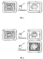
- FIG. 1 represents an image processing system in which an image processing effect is performed across all pixels.
- the image is displayed by first selecting a small number of representative colours, for example, 100 colours. Such a set of colours is called a palette.
- the palette as well as possibly other palettes for other images, is loaded into a piece of hardware called a colour lookup table (CLUT).
- CLUT colour lookup table
- the image is mapped so that each pixel in the image is assigned a number pointing to one of the colours in the palette.
- the hardware "refreshes" the image, typically 60 times a second, by retrieving for each pixel the mapped number, sending to the CLUT this number and receiving the exact colour to display for that pixel from the CLUT.
- the user constructs a "mask” that covers the image, protecting some image areas (the “masked” areas), while other areas are left exposed to the effect (the “unmasked” areas).
- the "masked”, “transition” and “unmasked” areas make up the mask, each of which is at a different mask state. For advanced effects, there may be more than one transition area.
- FIG. 2 illustrates the preferred embodiment of the present invention by showing a "masked" area protected from an imaging effect and a "unmasked” area subject to the image processing effect, where a fuzzy transition area separates the masked and unmasked areas.
- the image to the left is the initial image.
- the top right image illustrates a case where the face of the portrait corresponds to the masked area and the border has been brightened.
- the bottom right image illustrates the case where the background corresponds to the masked area and the face of the portrait has been brightened.
- the mask has a fuzzy transition area so a cut-out effect is avoided.
- Most edges in images are surprisingly soft under magnification. Defining a sharp boundary, even for edges that appear sharp, results in an image that appears to be cut out with scissors and pasted to the background. Further, even for a perfectly sharp boundary, a sharp mask will be displayed with staircased sides. The applicant has found that it is actually much better for the mask edge to be less sharp than the edge in the image being traced. The eye is much more forgiving of the high frequency edge detail being slightly muted than for unnatural edge detail being added. Even when the mask is slightly blurred with respect to the image boundary, the effect appears natural and the eye is unable to detect the presence of a mask. A sharp mask, on the other hand, almost always looks fake.
- the mask sharpness may vary as an edge falls in and out of focus, and, in the case of a face, may have a definable edge on the top, but a region of transition across the neck.
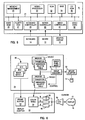
- FIG. 4 depicts a personal computer 10, preferably one in the IBM Ultimedia PS/2 series of computers, for example, the IBM PS/2 Ultimedia Model M57 SLC comprising a system unit 11, a keyboard 12, a mouse 13 and a display 14.
- the screen 16 of display device 14 is used to present the image during an image processing session.
- FIG. 5 shows a block diagram of the components of the computer shown in FIG. 4.
- the system unit 11 includes a system bus 21 to which various components are coupled and by which communication between the various components is accomplished.
- a microprocessor 22 is connected to the system bus 21 and is supported by read only memory (ROM) 23 and random access memory (RAM) (24) also connected to system bus 21.
- the microprocessor can be one of the Intel family of microprocessors including the 8088, 286, 386 or 486 or 586 microprocessors.
- the microprocessor in the IBM Ultimedia Model M57 SLC is the 386SLC processor which is a high performance cached version of the standard 386.
- microprocessors including, but not limited to, Motorola's family of microprocessors such as the 68000, 68020 or the 68030 microprocessors and various Reduced Instruction Set Computer (RISC) microprocessors manufactured by IBM, Hewlett Packard, Sun, Motorola and others may be used in the specific computer.
- RISC Reduced Instruction Set Computer
- the ROM 23 contains among other code the Basic Input/Output System (BIOS) which controls basic hardware operations such as the interactions of the disk drives and the keyboard.
- BIOS Basic Input/Output System
- the RAM 24 is the main memory into which the operating system and multimedia application programs are loaded.
- the memory management chip 25 is connected to the system bus 21 and controls direct memory access operations including, passing data between the RAM 24 and a hard disk drive 21 and floppy disk drive 27.
- a CD ROM 28, also coupled to the system bus 21, is used to store the large amount of data present in a multimedia program or presentation.
- the keyboard controller provides the hardware interface for the keyboard 12
- the mouse controller 30 provides the hardware interface for mouse 13
- the video controller 31 is the hardware interface for the display 14.
- a video card 32 such as the DVITM digital capture/display card may also be coupled to the system bus to provide image capture and display functions.
- the personal computer includes RAM 24 in which image manager 40, initial colour palette tables 42, processed colour palette tables 44 and image data 46 are stored.
- Image manager 40 includes colour mapping code to build the initial colour palette tables 42 from image data 46.
- the image manager 40 also contains user interface code to define the general boundaries of the three areas of the image, error diffusion code to map the image pixel by pixel to the three areas, and image processing code to process the initial colour palette tables 42 to the processed colour palette tables 44 according to the desired image processing effect. Once the processed colour palettes are built, the image manager 40 will transfer those palettes to the colour lookup table (CLUT) 50 in the video control display adapter 30 for presentation by the display 14.
- CLUT colour lookup table
- the personal computer processor 22 under control of the image manager 40 also builds data for a frame buffer 52 within the video controller 30.
- the frame buffer 52 contains the digital representation of the image to be displayed on the graphic display 14.
- Each pixel in the frame buffer 52 carries an index to a colour in the CLUT 50.
- red, green and blue intensities are passed to the red, blue, green drivers 56 that drive the three colour guns in the graphic display 14.
- the palette colours are chosen to be colours similar to those in the image.
- Most palettes contain no more than 256 colours so that each colour can be assigned a number within an 8-bit data string.
- the image is then mapped to the palette by assigning each pixel in the image a number which points to the closest colour in the palette. Error diffusion and other methods dither the assigned colours so that from a distance the displayed image has the appearance of continued shading, despite being composed of only relatively few colours.
- the graphic display has three colour guns, red, green and blue, to generate the colour from the screen and each storage location in the colour tables 42, 44, and 50 contains 24 bits, an 8-bit byte for each of the primary colours, red, green and blue. Therefore, each primary colour has 2 8 or 256 variations in shade from no intensity at 0 to brightest red, green or blue at 255. Since there are 2 8 intensities for each primary colour and there are three primary colours, the possible colour combinations are 2 24 . However, only 256 of these possible colour choices are typically loaded in the display colour table 50 by the image manager program 40.
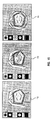
- FIG. 7 depicts a mask 60 associated with an image of a portrait.
- the mask is divided into three areas, unmasked area 61, transition area 62, and masked area 64. Since most typical palletized display adapters allow only 8 bits to be stored for each image pixel only 256 colours can be loaded in the colour lookup table.
- the preferred embodiment of the present invention divides these colours between separate palettes for each of the regions under the mask, three in this example. If the palettes are evenly divided, there can be 85 colours in the palette for each area. In this embodiment, the colour palette for the unmasked area 65, that for the intermediate area 67, and the masked area 69 each have 85 colours.
- step 100 in FIG. 10 where the artist has yet to decide that a masked image effect is desired, the system needs to know how many states the fuzzy mask will have in step 102 (FIG. 10). While the examples which follow illustrate a 3 state mask, other numbers of mask states are possible. The number of mask states influences the graininess of the image map and the graininess of the mask map in the transition region. An image with many colours in which the anticipated effect under the mask will be small could possibly use just two mask states. If the effect under the mask is extreme and the transition region large, 4 or even more mask states may be appropriate. The 3 mask states illustrated in the specification are adequate for a large number of images. The number of colour tables 42 allocated for the palettes is equal to the number of mask states.
- the total number of available palette colours are divided by the number of masking states, step 104. Assuming a 256 colour palette and 3 mask states, there will be 85 colours available per state.
- the three display palettes are defined by replicating the 85 colour palette 3 times giving 255 total colours.
- the display image is created by first mapping the entire image to 85 colours, step 105. There are many well known algorithms to perform the colour mapping; a particularly preferred technique is described below.
- the image pixels in the mapped image are given a number corresponding to the colour palette, adding an offset of 85N, where N is the integer level of the corresponding pixel in the mapped mask, N being 0, 1 or 2 in our example.
- the palettes are loaded into colour palette tables 42A, 42B and 42C in FIG. 8, and the image displayed using the 85 colour palette, step 106.
- FIGs. 14 and 15 below illustrate sample user interfaces to define a mask.
- a predefined mask can be selected from iconic means in a user interface.
- the predefined masks could include several masks analogous to the common masks used in modern day photography such as a center mask or vignetter, or a graduated effect common in special effect photographic filters. Or the user may define the mask in a customized manner for each image.
- each pixel in the transition area would contain a number expressing the magnitude of the mask effect for that pixel.
- the mapped mask information is stored in the mask definition table 43 (FIG.
- the value for all pixels is mapped to a small number of states, 0% or 0, 50% or 128, or 100% or 255 in the example. It is only during the much slower but much accurate development process described that the full range of values in the transition area are used.
- the monochrome mask image is now mapped to the number of states which in this example is three, step 110.
- the mapping preferably uses a good error diffusion technique to switch the mask pixels between mask areas. Dithering is an alternate mapping technique which could be used but is less preferred. Since colour is not involved, mapping the mask can be performed much quicker than mapping an image in which colour selections would be required.
- the resulting pixels which are allocated to the masked area are illustrated in white, those allocated to the transition area in gray, and those allocated to the unmasked area by black in FIG. 9.
- the diffusion allows the effect of the mask over an area to appear to vary continuously with position, even though only three states are available to the mask.
- the gray scale mask information is stored in the mask definition tables 43 (FIG. 8).
- any image such as a mask mapped to only 2 or 3 states is too grainy. This would be true if the mask were displayed on an image defining a transition from white to black, but in practice the difference in colour caused by the mask is not white to black, but is totally dependent on the magnitude of the image processing effect, and is typically not over 10%.
- a 10% brightness change across a 3 mask state is equivalent to 20 steps between pure white and pure black. It can be compared to a 20 3 , or 8000 state colour palette as a colour palette must cover three dimensions. While the 3 state mask is not quite as good as an 8000 colour palette covering the full image, it is at least a match for the 85 colour palette when the image effect is moderate.
- the original image appears on the screen.
- the image is composed of three palettes, each of the palettes is initially identical, so the image appears exactly like the underlying 85 colour mapped image, and there is no visible clue that there is a mask over the image.
- the image processing effect is applied to the palette colours in the unmasked area and half of the effect to the palette colours belonging to the transition region in step 112
- the image is altered and displayed next time the screen is refreshed step 114.
- the effect is applied only to 170 (85+85) palette colours, the calculation is performed 2,000 times faster than if the effect were applied to each of the 300,000 colour pixels in a typical full image. This speed enables the image to be adjusted by "feel", rather than relying on a delayed numerical approach as described above.
- each image pixel of the original unmapped image is retrieved from memory.
- the colour of this pixel is processed by the same image processing effect that was applied to each of the palette colours.
- the magnitude of this effect is multiplied by the unmapped mask pixel value for the effect which varies between 0 and 100%. Recall that in the display process described above, only 0%, 50% and 100% values for the image effect were used.
- the new image pixel values are combined and stored in memory as the developed image. Since the developed image uses the unmapped image and mask, it is free of the graininess which might be caused by the mapping. Development is much slower, however, than the simulation of the effect by changing only the palette according to the present invention.
- a new mask may be defined by reusing the original mapped image with the new mask,providing the image was not redeveloped. If the image was developed, the image must be remapped when a new mask is applied.
- FIGS. 11, 12 and 13 A second embodiment of the present invention which provides better image quality during palette adjustment at the expense of a slower setup time for a new mask is disclosed with reference to FIGS. 11, 12 and 13.
- step 150 the image is divided into three areas, step 152.
- the masked area 61, the unmasked area 64 and the transition area 62 are matched to the grey scale image, step 152.
- the pixels in the mask are mapped using the error diffusion technique as above, step 156.
- the second embodiment allocates the size of the palettes belonging to the three areas, step 154.
- Each region typically has a different mix of colours in the image and varies in importance due to size. There is no constraint that the regions use the same colours or the same number of colours; a better palette match is possible than with the first method in which the same palette was used for all three regions.
- the palettes for the three areas are chosen after the monochrome mask pixels have been mapped, step 160.
- the palette for the masked area is selected for all image pixels which correspond to a "masked" mask pixel in the mapped mask, for example, the black pixels in FIG. 9. Thus, some of the pixels used for selecting the palette for the masked area are in the transition area.
- the palette for the unmasked area is selected for the image pixels which correspond to an "unmasked" mask pixel in the mapped mask, the white pixels in FIG. 9.
- the palette for the transition area is selected for the image pixels which correspond to transition pixels in the mapped mask, the gray pixels in FIG.9. This is so that the colour palettes have the necessary colours to map the pixels.
- the colour mapping for the new palettes is accomplished using the same colour mapping routine as used in the first method.
- an image pixel corresponding to an unmasked mask pixel in the mapped mask must have a colour chosen from the unmasked colour palette; if an image pixel corresponds to a transition mask pixel in the mapped mask, the colour must be selected from the transition palette; and, if the image pixel corresponds to a masked mask pixel in the mapped mask, the colour must be selected from the mask palette.
- the image effect is applied to the unmasked palette and a partial image effect is applied to the transition palette, step 162.
- the altered image is displayed on the next screen refresh, step 164.
- the image cannot be mapped three times with the three palettes and a pixel chosen afterwards by the mask mapped pixels from those three images as in the first example, because in this case, that would disable the effect of the error diffusion by switching across three uncorrelated images, thereby causing excess grain.
- the mapping must be integrated into a single pass with palette selection controlled on a per pixel basis by the mapped mask image for diffusion to work, and the image must be remapped each time the mask is changed.
- Error diffusion is a method for minimizing conversion quantization error over multiple samples by eliminating the net average error.
- the value of the quantization error is conveyed to the next successive temporal or spatial quantization measurement as a negative feedback value.
- the quantization error attributed to the pixel at location (X, Y) on the video image is added as a positive feedback value during the quantization of data for the pixel at location (X+1, Y+1).
- the positive error feedback value so introduced is offset by the addition of complimentary error data during the quantization of the pixels at locations (X, Y+1) and (X+1, Y).
- the method reduces the noise level at the lower frequencies in the spatial spectrum where human visual acuity tends to be greatest.
- the preferred mode for the present invention is an improvement of the procedure disclosed in IBM Technical Disclosure Bulletin, Vol. 29, No. 3, August 1986, pp. 1329-34, entitled "Procedure for Optimum Choice of A Small Number of Colours From A Large Colour Palette for Colour Imaging” by G. W. Braudaway.
- the Braudaway algorithm uses two three-dimensional arrays with red, green and blue dimensions. The first "population” array holds a three-dimensional bar graph of the number of occurrences in the image of each colour, and the second "representational" array holds a measure of how well represented each colour is by the colours already chosen for the palette.
- the colours are chosen in the order in which the ratio of population to representation is highest. After each choice, the representation array is modified and the process is repeated until the palette is filled. After the selection of a colour, the Braudaway algorithm multiples each element in the representation array by the square of the Cartesian distance between that element's associated colour and the newly selected colour.
- the improved method changes the recalculation of the representation array by calculating the distance between the element's associated colour and the newly selected colour emphasizing luminance over chrominance after the distance is calculated.
- the distance in each element is multiplied by the fourth power of the distance.
- the representation array element is chosen to be the smaller of the original value or the original value multiplied by the fourth power of the distance.
- the fourth power is used as the colour formation and real world images are predominantly grouped in planar distributions within a colour cube. Let's assume that there are two planar regions in colour space, the first with one colour from the image per unit area and the second equal size region with n colours of the image per unit colour area. One unit of palette colours are available to satisfy both regions. X units of these colours will be allocated to region 1, leaving 1 - X units for region 2. With X colours to map the two-dimensional area of region 1, the X palette colours are laid as a square root of X by square root of X grid and the separation between the palette colours is proportional to 1 over the square root of X. The error or average distance from an arbitrary colour to the closest colour is also proportional to 1 over the square root of X.
- the error is proportional to 1 over the square root of (1 - X).
- the colours are distributed between the regions to minimize the mean squared error.
- the average error for each region is squared, multiplied by the number of colours in the region.
- the allocation variable, X is chosen to minimize some of the errors in the two regions.
- the visual noise is minimized when the ratio of the colours allocated between the areas is the square root of the ratio of the actual image colours contained in each region.
- D 2 (dR) 2 + (dG) 2 + (dB) 2
- D 2 K Y (dY) 2 + K D (dY) 2 + K Q (dQ) 2
- FIG. 14 is an illustration of one preferred embodiment of a user interface to define a customized mask.
- a series of "yin and yang" points are defined by using the mouse as a pick.
- the yin points are illustrated as white circles and denote an outside of the masked area and the yang points are illustrated as black circles which provide the inside of the unmasked area.
- Between the yin and yang points are one or more transition areas.
- the mouse can pick a yin point up by bringing the mouse cursor to the yin point, pressing and holding a mouse button to drag the yin point to a particular pixel in the drawing, then releasing the mouse button to relocate the point.
- a similar operation is performed for the yang points once the points are defined, the computer can interpolate the remainder of the mask using these points as reference. It is assumed at this point that the user has already selected the number of states in the mask.
- FIG. 15 illustrates another user interface which might be used with the present invention in which a plurality of predefined masks are available to the user; these predefined masks are represented as icons in the left column of the user interface. If the user clicks on a particular icon, a predefined mask will then appear at a predefined size and location on the screen. A circular mask is displayed over the image in the center illustration representing the boundaries of the masked, transisition and unmasked areas. If the mask is not sized or located correctly, the borders in the mask can be grabbed as a conventional window and dragged in order to situate and size the mask as desired. The mask has been resized larger and repositioned as shown in the right illustration of Figure 15.
- the masked area does not receive the selected image effect, it may if desired receive a complementary or opposite image effect. If the overall luminance level of the display is to remain constant and an artist increases the brightness of the unmasked area, the brightness of the masked area may be decreased if desired.
- the above described techniques of the preferred embodiment have the advantage that they provide nearly instantaneous feedback to the user after an effect is applied under control of a mask. Further, they avoid a cut-out appearance between the area which received the image processing operation and the area which was protected by the mask.
Description
- This invention relates generally to image processing. More particularly, it relates to techniques for performing image enhancement processing on portions of images.
- In image processing, frequently an image will be too dark, too red, too green or have some other defect which will require an image processing operation to be uniformly applied over the entire image. Also frequently, however, only one portion of the image will require a particular image processing effect. For example, a user, or shall we say an artist, might want to increase the red in the center of a portrait to enhance the skin tones, but leave the edges or back ground untouched. To create an effect in only one portion of an image, it is known to define a mask area to block a portion of the image from the chosen image processing operation.
- Heretofore, the known imaging applications and devices have shared one or both of the following defects for masked imaging operations:
- (i) a significant delay after the user has input the type and extent of the desired imaging effect; and/or
- (ii) a sharp line separating the masked and unmasked areas of the image.
- Colour enhancement in image processing is inherently a "right brained", creative activity. That is, the decision that more red is required in a specific area of an image is an aesthetic and artistic decision. Yet image processing with a data processing system relies on numeric quantization of the effect, forcing the artist into a left-brained approach, to achieve the desired changes. Image systems ask the artist to express desires as "fifty percent magenta" or "ten percent more contrast". Changing an image according to numerical calculations is hardly intuitive to a user and makes it difficult to optimize the image. This is particularly true if the user is inexperienced. Compounding this problem, is the fact that many image processing systems require a long delay while the processor calculates how to display the result of the image processing effect on the image.
- An expert able to work effectively with the delayed system has through experience constructed a mental model which gives instantaneous mental feedback. Such an expert can visualize what more magenta will do to a picture before going into a darkroom. However, such a model requires training and limits the number of variables the artist can handle. Even then multiple iterations are often required for accuracy. For a non-expert who has not developed this mental model, useful image processing colour enhancement can only be done with instantaneous feedback. Instantaneous feedback makes everyone an instant expert and adds excitement and immediacy to the process.
- Many image processing systems which use a masking effect leave a sharp line between the area where the image processing effect was carried out and that area which was masked. This is unacceptable as most edges in an image are surprisingly diffused under magnification. To avoid a cut-out appearance around the changed area, the mask must have a fuzzy or diffused edge.
- JP-A-1,081,152 describes a technique which uses two separate look-up tables, one for a specified area of an image, and the other for the remaining area of the image. By such an approach, colour changes can be made to the specified area by changing the colour information in the associated look-up table.
- EP-A-0,089,174 describes a video retouching system which uses a mask having mask pixels which are in one-to-one correspondence with the pixels of the image. It also identifies the problem that sharp edges tend to be formed when masks are used.
- To make an image enhancement system for the widest possible market, it should preferably combine a fuzzy mask with instantaneous feedback for the imaging effect. The prior art could give only one or the other. It is hence an object of the present invention to provide a system and method for improving an image processing operation carried out on a masked image by decreasing the feedback time of the processed image to the user, and eliminating the cut-out appearance of the processed image.
- Viewed from a first aspect, the present invention provides a method of altering an image by applying an image effect to a portion of the image, the method comprising the steps of associating a colour palette with that portion of the image, and altering that colour palette to apply the image effect to the portion of the image, the method being characterised by the steps of: (a) defining a mask comprising an array of mask pixels, each mask pixel corresponding to an image pixel in the image; (b) mapping the mask to produce a mapped mask in which each mask pixel is assigned to one of at least three mask areas, the at least three mask areas comprising a masked area, an unmasked area and a transition area, each mask pixel being assigned a state according to the mask area in which it lies; (c) assigning first, second and third colour palettes to the unmasked, masked and transition areas respectively; (d) applying the image effect to the first palette and partially applying the image effect to the third palette in order to produce altered first and third palettes; and (e) displaying the image wherein colours for image pixels corresponding to mask pixels of the masked, unmasked, and transition areas are chosen from the second, altered first, and altered third palettes respectively.
- Viewed from a second aspect, the present invention provides a data processing system for altering an image by applying an image effect to a portion of the image, the system comprising generation means for associating a colour palette with that portion of the image, and adjustment means for altering that colour palette to apply the image effect to the portion of the image, the system being characterised by: construction means for defining a mask comprising an array of mask pixels, each mask pixel corresponding to an image pixel in the image; mapping means for mapping the mask to produce a mapped mask in which each mask pixel is assigned to one of at least three mask areas, the at least three mask areas comprising a masked area, an unmasked area and a transition area, each mask pixel being assigned a state according to the mask area in which it lies; the generation means being arranged to assign first, second and third colour palettes to the unmasked, masked and transition areas respectively; the adjustment means being arranged to apply the image effect to the first palette and to partially apply the image effect to the third palette in order to produce altered first and third palettes; and display means for displaying the image wherein colours for image pixels corresponding to mask pixels of the masked, unmasked, and transition areas are chosen from the second, altered first, and altered third palettes respectively.
- The invention defines a mask having at least two areas, and then preferably maps the mask pixels with an error diffusion or dithering process. Image pixels which correspond in position to the mask pixels are then colour mapped to colour palettes selected for the two areas.
- In effect the image is divided up into two or preferably three different areas. First, in preferred embodiments the three different mask areas are defined on the image: the "masked" area where the selected image effect will not take place, the "unmasked" area where the selected image process will take place, and a transition area between the masked and unmasked areas where a partial version of the image process will take place. Three different colour palettes each of which correspond to one of the mask areas are chosen during colour mapping. After the general boundaries of the three areas are defined, then preferably an error diffusion or dithering algorithm based on the three states of the mask is performed to reassign mask pixels of the three areas so that a fuzzy or diffuse effect is achieved between the masked and unmasked areas. The colour image is mapped to the appropriate palette depending on the location of the image pixel.
- Typically the selected image processing operation will be performed on the palette corresponding to the unmasked area, no image operation be will performed on the palette corresponding to the masked area, and a partial effect is performed on the transition region palette.
- In one preferred embodiment, as there are 256 palette colours available in the display table in many computer systems, 85 colours are allocated to the palettes of the masked, unmasked and transition areas. Initially the 85 colours in each palette may be the same. Once the selected image operation is performed on the palettes of the unmasked and transition areas, the colours in the palettes of the three areas will be different. These palettes will be loaded into the colour display table of the display adapter of the computer system for presentation.
- The present invention will be described further, by way of example only, with reference to an embodiment thereof as illustrated in the accompanying drawings, in which:
- FIG. 1 depicts an image in which a image processing operation has been applied over the entire image;
- FIG. 2 depicts a mask operation in which a image operation is performed over part of the image;
- FIG. 3 is a representation produced according to the preferred embodiment of the present invention where an effect is applied over part of an image using a highly diffuse mask giving instantaneous feedback and avoiding the cut-out appearance of the prior art;
- FIG. 4 is a representation of a computer system in which image processing is performed including a system unit, a keyboard, a mouse and a display;
- FIG. 5 is a block diagram of the components of computer system shown in FIG. 4;
- FIG. 6 illustrates the preferred embodiment of the invention as implemented in the personal computer system;
- FIG. 7 is an illustration of a mask registered to an image, the mask having a masked area, a transition area and an unmasked area;
- FIG. 8 is a block diagram showing the image in a first embodiment of the present invention;
- FIG. 9 is an illustration of the error diffusion of the three mask areas showing that the mask pixels have switched between mask areas;
- FIG. 10 is a flow chart of the first embodiment of the invention;
- FIG. 11 shows a second embodiment of the invention illustrating a mask having a masked area, a transition area and an unmasked area;
- FIG. 12 is a block diagram showing the image in the second embodiment of the invention;
- FIG. 13 is a flow chart of the second embodiment of the invention;
- FIG. 14 is an illustration of a user interface for the masking operation; and
- FIG. 15 is an illustration of a user interface in which predetermined masks are available for user selection.
- FIG. 1 represents an image processing system in which an image processing effect is performed across all pixels. The image is displayed by first selecting a small number of representative colours, for example, 100 colours. Such a set of colours is called a palette. The palette, as well as possibly other palettes for other images, is loaded into a piece of hardware called a colour lookup table (CLUT). Next, the image is mapped so that each pixel in the image is assigned a number pointing to one of the colours in the palette. During display, the hardware "refreshes" the image, typically 60 times a second, by retrieving for each pixel the mapped number, sending to the CLUT this number and receiving the exact colour to display for that pixel from the CLUT. It is fairly easy to achieve near instantaneous feedback to the user when all pixels are subject to a particular image effect by modifying relatively small number of colours in the single palette and the associated CLUT. As illustrated, the right (processed) image is considerably brighter than the left initial image to illustrate a user controlling image brightness. When the computer senses a command to lighten the image, it adds a constant to all 100 colours in the palette and loads the revised palette in the CLUT. As the image is refreshed from
memory 60 times a second by the display adapter with the new values for each of the colours in the palette all 300,000 pixels on the screen change virtually instantaneously. - While some corrections can be done by changing the entire image, frequently, an effect must be limited to certain areas, perhaps the background needs darkening, or the eyes need to be a bit brighter. In such case, the user constructs a "mask" that covers the image, protecting some image areas (the "masked" areas), while other areas are left exposed to the effect (the "unmasked" areas). In the preferred embodiment, the "masked", "transition" and "unmasked" areas make up the mask, each of which is at a different mask state. For advanced effects, there may be more than one transition area.
- FIG. 2 illustrates the preferred embodiment of the present invention by showing a "masked" area protected from an imaging effect and a "unmasked" area subject to the image processing effect, where a fuzzy transition area separates the masked and unmasked areas. As above, the image to the left is the initial image. The top right image illustrates a case where the face of the portrait corresponds to the masked area and the border has been brightened. The bottom right image illustrates the case where the background corresponds to the masked area and the face of the portrait has been brightened.
- The mask has a fuzzy transition area so a cut-out effect is avoided. Most edges in images are surprisingly soft under magnification. Defining a sharp boundary, even for edges that appear sharp, results in an image that appears to be cut out with scissors and pasted to the background. Further, even for a perfectly sharp boundary, a sharp mask will be displayed with staircased sides. The applicant has found that it is actually much better for the mask edge to be less sharp than the edge in the image being traced. The eye is much more forgiving of the high frequency edge detail being slightly muted than for unnatural edge detail being added. Even when the mask is slightly blurred with respect to the image boundary, the effect appears natural and the eye is unable to detect the presence of a mask. A sharp mask, on the other hand, almost always looks fake. In the preferred embodiment of the present invention, the mask sharpness may vary as an edge falls in and out of focus, and, in the case of a face, may have a definable edge on the top, but a region of transition across the neck.
- Often there may be no definable edge at all to the mask and the artist wants to feather an area between the masked area and the area subject to the image processing effect. Such a case is illustrated in FIG. 3 in which the background is vignetted for a spotlight effect around the portrait. In this case, the transition region covers a large part of the image not necessarily following any boundary. To enable right brained artistic behavior and enable instant expertise the invention displays the change in the image more or less instantly to let the artist experiment with magnitude. Prior art packages which make an instantaneous effect available only let the user define a sharp mask.
- FIG. 4 depicts a
personal computer 10, preferably one in the IBM Ultimedia PS/2 series of computers, for example, the IBM PS/2 Ultimedia Model M57 SLC comprising asystem unit 11, akeyboard 12, amouse 13 and adisplay 14. Thescreen 16 ofdisplay device 14 is used to present the image during an image processing session. - FIG. 5 shows a block diagram of the components of the computer shown in FIG. 4. The
system unit 11 includes asystem bus 21 to which various components are coupled and by which communication between the various components is accomplished. Amicroprocessor 22 is connected to thesystem bus 21 and is supported by read only memory (ROM) 23 and random access memory (RAM) (24) also connected tosystem bus 21. The microprocessor can be one of the Intel family of microprocessors including the 8088, 286, 386 or 486 or 586 microprocessors. The microprocessor in the IBM Ultimedia Model M57 SLC is the 386SLC processor which is a high performance cached version of the standard 386. However, other microprocessors including, but not limited to, Motorola's family of microprocessors such as the 68000, 68020 or the 68030 microprocessors and various Reduced Instruction Set Computer (RISC) microprocessors manufactured by IBM, Hewlett Packard, Sun, Motorola and others may be used in the specific computer. - The
ROM 23 contains among other code the Basic Input/Output System (BIOS) which controls basic hardware operations such as the interactions of the disk drives and the keyboard. TheRAM 24 is the main memory into which the operating system and multimedia application programs are loaded. Thememory management chip 25 is connected to thesystem bus 21 and controls direct memory access operations including, passing data between theRAM 24 and ahard disk drive 21 andfloppy disk drive 27. ACD ROM 28, also coupled to thesystem bus 21, is used to store the large amount of data present in a multimedia program or presentation. - Also connected to this
system bus 21 are three I/O controllers: thekeyboard controller 29, themouse controller 30 and thevideo controller 31. As might be expected, the keyboard controller provides the hardware interface for thekeyboard 12, themouse controller 30 provides the hardware interface formouse 13 and thevideo controller 31 is the hardware interface for thedisplay 14. Lastly, avideo card 32 such as the DVI™ digital capture/display card may also be coupled to the system bus to provide image capture and display functions. - In FIG. 6, the personal computer includes
RAM 24 in whichimage manager 40, initial colour palette tables 42, processed colour palette tables 44 andimage data 46 are stored.Image manager 40 includes colour mapping code to build the initial colour palette tables 42 fromimage data 46. Theimage manager 40 also contains user interface code to define the general boundaries of the three areas of the image, error diffusion code to map the image pixel by pixel to the three areas, and image processing code to process the initial colour palette tables 42 to the processed colour palette tables 44 according to the desired image processing effect. Once the processed colour palettes are built, theimage manager 40 will transfer those palettes to the colour lookup table (CLUT) 50 in the videocontrol display adapter 30 for presentation by thedisplay 14. - The personal computer processor 22 (FIG. 5) under control of the
image manager 40 also builds data for aframe buffer 52 within thevideo controller 30. Theframe buffer 52 contains the digital representation of the image to be displayed on thegraphic display 14. Each pixel in theframe buffer 52 carries an index to a colour in theCLUT 50. When a pixel is to be displayed, its red, green and blue intensities are passed to the red, blue,green drivers 56 that drive the three colour guns in thegraphic display 14. - Typically, the palette colours are chosen to be colours similar to those in the image. Most palettes contain no more than 256 colours so that each colour can be assigned a number within an 8-bit data string. The image is then mapped to the palette by assigning each pixel in the image a number which points to the closest colour in the palette. Error diffusion and other methods dither the assigned colours so that from a distance the displayed image has the appearance of continued shading, despite being composed of only relatively few colours.
- The graphic display has three colour guns, red, green and blue, to generate the colour from the screen and each storage location in the colour tables 42, 44, and 50 contains 24 bits, an 8-bit byte for each of the primary colours, red, green and blue. Therefore, each primary colour has 28 or 256 variations in shade from no intensity at 0 to brightest red, green or blue at 255. Since there are 28 intensities for each primary colour and there are three primary colours, the possible colour combinations are 224. However, only 256 of these possible colour choices are typically loaded in the display colour table 50 by the
image manager program 40. - FIG. 7 depicts a
mask 60 associated with an image of a portrait. The mask is divided into three areas, unmaskedarea 61,transition area 62, andmasked area 64. Since most typical palletized display adapters allow only 8 bits to be stored for each image pixel only 256 colours can be loaded in the colour lookup table. The preferred embodiment of the present invention divides these colours between separate palettes for each of the regions under the mask, three in this example. If the palettes are evenly divided, there can be 85 colours in the palette for each area. In this embodiment, the colour palette for the unmaskedarea 65, that for theintermediate area 67, and themasked area 69 each have 85 colours. - After the initial display of the image,
step 100 in FIG. 10 where the artist has yet to decide that a masked image effect is desired, the system needs to know how many states the fuzzy mask will have in step 102 (FIG. 10). While the examples which follow illustrate a 3 state mask, other numbers of mask states are possible. The number of mask states influences the graininess of the image map and the graininess of the mask map in the transition region. An image with many colours in which the anticipated effect under the mask will be small could possibly use just two mask states. If the effect under the mask is extreme and the transition region large, 4 or even more mask states may be appropriate. The 3 mask states illustrated in the specification are adequate for a large number of images. The number of colour tables 42 allocated for the palettes is equal to the number of mask states. - Next, the total number of available palette colours are divided by the number of masking states,
step 104. Assuming a 256 colour palette and 3 mask states, there will be 85 colours available per state. The three display palettes are defined by replicating the 85colour palette 3 times giving 255 total colours. The display image is created by first mapping the entire image to 85 colours,step 105. There are many well known algorithms to perform the colour mapping; a particularly preferred technique is described below. The image pixels in the mapped image are given a number corresponding to the colour palette, adding an offset of 85N, where N is the integer level of the corresponding pixel in the mapped mask, N being 0, 1 or 2 in our example. The palettes are loaded into colour palette tables 42A, 42B and 42C in FIG. 8, and the image displayed using the 85 colour palette,step 106. - Generating the mask is now explained. FIGs. 14 and 15 below illustrate sample user interfaces to define a mask. A predefined mask can be selected from iconic means in a user interface. The predefined masks could include several masks analogous to the common masks used in modern day photography such as a center mask or vignetter, or a graduated effect common in special effect photographic filters. Or the user may define the mask in a customized manner for each image.
- After the general dimensions of the mask are defined in
step 108, there is a masked area, an unmasked area exposed to the image processing effects and a transition region generally much smaller in extent than the masked area or the unmasked area and partially exposed to the imaging effect. Each pixel in the transition area would contain a number expressing the magnitude of the mask effect for that pixel. The mask has the form of a monochrome image. In one preferred embodiment, each pixel of the mask has an 8-bit value varying from 0=unmasked area and 255=masked area. A continuum of values between 1 and 254 define the transition region,step 109. The mapped mask information is stored in the mask definition table 43 (FIG. 8) For purposes of display of the instantaneous display of the fuzzy mask, the value for all pixels is mapped to a small number of states, 0% or 0, 50% or 128, or 100% or 255 in the example. It is only during the much slower but much accurate development process described that the full range of values in the transition area are used. - The monochrome mask image is now mapped to the number of states which in this example is three,
step 110. The mapping preferably uses a good error diffusion technique to switch the mask pixels between mask areas. Dithering is an alternate mapping technique which could be used but is less preferred. Since colour is not involved, mapping the mask can be performed much quicker than mapping an image in which colour selections would be required. As above, the resulting pixels which are allocated to the masked area are illustrated in white, those allocated to the transition area in gray, and those allocated to the unmasked area by black in FIG. 9. The diffusion allows the effect of the mask over an area to appear to vary continuously with position, even though only three states are available to the mask. The gray scale mask information is stored in the mask definition tables 43 (FIG. 8). - Conventional wisdom would suggest that any image such as a mask mapped to only 2 or 3 states is too grainy. This would be true if the mask were displayed on an image defining a transition from white to black, but in practice the difference in colour caused by the mask is not white to black, but is totally dependent on the magnitude of the image processing effect, and is typically not over 10%. A 10% brightness change across a 3 mask state is equivalent to 20 steps between pure white and pure black. It can be compared to a 203, or 8000 state colour palette as a colour palette must cover three dimensions. While the 3 state mask is not quite as good as an 8000 colour palette covering the full image, it is at least a match for the 85 colour palette when the image effect is moderate.
- When the image is displayed in
step 106, the original image appears on the screen. Even though the image is composed of three palettes, each of the palettes is initially identical, so the image appears exactly like the underlying 85 colour mapped image, and there is no visible clue that there is a mask over the image. By applying the image processing effect to the palette colours in the unmasked area and half of the effect to the palette colours belonging to the transition region instep 112, the image is altered and displayed next time the screen isrefreshed step 114. As the effect is applied only to 170 (85+85) palette colours, the calculation is performed 2,000 times faster than if the effect were applied to each of the 300,000 colour pixels in a typical full image. This speed enables the image to be adjusted by "feel", rather than relying on a delayed numerical approach as described above. - It will be apparent to the person skilled in the art that there exist many image processing techniques which might be applied to the unmasked and transition areas.
- After the magnitude of the effect has been evaluated and the optimum parameters are established by the artist, the effect is applied to each of the image pixels under the control of the full gray scale mask in a much slower procedure called development. In development, each image pixel of the original unmapped image is retrieved from memory. The colour of this pixel is processed by the same image processing effect that was applied to each of the palette colours. The magnitude of this effect is multiplied by the unmapped mask pixel value for the effect which varies between 0 and 100%. Recall that in the display process described above, only 0%, 50% and 100% values for the image effect were used. Finally, the new image pixel values are combined and stored in memory as the developed image. Since the developed image uses the unmapped image and mask, it is free of the graininess which might be caused by the mapping. Development is much slower, however, than the simulation of the effect by changing only the palette according to the present invention.
- One feature of the first embodiment of the invention is that a new mask may be defined by reusing the original mapped image with the new mask,providing the image was not redeveloped. If the image was developed, the image must be remapped when a new mask is applied.
- A second embodiment of the present invention which provides better image quality during palette adjustment at the expense of a slower setup time for a new mask is disclosed with reference to FIGS. 11, 12 and 13. The nearly instantaneous display of the effect of a given image processing operation, however, does not change.
- To practice the second method, as before, after the image is displayed,
step 150, the image is divided into three areas,step 152. Themasked area 61, the unmaskedarea 64 and thetransition area 62 are matched to the grey scale image,step 152. Next, the pixels in the mask are mapped using the error diffusion technique as above,step 156. - The second embodiment allocates the size of the palettes belonging to the three areas,
step 154. Each region typically has a different mix of colours in the image and varies in importance due to size. There is no constraint that the regions use the same colours or the same number of colours; a better palette match is possible than with the first method in which the same palette was used for all three regions. In the second embodiment, the palettes for the three areas are chosen after the monochrome mask pixels have been mapped,step 160. The palette for the masked area is selected for all image pixels which correspond to a "masked" mask pixel in the mapped mask, for example, the black pixels in FIG. 9. Thus, some of the pixels used for selecting the palette for the masked area are in the transition area. The palette for the unmasked area is selected for the image pixels which correspond to an "unmasked" mask pixel in the mapped mask, the white pixels in FIG. 9. The palette for the transition area is selected for the image pixels which correspond to transition pixels in the mapped mask, the gray pixels in FIG.9. This is so that the colour palettes have the necessary colours to map the pixels. - The colour mapping for the new palettes is accomplished using the same colour mapping routine as used in the first method. However, as there are three different palettes from which to select, an image pixel corresponding to an unmasked mask pixel in the mapped mask must have a colour chosen from the unmasked colour palette; if an image pixel corresponds to a transition mask pixel in the mapped mask, the colour must be selected from the transition palette; and, if the image pixel corresponds to a masked mask pixel in the mapped mask, the colour must be selected from the mask palette.
- Next, as in the first embodiment, the image effect is applied to the unmasked palette and a partial image effect is applied to the transition palette,
step 162. The altered image is displayed on the next screen refresh,step 164. - In the second method, the image cannot be mapped three times with the three palettes and a pixel chosen afterwards by the mask mapped pixels from those three images as in the first example, because in this case, that would disable the effect of the error diffusion by switching across three uncorrelated images, thereby causing excess grain. The mapping must be integrated into a single pass with palette selection controlled on a per pixel basis by the mapped mask image for diffusion to work, and the image must be remapped each time the mask is changed.
- While there exist many acceptable methods in the prior art for carrying out the error diffusion operation to map mask pixels to the three mask areas, a preferred embodiment uses that method described in copending European Patent Application No. 92304507.4, "Error Diffusion Signal Processing", filed on 19 May 1992. To match the quantitized image and the frequency characteristics of the human eye, the invention teaches the selective use of positive feedback as applied to the quantization error.
- Error diffusion is a method for minimizing conversion quantization error over multiple samples by eliminating the net average error. In conventional error diffusion, the value of the quantization error is conveyed to the next successive temporal or spatial quantization measurement as a negative feedback value.
- According to the copending European Application No 92304507.4, the quantization error attributed to the pixel at location (X, Y) on the video image is added as a positive feedback value during the quantization of data for the pixel at location (X+1, Y+1). The positive error feedback value so introduced is offset by the addition of complimentary error data during the quantization of the pixels at locations (X, Y+1) and (X+1, Y). The method reduces the noise level at the lower frequencies in the spatial spectrum where human visual acuity tends to be greatest.
- While there exist many methods for selecting a palette of colours customized for a selected image, the preferred mode for the present invention is an improvement of the procedure disclosed in IBM Technical Disclosure Bulletin, Vol. 29, No. 3, August 1986, pp. 1329-34, entitled "Procedure for Optimum Choice of A Small Number of Colours From A Large Colour Palette for Colour Imaging" by G. W. Braudaway. The Braudaway algorithm uses two three-dimensional arrays with red, green and blue dimensions. The first "population" array holds a three-dimensional bar graph of the number of occurrences in the image of each colour, and the second "representational" array holds a measure of how well represented each colour is by the colours already chosen for the palette. The colours are chosen in the order in which the ratio of population to representation is highest. After each choice, the representation array is modified and the process is repeated until the palette is filled. After the selection of a colour, the Braudaway algorithm multiples each element in the representation array by the square of the Cartesian distance between that element's associated colour and the newly selected colour.
- The improved method changes the recalculation of the representation array by calculating the distance between the element's associated colour and the newly selected colour emphasizing luminance over chrominance after the distance is calculated. In addition, rather than squaring the distance, the distance in each element is multiplied by the fourth power of the distance. The representation array element is chosen to be the smaller of the original value or the original value multiplied by the fourth power of the distance.
- The fourth power is used as the colour formation and real world images are predominantly grouped in planar distributions within a colour cube. Let's assume that there are two planar regions in colour space, the first with one colour from the image per unit area and the second equal size region with n colours of the image per unit colour area. One unit of palette colours are available to satisfy both regions. X units of these colours will be allocated to
region 1, leaving 1 - X units forregion 2. With X colours to map the two-dimensional area ofregion 1, the X palette colours are laid as a square root of X by square root of X grid and the separation between the palette colours is proportional to 1 over the square root of X. The error or average distance from an arbitrary colour to the closest colour is also proportional to 1 over the square root of X. Similarly, forregion 2, the error is proportional to 1 over the square root of (1 - X). To minimize visual noise, the colours are distributed between the regions to minimize the mean squared error. The average error for each region is squared, multiplied by the number of colours in the region. The allocation variable, X, is chosen to minimize some of the errors in the two regions. The visual noise is minimized when the ratio of the colours allocated between the areas is the square root of the ratio of the actual image colours contained in each region. - The eye is more sensitive to luminance rather than colour. Rather than calculating the distance in Cartesian space by the equation: D2= (dR)2+ (dG)2+ (dB)2, the following set of equations are used:


- (dR) =
- difference in red component of the two colours whose distance is being found.
- These formulas emphasize fine steps in luminance (to which the eye is most sensitive) over colour (to which the eye is less sensitive). The large area sensitivity of the eye to colour is served by the error diffusion used as the image pixels are assigned palette colours. It is interesting that to the extent colours are randomly chosen in a region of volume, the above directional emphasis will have no statistical effect just as a cube of air expanded horizontally is undistinguishable on a model scale from one expanded vertically, however, the treatment of non-random formations in colour space will be affected by the above formulas.
- FIG. 14 is an illustration of one preferred embodiment of a user interface to define a customized mask. In the portrait, a series of "yin and yang" points are defined by using the mouse as a pick. In this case, the yin points are illustrated as white circles and denote an outside of the masked area and the yang points are illustrated as black circles which provide the inside of the unmasked area. Between the yin and yang points are one or more transition areas. The mouse can pick a yin point up by bringing the mouse cursor to the yin point, pressing and holding a mouse button to drag the yin point to a particular pixel in the drawing, then releasing the mouse button to relocate the point. A similar operation is performed for the yang points once the points are defined, the computer can interpolate the remainder of the mask using these points as reference. It is assumed at this point that the user has already selected the number of states in the mask.
- FIG. 15 illustrates another user interface which might be used with the present invention in which a plurality of predefined masks are available to the user; these predefined masks are represented as icons in the left column of the user interface. If the user clicks on a particular icon, a predefined mask will then appear at a predefined size and location on the screen. A circular mask is displayed over the image in the center illustration representing the boundaries of the masked, transisition and unmasked areas. If the mask is not sized or located correctly, the borders in the mask can be grabbed as a conventional window and dragged in order to situate and size the mask as desired. The mask has been resized larger and repositioned as shown in the right illustration of Figure 15.
- It will be understood by those skilled in the art that modifications may be made to the above described embodiment without departing from the scope of the invention as defined in the appended claims. For example, while the masked area does not receive the selected image effect, it may if desired receive a complementary or opposite image effect. If the overall luminance level of the display is to remain constant and an artist increases the brightness of the unmasked area, the brightness of the masked area may be decreased if desired.
- The above described techniques of the preferred embodiment have the advantage that they provide nearly instantaneous feedback to the user after an effect is applied under control of a mask. Further, they avoid a cut-out appearance between the area which received the image processing operation and the area which was protected by the mask.
Claims (13)
- A method of altering an image by applying an image effect to a portion of the image, the method comprising the steps of associating a colour palette with that portion of the image, and altering that colour palette to apply the image effect to the portion of the image, the method being characterised by the steps of:(a) defining (108; 152) a mask (60) comprising an array of mask pixels, each mask pixel corresponding to an image pixel in the image;(b) mapping (110; 156) the mask to produce a mapped mask in which each mask pixel is assigned to one of at least three mask areas, the at least three mask areas comprising a masked area (64), an unmasked area (61) and a transition area (62), each mask pixel being assigned a state according to the mask area in which it lies;(c) assigning first (42A), second (42C) and third (42B) colour palettes to the unmasked (61), masked (64) and transition (62) areas respectively;(d) applying (112; 162) the image effect to the first palette (42A) and partially applying the image effect to the third palette (42B) in order to produce altered first (44A) and third (44B) palettes; and(e) displaying (114; 164) the image wherein colours for image pixels corresponding to mask pixels of the masked (64), unmasked (61), and transition (62) areas are chosen from the second (42C), altered first (44A), and altered third (44B) palettes respectively.
- A method as claimed in Claim 1, further comprising the steps of:matching (109; 154) mask pixels in the transition area (62) of the mask (60) to a continuous grey scale mask, the mask pixels being assigned a respective intensity value; anddeveloping the image by applying the image effect to image pixels corresponding to mask pixels in the unmasked area (61) of the mask (60), and applying the image effect multiplied by the respective mask pixel intensity value to image pixels corresponding to mask pixels in the transition area (62) of the mask (60).
- A method as claimed in Claim 1 or Claim 2, wherein, based on the mask pixel states associated with the palettes, it is determined at said step (d) for each palette to which the image effect is to be applied, whether the full image effect or a partial image effect should be applied to that palette.
- A method as claimed in any preceding claim wherein the mask mapping step is accomplished by error diffusion.
- A method as claimed in any of Claims 1 to 3 wherein the mask mapping step is accomplished by dithering.
- A method as claimed in any preceding claim wherein the palettes (42A, 42B, 42C) are generated at step (c) using image pixels which correspond in position to the mask pixels assigned to the associated mask area (61, 62, 64).
- A method as claimed in Claim 6 wherein the colours in the palettes (42A, 42B, 42C) are selected according to size and colour of those areas of the image comprising image pixels corresponding to mask pixels of the associated mask area (61, 62, 64).
- A method as claimed in any of Claims 1 to 5 wherein the palettes (42A, 42B, 42C) are selected before the mask mapping step (b).
- A method as claimed in Claim 8 wherein the palettes (42A, 42B, 42C) contain an identical set of colours.
- A data processing system for altering an image by applying an image effect to a portion of the image, the system comprising generation means for associating a colour palette with that portion of the image, and adjustment means for altering that colour palette to apply the image effect to the portion of the image, the system being characterised by:construction means for defining a mask (60) comprising an array of mask pixels, each mask pixel corresponding to an image pixel in the image;mapping means for mapping the mask to produce a mapped mask in which each mask pixel is assigned to one of at least three mask areas, the at least three mask areas comprising a masked area (64), an unmasked area (61) and a transition area (62), each mask pixel being assigned a state according to the mask area in which it lies;the generation means being arranged to assign first (42A), second (42C) and third (42B) colour palettes to the unmasked (61), masked (64) and transition (62) areas respectively;the adjustment means being arranged to apply the image effect to the first palette (42A) and to partially apply the image effect to the third palette (42B) in order to produce altered first (44A) and third (44B) palettes; anddisplay means for displaying the image wherein colours for image pixels corresponding to mask pixels of the masked (64), unmasked (61), and transition (62) areas are chosen from the second (42C), altered first (44A), and altered third (44B) palettes respectively.
- A system as claimed in Claim 10, further comprising:matching means to match mask pixels in the transition area (62) of the mask (60) to a continuous grey scale mask, the mask pixels being assigned a respective intensity value; anddevelopment means to develop the image by applying the image effect to image pixels corresponding to mask pixels in the unmasked area (61) of the mask (60), and applying the image effect multiplied by the respective mask pixel intensity value to image pixels corresponding to mask pixels in the transition area (62) of the mask (60).
- A system as claimed in Claim 10 or Claim 11, further comprising decision logic for determining, for each palette to which the image effect is to be applied, based on the mask pixel states associated with the palettes, whether the full image effect or a partial image effect should be applied to that palette.
- A system as claimed in any of Claims 10 to 12, wherein the palettes (42A, 42B, 42C) are generated using image pixels which correspond in position to the mask pixels assigned to the associated mask area (61, 62, 64).
Applications Claiming Priority (2)
| Application Number | Priority Date | Filing Date | Title |
|---|---|---|---|
| US925340 | 1992-08-04 | ||
| US07/925,340 US5319742A (en) | 1992-08-04 | 1992-08-04 | Image enhancement with mask having fuzzy edges |
Publications (2)
| Publication Number | Publication Date |
|---|---|
| EP0586082A1 EP0586082A1 (en) | 1994-03-09 |
| EP0586082B1 true EP0586082B1 (en) | 1997-05-02 |
Family
ID=25451581
Family Applications (1)
| Application Number | Title | Priority Date | Filing Date |
|---|---|---|---|
| EP93305944A Expired - Lifetime EP0586082B1 (en) | 1992-08-04 | 1993-07-27 | Palettized fuzzy mask |
Country Status (4)
| Country | Link |
|---|---|
| US (2) | US5319742A (en) |
| EP (1) | EP0586082B1 (en) |
| JP (1) | JP2675966B2 (en) |
| DE (1) | DE69310293T2 (en) |
Families Citing this family (42)
| Publication number | Priority date | Publication date | Assignee | Title |
|---|---|---|---|---|
| CA2093448C (en) * | 1992-07-17 | 1999-03-09 | Albert D. Edgar | Expert system for image enhancement |
| US5319742A (en) * | 1992-08-04 | 1994-06-07 | International Business Machines Corporation | Image enhancement with mask having fuzzy edges |
| US5612716A (en) * | 1992-08-24 | 1997-03-18 | Casio Computer Co., Ltd. | Image display device |
| NL9201761A (en) * | 1992-10-12 | 1994-05-02 | Oce Nederland Bv | Method for assigning a pertinent indication in relation to color behavior to a pixel to be displayed with a color display system, as well as a color display system arranged for carrying out such a method. |
| US5857038A (en) * | 1993-06-29 | 1999-01-05 | Canon Kabushiki Kaisha | Image processing apparatus and method for synthesizing first and second image data |
| US5808669A (en) * | 1995-02-07 | 1998-09-15 | Adaptive Optics Associates, Inc. | Telecine with dual digitizers and multiple scanning beams |
| CA2169902A1 (en) | 1995-03-16 | 1996-09-17 | Allan Chiwan Cheung | Combined color halftoning |
| US5701365A (en) * | 1996-06-21 | 1997-12-23 | Xerox Corporation | Subpixel character positioning with antialiasing with grey masking techniques |
| US5801710A (en) * | 1996-08-19 | 1998-09-01 | Eastman Kodak Company | Computer program product for defining a soft edge in a digital mask |
| JP3037161B2 (en) * | 1996-11-08 | 2000-04-24 | 日本電気アイシーマイコンシステム株式会社 | Graphic image display device and graphic image display method |
| US5960099A (en) * | 1997-02-25 | 1999-09-28 | Hayes, Jr.; Carl Douglas | System and method for creating a digitized likeness of persons |
| US6283858B1 (en) | 1997-02-25 | 2001-09-04 | Bgk International Incorporated | Method for manipulating images |
| US6191793B1 (en) | 1998-04-01 | 2001-02-20 | Real 3D, Inc. | Method and apparatus for texture level of detail dithering |
| US6333749B1 (en) | 1998-04-17 | 2001-12-25 | Adobe Systems, Inc. | Method and apparatus for image assisted modeling of three-dimensional scenes |
| US6281904B1 (en) * | 1998-06-09 | 2001-08-28 | Adobe Systems Incorporated | Multi-source texture reconstruction and fusion |
| US6189064B1 (en) | 1998-11-09 | 2001-02-13 | Broadcom Corporation | Graphics display system with unified memory architecture |
| US7982740B2 (en) | 1998-11-09 | 2011-07-19 | Broadcom Corporation | Low resolution graphics mode support using window descriptors |
| US6798420B1 (en) * | 1998-11-09 | 2004-09-28 | Broadcom Corporation | Video and graphics system with a single-port RAM |
| US6636222B1 (en) * | 1999-11-09 | 2003-10-21 | Broadcom Corporation | Video and graphics system with an MPEG video decoder for concurrent multi-row decoding |
| US6573905B1 (en) | 1999-11-09 | 2003-06-03 | Broadcom Corporation | Video and graphics system with parallel processing of graphics windows |
| US7446774B1 (en) | 1998-11-09 | 2008-11-04 | Broadcom Corporation | Video and graphics system with an integrated system bridge controller |
| US6853385B1 (en) | 1999-11-09 | 2005-02-08 | Broadcom Corporation | Video, audio and graphics decode, composite and display system |
| US6661422B1 (en) * | 1998-11-09 | 2003-12-09 | Broadcom Corporation | Video and graphics system with MPEG specific data transfer commands |
| US6768774B1 (en) | 1998-11-09 | 2004-07-27 | Broadcom Corporation | Video and graphics system with video scaling |
| AU742872B2 (en) * | 1998-12-24 | 2002-01-17 | Canon Kabushiki Kaisha | A method of blurring an image |
| US6606166B1 (en) * | 1999-04-30 | 2003-08-12 | Adobe Systems Incorporated | Pattern dithering |
| US6975324B1 (en) | 1999-11-09 | 2005-12-13 | Broadcom Corporation | Video and graphics system with a video transport processor |
| US7724270B1 (en) * | 2000-11-08 | 2010-05-25 | Palm, Inc. | Apparatus and methods to achieve a variable color pixel border on a negative mode screen with a passive matrix drive |
| US6952286B2 (en) * | 2000-12-07 | 2005-10-04 | Eastman Kodak Company | Doubleprint photofinishing service with the second print having subject content-based modifications |
| US6844882B1 (en) * | 2000-12-13 | 2005-01-18 | Adobe Systems Incorporated | Variable dithering for GIF |
| TWI220505B (en) * | 2001-08-13 | 2004-08-21 | Ulead Systems Inc | Image enhancement method |
| WO2003036558A1 (en) * | 2001-10-24 | 2003-05-01 | Nik Multimedia, Inc. | User definable image reference points |
| US7602991B2 (en) * | 2001-10-24 | 2009-10-13 | Nik Software, Inc. | User definable image reference regions |
| US8063916B2 (en) | 2003-10-22 | 2011-11-22 | Broadcom Corporation | Graphics layer reduction for video composition |
| US7869094B2 (en) * | 2005-01-07 | 2011-01-11 | Mitcham Global Investments Ltd. | Selective dithering |
| US7634152B2 (en) * | 2005-03-07 | 2009-12-15 | Hewlett-Packard Development Company, L.P. | System and method for correcting image vignetting |
| US20070150748A1 (en) * | 2005-12-23 | 2007-06-28 | Lee Hildebrand | Method of Generating an Artistic Expression Using Biometric Information |
| US8139083B2 (en) * | 2006-08-09 | 2012-03-20 | Sony Ericsson Mobile Communications Ab | Custom image frames |
| JP2008124803A (en) * | 2006-11-13 | 2008-05-29 | Omron Corp | Image processing apparatus and method |
| US8175409B1 (en) * | 2006-12-01 | 2012-05-08 | Adobe Systems Incorporated | Coherent image selection and modification |
| US8284212B2 (en) * | 2009-06-17 | 2012-10-09 | Echostar Technologies L.L.C. | Systems and methods for combining images into a file using multiple color palettes |
| JP5594282B2 (en) * | 2011-03-31 | 2014-09-24 | カシオ計算機株式会社 | Image processing device |
Family Cites Families (7)
| Publication number | Priority date | Publication date | Assignee | Title |
|---|---|---|---|---|
| US4617592A (en) * | 1982-03-11 | 1986-10-14 | Crosfield Electronics Limited | Video retouching system |
| US4878178A (en) * | 1985-12-25 | 1989-10-31 | Sharp Kabushiki Kaisha | Image processing device |
| JPS6481152A (en) * | 1987-09-21 | 1989-03-27 | Shimadzu Corp | Display device |
| US5031050A (en) * | 1990-02-26 | 1991-07-09 | Hewlett-Packard Company | Method and system for reproducing monochromatic and color images using ordered dither and error diffusion |
| FR2668276B1 (en) * | 1990-10-22 | 1992-12-31 | Elf Aquitaine | PROCESS FOR OPERATING COLORS ON SCREEN. |
| US5172247A (en) * | 1990-10-24 | 1992-12-15 | Eastman Kodak Company | High speed digital error diffusion process for continuous tone image-to-binary image conversion |
| US5319742A (en) * | 1992-08-04 | 1994-06-07 | International Business Machines Corporation | Image enhancement with mask having fuzzy edges |
-
1992
- 1992-08-04 US US07/925,340 patent/US5319742A/en not_active Expired - Lifetime
-
1993
- 1993-06-30 JP JP5160778A patent/JP2675966B2/en not_active Expired - Fee Related
- 1993-07-27 DE DE69310293T patent/DE69310293T2/en not_active Expired - Lifetime
- 1993-07-27 EP EP93305944A patent/EP0586082B1/en not_active Expired - Lifetime
-
1994
- 1994-01-24 US US08/185,636 patent/US5611027A/en not_active Expired - Lifetime
Also Published As
| Publication number | Publication date |
|---|---|
| JP2675966B2 (en) | 1997-11-12 |
| DE69310293D1 (en) | 1997-06-05 |
| JPH06111014A (en) | 1994-04-22 |
| US5611027A (en) | 1997-03-11 |
| US5319742A (en) | 1994-06-07 |
| EP0586082A1 (en) | 1994-03-09 |
| DE69310293T2 (en) | 1997-10-30 |
Similar Documents
| Publication | Publication Date | Title |
|---|---|---|
| EP0586082B1 (en) | Palettized fuzzy mask | |
| US5204665A (en) | Color editing with simple encoded images | |
| US5867169A (en) | Method and apparatus for manipulating color values in a computer graphics system | |
| CN105574918B (en) | A kind of material adding method, device and the terminal of 3D models | |
| US5138303A (en) | Method and apparatus for displaying color on a computer output device using dithering techniques | |
| US5179641A (en) | Rendering shaded areas with boundary-localized pseudo-random noise | |
| KR101076900B1 (en) | System and method for displaying images utilizing multi-blending | |
| CA2253163C (en) | An image processing method and system for generating a palette | |
| US7305144B2 (en) | System and method for compressing the dynamic range of an image | |
| EP0357385B1 (en) | Image processing method and apparatus | |
| US5424754A (en) | Animated windows with multi-choice variants and analog controls | |
| US5485558A (en) | Method and system for displaying color on a computer output device using dithering techniques | |
| US5254977A (en) | Color display | |
| US5563720A (en) | Expert system for image enhancement | |
| JP2000134486A (en) | Image processing unit, image processing method and storage medium | |
| JPH05233772A (en) | Conversion of line to another color | |
| CN114359305A (en) | Image processing method, image processing device, electronic equipment and computer readable storage medium | |
| US5218350A (en) | Image processing method for dodging with softened edge transitions | |
| US7671871B2 (en) | Graphical user interface for color correction using curves | |
| JPH06282648A (en) | Method and apparatus for adjustment of gray-scale spline as well as data- processing system | |
| US6313824B1 (en) | Image preview system | |
| US7071947B1 (en) | Automatic adjustment of floating point output images | |
| EP0403081B1 (en) | Colour display | |
| JPH10134173A (en) | Generation and process of image data | |
| US6456295B1 (en) | Method for simulating diffusion on a raster |
Legal Events
| Date | Code | Title | Description |
|---|---|---|---|
| PUAI | Public reference made under article 153(3) epc to a published international application that has entered the european phase |
Free format text: ORIGINAL CODE: 0009012 |
|
| AK | Designated contracting states |
Kind code of ref document: A1 Designated state(s): DE FR GB |
|
| 17P | Request for examination filed |
Effective date: 19940627 |
|
| 17Q | First examination report despatched |
Effective date: 19960208 |
|
| GRAG | Despatch of communication of intention to grant |
Free format text: ORIGINAL CODE: EPIDOS AGRA |
|
| GRAH | Despatch of communication of intention to grant a patent |
Free format text: ORIGINAL CODE: EPIDOS IGRA |
|
| GRAH | Despatch of communication of intention to grant a patent |
Free format text: ORIGINAL CODE: EPIDOS IGRA |
|
| GRAA | (expected) grant |
Free format text: ORIGINAL CODE: 0009210 |
|
| AK | Designated contracting states |
Kind code of ref document: B1 Designated state(s): DE FR GB |
|
| PG25 | Lapsed in a contracting state [announced via postgrant information from national office to epo] |
Ref country code: FR Effective date: 19970502 |
|
| REF | Corresponds to: |
Ref document number: 69310293 Country of ref document: DE Date of ref document: 19970605 |
|
| EN | Fr: translation not filed | ||
| PLBE | No opposition filed within time limit |
Free format text: ORIGINAL CODE: 0009261 |
|
| STAA | Information on the status of an ep patent application or granted ep patent |
Free format text: STATUS: NO OPPOSITION FILED WITHIN TIME LIMIT |
|
| 26N | No opposition filed | ||
| REG | Reference to a national code |
Ref country code: GB Ref legal event code: IF02 |
|
| REG | Reference to a national code |
Ref country code: GB Ref legal event code: 746 Effective date: 20090619 |
|
| PGFP | Annual fee paid to national office [announced via postgrant information from national office to epo] |
Ref country code: GB Payment date: 20120723 Year of fee payment: 20 |
|
| PGFP | Annual fee paid to national office [announced via postgrant information from national office to epo] |
Ref country code: DE Payment date: 20120723 Year of fee payment: 20 |
|
| REG | Reference to a national code |
Ref country code: DE Ref legal event code: R071 Ref document number: 69310293 Country of ref document: DE |
|
| REG | Reference to a national code |
Ref country code: GB Ref legal event code: PE20 Expiry date: 20130726 |
|
| PG25 | Lapsed in a contracting state [announced via postgrant information from national office to epo] |
Ref country code: DE Free format text: LAPSE BECAUSE OF EXPIRATION OF PROTECTION Effective date: 20130730 |
|
| PG25 | Lapsed in a contracting state [announced via postgrant information from national office to epo] |
Ref country code: GB Free format text: LAPSE BECAUSE OF EXPIRATION OF PROTECTION Effective date: 20130726 |