EP0585802B1 - Device for feeding samples to elemental analysis apparatuses - Google Patents
Device for feeding samples to elemental analysis apparatuses Download PDFInfo
- Publication number
- EP0585802B1 EP0585802B1 EP93113606A EP93113606A EP0585802B1 EP 0585802 B1 EP0585802 B1 EP 0585802B1 EP 93113606 A EP93113606 A EP 93113606A EP 93113606 A EP93113606 A EP 93113606A EP 0585802 B1 EP0585802 B1 EP 0585802B1
- Authority
- EP
- European Patent Office
- Prior art keywords
- sample
- housing
- moving body
- atmosphere
- truncated cone
- Prior art date
- Legal status (The legal status is an assumption and is not a legal conclusion. Google has not performed a legal analysis and makes no representation as to the accuracy of the status listed.)
- Expired - Lifetime
Links
Images

Classifications
-
- G—PHYSICS
- G01—MEASURING; TESTING
- G01N—INVESTIGATING OR ANALYSING MATERIALS BY DETERMINING THEIR CHEMICAL OR PHYSICAL PROPERTIES
- G01N1/00—Sampling; Preparing specimens for investigation
- G01N1/28—Preparing specimens for investigation including physical details of (bio-)chemical methods covered elsewhere, e.g. G01N33/50, C12Q
- G01N1/34—Purifying; Cleaning
-
- B—PERFORMING OPERATIONS; TRANSPORTING
- B01—PHYSICAL OR CHEMICAL PROCESSES OR APPARATUS IN GENERAL
- B01L—CHEMICAL OR PHYSICAL LABORATORY APPARATUS FOR GENERAL USE
- B01L1/00—Enclosures; Chambers
- B01L1/04—Dust-free rooms or enclosures
-
- G—PHYSICS
- G01—MEASURING; TESTING
- G01N—INVESTIGATING OR ANALYSING MATERIALS BY DETERMINING THEIR CHEMICAL OR PHYSICAL PROPERTIES
- G01N35/00—Automatic analysis not limited to methods or materials provided for in any single one of groups G01N1/00 - G01N33/00; Handling materials therefor
- G01N2035/00178—Special arrangements of analysers
- G01N2035/00277—Special precautions to avoid contamination (e.g. enclosures, glove- boxes, sealed sample carriers, disposal of contaminated material)
-
- Y—GENERAL TAGGING OF NEW TECHNOLOGICAL DEVELOPMENTS; GENERAL TAGGING OF CROSS-SECTIONAL TECHNOLOGIES SPANNING OVER SEVERAL SECTIONS OF THE IPC; TECHNICAL SUBJECTS COVERED BY FORMER USPC CROSS-REFERENCE ART COLLECTIONS [XRACs] AND DIGESTS
- Y10—TECHNICAL SUBJECTS COVERED BY FORMER USPC
- Y10T—TECHNICAL SUBJECTS COVERED BY FORMER US CLASSIFICATION
- Y10T436/00—Chemistry: analytical and immunological testing
- Y10T436/25—Chemistry: analytical and immunological testing including sample preparation
- Y10T436/2575—Volumetric liquid transfer
Definitions
- the present invention relates to a device for sample feeding to combustion elemental analysis apparatuses.
- the device is of the type comprising a housing for the sample to be analyzed, said housing being provided in a movable support. The latter moves from a position where sample is received to a position of sample injection into the analytical instrument. In this position perfect sealing of the apparatus from external environment must also be ensured.
- Similar devices already known in the art, receive a sample, generally contained in an envelope made of metal (e.g. tin), that must be submitted to qualitative and quantitative analysis of its components.
- metal e.g. tin
- sample introduction into the analytical detection system must ensure that no other substances capable of altering the analysis are fed therewith, such as for example air present in the environment outside the apparatus.
- combustion elemental analysis is performed in an atmosphere of inert gas, generally helium, that is used in the analytical apparatus both as sample washing gas and as carrier gas.
- inert gas generally helium
- This therefore involves a particularly accurate configuration in order to ensure perfect sealing, mainly in correspondence with the reciprocally moving parts, in order to avoid infiltrations of foreign elements that can affect analytical precision.
- the reciprocating movement of the slide is obtained by means of a double-acting cyclinder-piston pneumatic system.
- This solution is effective from the sealing point of view, but involves a considerable complication of the mechanisms driving the slide to achieve the necessary precision.
- possible increases in the number and size of the samples to be treated require to enlarge or replace the operating system thus jeopardizing the precision of movements and resulting in loss of reliability of the device.
- a further drawback of the known devices is the fact that, with the slide use, particles of the analyzed samples fall on the slide and their accumulation leads to an increase in the sliding friction and therefore to an accelerated wear of the slide up to loss of sealing. Furthermore, maintenance operations become long and expensive due to the aforementioned complexity of the operating mechanisms of the device.
- a device for sample feeding to an apparatus for combustion elemental analysis i.e. ultimate analysis
- an apparatus for combustion elemental analysis i.e. ultimate analysis
- supporting means provided with a housing for the sample to be analyzed, said supporting means being movable from a position where said housing receives the sample to a position where said housing releases the sample into the analytical apparatus, characterized in that said support substantially consists of a body rotatable about its axis within a seat having conjugated shape and dimensions.
- a further advantage is given by the mechanical simplicity of the device according to the invention, considerably facilitating its maintenance, that can be performed directly by the end user.
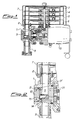
- Figure 1 shows a device according to the invention that comprises a chamber 1 connected upstream with a fitting 2 for the introduction of the sample coming from a delivering unit provided with rotary disks 3, 4, 5, 6 provided inside a cover 7 made of transparent material.
- the chamber 1 of the device is connected downstream with a fitting 6 to feed the sample to the reactor of the analytical apparatus (not shown).
- the moving body 9 has a substantially truncated cone shape, since the latter, together with the conjugated shape and dimensions of the seat, ensures an optimal sealing without however preventing the relative movement of the body 9 with respect to its seat.
- the movement of rotation of the body 9 is preferably obtained by means of a pneumatic actuator 10 through means of motion transmission that also transmit the movement of synchronized rotation to the sample delivering unit placed on top of the device.
- Figure 2 more clearly illustrates the structure of the body 9 in the position, in contact with outside environment, where the sample is received into housing 11.
- the latter is provided in transverse position with respect to the axis of rotation of body 9, and is also aligned upstream with the inlet of the injection duct 2 and downstream with the coaxial opening of duct 8 connected to the combustion reactor of the analytical apparatus (not shown).
- the moving body 9 is provided in a known way with at least one sealing gasket 9' and is urged into the sealing position by Belleville washers 21 or similar elastic means.
- the latter comprises a channel 13 (figures 3, 4), parallel to its axis of rotation, inside which a sloping reflecting surface 14 and a lens 15 make visible to the outside the images coming from inside the combustion reactor.
- Figure 3 is a front view of septum 9 where the presence of the openings of a series of ducts 16, 17, 18 for the circulation of inert gas for sample washing is highlighted.
- Helium is generally used as washing inert gas and preferably the washing gas and the carrier gas are the same.
- an inert gas for washing the sample before the analysis allows to perform combustion in an environment totally deprived of air or of other elements that can affect the analytical result.
- the inert gas is moreover fed at a pressure exceeding the atmospheric pressure or in any case such as to ensure the sealing of the device with respect to the external atmosphere.
- the washing gas is fed through a port 19 of a first duct 20 communicating with the duct 17 inside the body 9.
- the duct 17 allows the washing gas to flow into the front interstice of the seat where the body 9 is positioned.
- the duct 16 allows the washing gas to flow into the housing 11 of the sample while the duct 19 and the O - ring housing are in communication.
- the backside of the body 9 is pneumatically connected to the duct for feeding washing gas, so as to obtain perfect sealing under pressure of the analytical environement with respect to the atmosphere.
Landscapes
- Health & Medical Sciences (AREA)
- Chemical & Material Sciences (AREA)
- Life Sciences & Earth Sciences (AREA)
- Biochemistry (AREA)
- Molecular Biology (AREA)
- Physics & Mathematics (AREA)
- Biomedical Technology (AREA)
- Analytical Chemistry (AREA)
- Engineering & Computer Science (AREA)
- General Health & Medical Sciences (AREA)
- General Physics & Mathematics (AREA)
- Immunology (AREA)
- Pathology (AREA)
- Clinical Laboratory Science (AREA)
- Chemical Kinetics & Catalysis (AREA)
- Investigating Or Analyzing Non-Biological Materials By The Use Of Chemical Means (AREA)
Description
- figure 1 is a cross sectional view of the device according to a preferred embodiment of the invention;
- figure 2 is an enlarged cross sectional view of a detail of figure 1;
- figure 3 is a front view of the rotatable body according to the invention; and
- figure 4 is a sectional view along line A-A of figure 3 of the rotatable body.
Claims (9)
- A device for feeding samples to an apparatus for combustion elemental analysis, of the type comprising supporting means provided with a housing (11) for the sample to be analyzed, said supporting means being movable from an external position where said housing receives the sample, to a position where said housing, isolated from the atmosphere, releases the sample into the analytical apparatus, characterized in that said supporting means is consisting of a sealing moving body (9) rotatable about its axis within a seat (1) having conjugated shape and size.
- A device according to claim 1, wherein said sealing moving body has a substantially truncated cone shape.
- A device according to claim 1, wherein said housing (11) is placed crosswise with respect to the rotation axis of the moving body (9).
- A device according to claim 1 or 3,wherein said housing (11) is alignable upstream with an inlet opening (2) for sample feeding, in contact with the atmosphere, and downstream with an opening (8), insulated from atmosphere, connected to the combustion reactor and coaxial to said inlet opening (2).
- A device according to any of the preceding claims, wherein said moving body (9) comprises one or more ducts (16-20) for circulating a washing gas for insulating said sample and housing (11) from the ambient air.
- A device according to any of the preceding claims, wherein said moving body (9) comprises a channel (13) parallel to the axis of the truncated cone moving body, in which there are provided means (14,15) for visual inspection of the sample introduction into the analytical apparatus.
- A device according to claim 6, wherein said means comprise a sloping reflecting surface (14) placed in correspondence with the intersection between said channel (13) and said housing (11) for the sample, and a lens (15) placed within said channel in correspondence with the surface of the truncated cone body, facing a portion (12) of the external wall of the device made of transparent material.
- A device according to any of the preceding claims, wherein one or more rotatable disc means (3-6), each provided with a plurality of sample housings, are assembled above the housing (11) for the sample and are moved forward step by step thanks to transmission means (10) synchronized with the movement of rotation of the body (9).
- A device according to any of the preceding claims, further comprising a pneumatic actuator (10) for controlling the rotational movement of the moving body and of said rotatable discs.
Applications Claiming Priority (2)
| Application Number | Priority Date | Filing Date | Title |
|---|---|---|---|
| ITMI922035A IT1256356B (en) | 1992-08-31 | 1992-08-31 | DEVICE FOR FEEDING SAMPLES TO ELEMENTARY ANALYSIS EQUIPMENT |
| ITMI922035 | 1992-08-31 |
Publications (3)
| Publication Number | Publication Date |
|---|---|
| EP0585802A2 EP0585802A2 (en) | 1994-03-09 |
| EP0585802A3 EP0585802A3 (en) | 1994-08-17 |
| EP0585802B1 true EP0585802B1 (en) | 1998-04-01 |
Family
ID=11363895
Family Applications (1)
| Application Number | Title | Priority Date | Filing Date |
|---|---|---|---|
| EP93113606A Expired - Lifetime EP0585802B1 (en) | 1992-08-31 | 1993-08-25 | Device for feeding samples to elemental analysis apparatuses |
Country Status (4)
| Country | Link |
|---|---|
| US (1) | US5571480A (en) |
| EP (1) | EP0585802B1 (en) |
| DE (1) | DE69317718T2 (en) |
| IT (1) | IT1256356B (en) |
Families Citing this family (9)
| Publication number | Priority date | Publication date | Assignee | Title |
|---|---|---|---|---|
| IT1256356B (en) * | 1992-08-31 | 1995-12-01 | DEVICE FOR FEEDING SAMPLES TO ELEMENTARY ANALYSIS EQUIPMENT | |
| EP1300195B1 (en) * | 2000-05-22 | 2007-10-31 | Nara Machinery Co., Ltd. | Powder processing unit |
| ITTO20010895A1 (en) * | 2001-09-19 | 2003-03-19 | Eurovector S P A | SAMPLING DEVICE, PARTICULARLY FOR AUTOMATIC ELEMENTARY ANALYZERS. |
| ITTO20010175U1 (en) * | 2001-09-19 | 2003-03-19 | Eurovector S P A | SAMPLER, PARTICULARLY FOR AUTOMATIC ELEMENTARY ANALYZERS. |
| EP1485694A2 (en) * | 2002-03-15 | 2004-12-15 | Carnegie Institution Of Washington | Autosampler loading apparatus |
| US7396512B2 (en) | 2003-11-04 | 2008-07-08 | Drummond Scientific Company | Automatic precision non-contact open-loop fluid dispensing |
| ITMI20041062A1 (en) | 2004-05-26 | 2004-08-26 | Thermo Electron Spa | DEVICE AND WASHING METHOD OF SAMPLES FOR ANALYSIS EQUIPMENT |
| DE202015004524U1 (en) * | 2015-06-24 | 2016-09-29 | C. Gerhardt GmbH & Co. KG | Analysis device for elemental analysis |
| CN109212248B (en) * | 2018-07-20 | 2024-02-13 | 北京诺德泰科仪器仪表有限公司 | Ball valve purging device and method for solid sample injector of elemental analyzer |
Family Cites Families (12)
| Publication number | Priority date | Publication date | Assignee | Title |
|---|---|---|---|---|
| FR1221800A (en) * | 1959-01-13 | 1960-06-03 | Commissariat Energie Atomique | Device for receiving, storing and distributing samples |
| DE1802261A1 (en) * | 1968-10-10 | 1970-11-26 | Bodenseewerk Perkin Elmer Co | Liquid or solid for analysers sample |
| US4055259A (en) * | 1976-03-03 | 1977-10-25 | The Perkin-Elmer Corporation | Sample transport with rotary air interlock charging and discharging means |
| US4244919A (en) * | 1979-03-19 | 1981-01-13 | Hyperion Incorporated | Sample diluting apparatus |
| DE3116049A1 (en) * | 1981-04-22 | 1982-11-11 | Antek Instruments GmbH, 4000 Düsseldorf | COMBUSTION APPARATUS FOR ELEMENTAL ANALYSIS |
| US4462963A (en) * | 1982-03-05 | 1984-07-31 | Leco Corporation | Analytical furnace |
| SE451164B (en) * | 1982-03-22 | 1987-09-07 | Erik Ohlin | DEVICE AND SET FOR SERIAL DILUTION OF A SAMPLE LIQUID |
| US4795614A (en) * | 1987-02-27 | 1989-01-03 | The Perkin-Elmer Corporation | Apparatus for analysis of organic material |
| US4920056A (en) * | 1988-02-19 | 1990-04-24 | The Dow Chemical Company | Apparatus and method for automated microbatch reaction |
| FR2652897B1 (en) * | 1989-10-10 | 1994-01-07 | Institut Francais Petrole | DEVICE AND METHOD FOR TRANSFERRING A SAMPLE OF FLUID BETWEEN TWO CHAMBERS AND APPLICATION IN PARTICULAR TO GAS CHROMATOGRAPHY. |
| DE9209327U1 (en) * | 1992-07-11 | 1992-09-24 | IDC Geräteentwicklungsgesellschaft mbH, 6503 Mainz-Kastel | Device for introducing discrete samples into an analysis room |
| IT1256356B (en) * | 1992-08-31 | 1995-12-01 | DEVICE FOR FEEDING SAMPLES TO ELEMENTARY ANALYSIS EQUIPMENT |
-
1992
- 1992-08-31 IT ITMI922035A patent/IT1256356B/en active IP Right Grant
-
1993
- 1993-08-25 DE DE69317718T patent/DE69317718T2/en not_active Expired - Fee Related
- 1993-08-25 EP EP93113606A patent/EP0585802B1/en not_active Expired - Lifetime
- 1993-08-27 US US08/113,431 patent/US5571480A/en not_active Expired - Lifetime
Also Published As
| Publication number | Publication date |
|---|---|
| DE69317718T2 (en) | 1998-11-19 |
| DE69317718D1 (en) | 1998-05-07 |
| EP0585802A2 (en) | 1994-03-09 |
| US5571480A (en) | 1996-11-05 |
| ITMI922035A1 (en) | 1994-03-03 |
| IT1256356B (en) | 1995-12-01 |
| EP0585802A3 (en) | 1994-08-17 |
| ITMI922035A0 (en) | 1992-08-31 |
Similar Documents
| Publication | Publication Date | Title |
|---|---|---|
| EP0585802A2 (en) | Device for feeding samples to elemental analysis apparatuses | |
| US3690244A (en) | Air valve with fan actuator | |
| US4048498A (en) | Scanning auger microprobe with variable axial aperture | |
| JP2561699B2 (en) | Electron microscope sample device | |
| EP0408804A3 (en) | Analyser for heterogeneous immuno assays | |
| KR890002669A (en) | Liquid handling system | |
| EP0660369A1 (en) | Scan and tilt apparatus for an ion implanter | |
| GB2366376A (en) | Apparatus typically for treating cyto- or histological specimens | |
| EP0280335B1 (en) | Analysis of organic material | |
| EP0285408A2 (en) | Multi-stream fluid sampling valve | |
| US5032361A (en) | Feeding device for introducing liquid or gaseous samples | |
| CA2535155A1 (en) | Sealer for test sample devices | |
| US4817449A (en) | Device for moving samples in a controlled atmosphere enclosure | |
| EP0699282B1 (en) | Selector valve | |
| US4347215A (en) | Device for the automation of at least one operation in an injector for gas chromatographic columns | |
| CN219416920U (en) | Ion thinning device applied to transmission sample preparation | |
| JPH08226876A (en) | Cryostat with cover device-microtome | |
| US4603835A (en) | Shutter mechanism | |
| US5645144A (en) | Control mechanism for sliding panel | |
| US3476936A (en) | Apparatus for positioning specimens in electron microscopes or electron diffraction cameras | |
| US3457789A (en) | Arcuate path diverter with dust closure thereon | |
| EP0794699A3 (en) | Electronic component transferring apparatus | |
| US20080250880A1 (en) | Device and Method for Washing Samples in an Analysis Apparatus | |
| JP3168814B2 (en) | TOF spectrum measuring device | |
| JPS63281341A (en) | X-ray analyzing device provided with energy dispersion type x-ray spectroscope |
Legal Events
| Date | Code | Title | Description |
|---|---|---|---|
| PUAI | Public reference made under article 153(3) epc to a published international application that has entered the european phase |
Free format text: ORIGINAL CODE: 0009012 |
|
| AK | Designated contracting states |
Kind code of ref document: A2 Designated state(s): DE FR GB SE |
|
| PUAL | Search report despatched |
Free format text: ORIGINAL CODE: 0009013 |
|
| AK | Designated contracting states |
Kind code of ref document: A3 Designated state(s): DE FR GB SE |
|
| 17P | Request for examination filed |
Effective date: 19950209 |
|
| RAP1 | Party data changed (applicant data changed or rights of an application transferred) |
Owner name: THERMOQUEST ITALIA S.P.A. |
|
| GRAG | Despatch of communication of intention to grant |
Free format text: ORIGINAL CODE: EPIDOS AGRA |
|
| GRAG | Despatch of communication of intention to grant |
Free format text: ORIGINAL CODE: EPIDOS AGRA |
|
| GRAH | Despatch of communication of intention to grant a patent |
Free format text: ORIGINAL CODE: EPIDOS IGRA |
|
| 17Q | First examination report despatched |
Effective date: 19970825 |
|
| GRAH | Despatch of communication of intention to grant a patent |
Free format text: ORIGINAL CODE: EPIDOS IGRA |
|
| GRAA | (expected) grant |
Free format text: ORIGINAL CODE: 0009210 |
|
| AK | Designated contracting states |
Kind code of ref document: B1 Designated state(s): DE FR GB SE |
|
| PG25 | Lapsed in a contracting state [announced via postgrant information from national office to epo] |
Ref country code: FR Free format text: LAPSE BECAUSE OF FAILURE TO SUBMIT A TRANSLATION OF THE DESCRIPTION OR TO PAY THE FEE WITHIN THE PRESCRIBED TIME-LIMIT Effective date: 19980401 |
|
| REF | Corresponds to: |
Ref document number: 69317718 Country of ref document: DE Date of ref document: 19980507 |
|
| PG25 | Lapsed in a contracting state [announced via postgrant information from national office to epo] |
Ref country code: SE Free format text: LAPSE BECAUSE OF FAILURE TO SUBMIT A TRANSLATION OF THE DESCRIPTION OR TO PAY THE FEE WITHIN THE PRESCRIBED TIME-LIMIT Effective date: 19980701 |
|
| PGFP | Annual fee paid to national office [announced via postgrant information from national office to epo] |
Ref country code: GB Payment date: 19980824 Year of fee payment: 6 |
|
| EN | Fr: translation not filed | ||
| PLBE | No opposition filed within time limit |
Free format text: ORIGINAL CODE: 0009261 |
|
| 26N | No opposition filed | ||
| PG25 | Lapsed in a contracting state [announced via postgrant information from national office to epo] |
Ref country code: GB Free format text: LAPSE BECAUSE OF NON-PAYMENT OF DUE FEES Effective date: 19990825 |
|
| GBPC | Gb: european patent ceased through non-payment of renewal fee |
Effective date: 19990825 |
|
| PGFP | Annual fee paid to national office [announced via postgrant information from national office to epo] |
Ref country code: DE Payment date: 20070830 Year of fee payment: 15 |
|
| PG25 | Lapsed in a contracting state [announced via postgrant information from national office to epo] |
Ref country code: DE Free format text: LAPSE BECAUSE OF NON-PAYMENT OF DUE FEES Effective date: 20090303 |