EP0583123B1 - Apparatus and method for linking an elongated extruded meat product - Google Patents
Apparatus and method for linking an elongated extruded meat product Download PDFInfo
- Publication number
- EP0583123B1 EP0583123B1 EP93306086A EP93306086A EP0583123B1 EP 0583123 B1 EP0583123 B1 EP 0583123B1 EP 93306086 A EP93306086 A EP 93306086A EP 93306086 A EP93306086 A EP 93306086A EP 0583123 B1 EP0583123 B1 EP 0583123B1
- Authority
- EP
- European Patent Office
- Prior art keywords
- linking
- strand
- auger
- auger means
- linking apparatus
- Prior art date
- Legal status (The legal status is an assumption and is not a legal conclusion. Google has not performed a legal analysis and makes no representation as to the accuracy of the status listed.)
- Expired - Lifetime
Links
Images



Classifications
-
- A—HUMAN NECESSITIES
- A22—BUTCHERING; MEAT TREATMENT; PROCESSING POULTRY OR FISH
- A22C—PROCESSING MEAT, POULTRY, OR FISH
- A22C7/00—Apparatus for pounding, forming, or pressing meat, sausage-meat, or meat products
- A22C7/0092—Apparatus for pounding, forming, or pressing meat, sausage-meat, or meat products with worms or other rotary mounted members
-
- A—HUMAN NECESSITIES
- A22—BUTCHERING; MEAT TREATMENT; PROCESSING POULTRY OR FISH
- A22C—PROCESSING MEAT, POULTRY, OR FISH
- A22C11/00—Sausage making ; Apparatus for handling or conveying sausage products during manufacture
- A22C11/10—Apparatus for twisting or linking sausages
Definitions
- Encased meat products have long been linked by means of a pair of linking chains as typically shown in United States Patent No. 3,115,668. These linking chains are expensive to fabricate, and are somewhat difficult to clean. Further, they are an aggressive mechanism and are not suitable for linking a strand of extruded meat product that is fragile and which cannot be rotated prior to being moved through the linking chains.
- a further object of this invention is to provide an apparatus and method for linking a fragile extruded meat product utilizing three elongated identical augers with the meat strand being moved through a central axis among the augers wherein the flighting on the augers intermittently compress the strand to create a link portion.
- the preferred embodiment of this invention provides three parallel auger shafts having identical flighting thereon disposed on axes equally spaced from each other to provide a central axis equidistant from the axes of the augers.
- An elongated strand of extruded meat product is moved through the central axis thereof so that when the flighting on the augers meet at a common point, the diameter of the strand is compressed to create a link in the strand.
- a second embodiment of the invention places the three augers in a rotatable assembly with the augers rotating about their own axes as well as the central axis.
- This embodiment is useful particularly with strands which are particularly fragile and which do not have a separate casing material on the outside thereof.
- a third embodiment of the invention utilizes a casing control element on the inlet end of each auger to cooperate with the nozzle or horn through which the extruded material is being delivered whereupon the control elements rotate the casing material and control the expansion of the casing material to its full diameter as the meat emulsion flows into the casing.
- the sausage encasing machine 10 of Fig. 1 has a frame 12, meat emulsion pump 14, horn 16; chuck 17; and a typical shirred casing 18.
- a looper horn 20 is adapted to convey the linked product to a conventional conveyor 22.
- the foregoing structure is conventional in the art and does not of itself comprise the essence of this invention.
- an auger frame 24 has a gear casing 26 to which is attached a motor 28 which can be either electrically operated or hydraulically operated.
- a drive gear 29 (Fig. 13) is operatively connected to motor 28.
- Three sprocket gears 30 are disposed within gear casing 26 and are interconnected with drive gear 29 by belt 32.
- Three augers 34 are connected to gears 30 by means of stub shaft 36 (Fig. 12).
- a subshaft 38 fits over stubshaft 36 in rigid contact therewith, and a sleeve 40 extends over subshaft 38.
- a threaded rod 42 is secured to sleeve 40 and extends outwardly therefrom.
- Auger shaft 44 slides over sleeve 40 and is rigidly secured thereto by nut 45 on the outer end of rod 42.
- Identical flighting 46 involving substantially one convolution around auger shaft 44 appears on each of the augers 34.
- the flighting has a peripheral edge 49. It is important that each of the auger shafts be synchronized and that the flighting be uniformly positioned on the supporting structure.
- the adjustment means shown in Fig. 11 permits the positions of the three augers 34 to be synchronized insofar as the relative position of the flighting 46 thereon is concerned.
- the three augers are capable of linking an elongated strand of meat product passing therebetween by reason of the flighting 46 on each auger closing in close proximity at a pinch point or linking point 50 as shown typically in Fig. 8.
- the numeral 52 designates the central axis extending through the auger assembly in a direction parallel to and equidistant from the respective longitudinal axes of the three augers 34.
- a gear housing 57 (Fig. 15) includes a drive gear 60 and a planetary gear 62 which has a hollow sleeve which is in rigid contact with drive gear 60.
- Auger gears 30 which have been previously described are rotatably mounted on planetary gear plate 62 and are in rotatable operative contact with gear ring 66.
- a hollow sun gear 67 with outer bore 67A is meshed with each of the auger gears 30.
- the gear 67 of Fig. 15 causes the augers 34 to rotate individually and collectively in the same direction.
- gears 30 when rotational motion is imparted to drive gear 60 from a power source (not shown), planetary gear member 62 is rotated which causes gears 30 to rotate about the central axis 52.
- gears 30 By reason of the engagement of gears 30 with sun gear 67, the gears 30 also rotate about their own respective axes, thus causing the augers to individually rotate about their own axes, and which causes all three augers to rotate about central axis 52.
- a plate 68 journals the opposite ends of the augers 34.
- a string reel 70 is secured to a reel housing 71 which is secured to frame 12.
- String 72 is wound on reel 70 and extends through eyelets 74 and 76 to be wound around the pinch points in strand 54 (Fig. 15) and to extend along the length of each link 56 between the pinch points 50 at opposite ends of each link.
- the string be comprised of a cellulose material which is edible.
- a second embodiment of the invention is shown in Figs. 17-20.
- a casing control element 78 is attached to each of the augers and has a first control surface 80 and a second drive surface 82.
- the control surface 80 is placed close to the horn or nozzle through which the meat emulsion is being extruded, but a small space 84 is left therebetween to permit the casing material to move between the outlet end of the horn or nozzle and the control element.
- the drive surface 82 on control element 78 is the surface that imparts rotational motion to the casing on the outside surface of the strand 54. Beyond the drive surface 82, the casing is permitted to expand to the full diameter thereof whereupon it becomes linked by the augers as previously described.
- control element 78 An alternate form of the control element 78 is shown in Figs. 19 and 20 by the control element 86 which has a first control surface 88 and a drive control surface 90 which perform essentially the same functions as the previously described surfaces 80 and 82, respectively. It is preferred that the diameter of the control elements as measured at the drive surfaces thereof be approximately one and one-half times greater than the diameter of the meat emulsion strand 54 passing between the drive surfaces. This ratio allows the strand to be twisted approximately one and one-half times as the strand encounters the pinch points 50 described heretofore.
- Fig. 21 shows a modified form of the structure of Fig. 2.
- Fig. 21 shows a device capable of linking conventional encased meat emulsion having a shirred casing 18.
- the horn 16 and casing 18 terminate within sun gear and chuck 92 which meshes with the gears 30 and augers 34.
- "Gear-chuck" 92 has a center bore 94 into which chuck insert 96 is slidably inserted.
- Gear-chuck 92 is detachably held within bore 94 by means of resilient O-ring 98 which dwells in arcuate annular grooves in the insert and bore 94 (Fig. 23).
- Insert 96 has a center bore 100 which has a cylindrical aperature 102 inbetween tapered walls 104 and 106. As shown in Fig. 21, the diameter of horn 16 is slightly less than that of aperature 102 to permit casing 18 to be drawn therethrough.
- the chuck insert 96 imparts rotational motion to the casing 18.
- the rotatably filled casing 108 engages augers 34 as described above in regard to the device of Fig. 2, casing 108 will be linked.
- alternate chuck insert 96A can be used (Fig. 22).
- the auger assembly is a vast improvement over the linking chains of the prior art since they are economical of manufacture, more durable and trouble free, and are adapted to effect linking on strands of extruded meat products whether the strands are rotating or not, and whether or not they are encased in a separate casing material.
- the auger assembly is particularly adaptable to linking fragile strands of extruded meat product.
Landscapes
- Engineering & Computer Science (AREA)
- Life Sciences & Earth Sciences (AREA)
- Wood Science & Technology (AREA)
- Zoology (AREA)
- Food Science & Technology (AREA)
- Processing Of Meat And Fish (AREA)
- Formation And Processing Of Food Products (AREA)
- Meat, Egg Or Seafood Products (AREA)
- Extrusion Moulding Of Plastics Or The Like (AREA)
- Containers And Plastic Fillers For Packaging (AREA)
- Beans For Foods Or Fodder (AREA)
- Organic Low-Molecular-Weight Compounds And Preparation Thereof (AREA)
- Supplying Of Containers To The Packaging Station (AREA)
- Auxiliary Devices For And Details Of Packaging Control (AREA)
Abstract
Description
- Encased meat products have long been linked by means of a pair of linking chains as typically shown in United States Patent No. 3,115,668. These linking chains are expensive to fabricate, and are somewhat difficult to clean. Further, they are an aggressive mechanism and are not suitable for linking a strand of extruded meat product that is fragile and which cannot be rotated prior to being moved through the linking chains.
- It is therefore a principal object of this invention to provide an apparatus and method for linking a fragile extruded meat strand which is effective to create the linking function regardless of whether or the meat strand is encased, and regardless of whether or not the meat strand is rotating.
- A further object of this invention is to provide an apparatus and method for linking a fragile extruded meat product utilizing three elongated identical augers with the meat strand being moved through a central axis among the augers wherein the flighting on the augers intermittently compress the strand to create a link portion.
- These and other objects will be apparent to those skilled in the art.
- The preferred embodiment of this invention provides three parallel auger shafts having identical flighting thereon disposed on axes equally spaced from each other to provide a central axis equidistant from the axes of the augers. An elongated strand of extruded meat product is moved through the central axis thereof so that when the flighting on the augers meet at a common point, the diameter of the strand is compressed to create a link in the strand.
- A second embodiment of the invention places the three augers in a rotatable assembly with the augers rotating about their own axes as well as the central axis. This embodiment is useful particularly with strands which are particularly fragile and which do not have a separate casing material on the outside thereof.
- A third embodiment of the invention utilizes a casing control element on the inlet end of each auger to cooperate with the nozzle or horn through which the extruded material is being delivered whereupon the control elements rotate the casing material and control the expansion of the casing material to its full diameter as the meat emulsion flows into the casing.
-
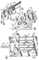
- Fig. 1 is a perspective view of a sausage encasing machine utilizing this invention;
- Fig. 2 is a plan view of the auger assembly of this invention taken on line 2-2 of Fig. 1;
- Fig. 3 is a front elevational view of the auger assembly of this invention taken on line 3-3 of Fig. 2;
- Fig. 4 is a side elevational view of the auger assembly taken on line 4-4 of Fig. 3;
- Fig. 5 is a sectional view of the auger assembly taken on line 5-5 of Fig. 4;
- Fig. 6 is an end elevational view of the auger assembly taken on line 6-6 of Fig. 4;
- Figs. 7, 8 and 9 are elevational views similar to that of Fig. 4 but showing the augers in various positions of rotation;
- Fig. 10 is an exploded view of the auger structure;
- Fig. 11 is a large scale sectional view taken on line 11-11 of Fig. 10;
- Fig. 12 is a sectional view taken on line 12-12 of Fig. 10;
- Fig. 13 is a sectional view through the gear casing of the auger assembly taken on line 13-13 of Fig. 2:
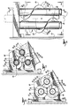
- Fig. 14 is a perspective view of an alternate form of the invention;
- Fig. 15 is a large scale sectional view taken on line 15-15 of Fig. 14;
- Fig. 16 is a small scale sectional view taken on line 16-16 of Fig. 15;
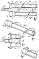
- Fig. 17 is a plan view of a further alternate form of the invention;
- Fig. 18 is a perspective view of the auger structure of Fig. 17;
- Fig. 19 is a partial plan view similar to that of Fig. 17 but shows an alternate casing control element;
- Fig. 20 is a partial perspective view of the control element shown in Fig. 19:
- Fig. 21 is a further alternate form of the invention:
- Fig. 22 is an elongated scale sectional view of the sun gear and chuck of Fig. 21: and
- Fig. 23 is a sectional view of an alternate chuck insert.
- The
sausage encasing machine 10 of Fig. 1 has aframe 12,meat emulsion pump 14,horn 16;chuck 17; and atypical shirred casing 18. A looper horn 20 is adapted to convey the linked product to a conventional conveyor 22. The foregoing structure is conventional in the art and does not of itself comprise the essence of this invention. - With reference to Figs. 2 and 3, an
auger frame 24 has agear casing 26 to which is attached amotor 28 which can be either electrically operated or hydraulically operated. A drive gear 29 (Fig. 13) is operatively connected tomotor 28. Threesprocket gears 30 are disposed withingear casing 26 and are interconnected withdrive gear 29 bybelt 32. - Three
augers 34 are connected togears 30 by means of stub shaft 36 (Fig. 12). Asubshaft 38 fits overstubshaft 36 in rigid contact therewith, and asleeve 40 extends oversubshaft 38. A threadedrod 42 is secured to sleeve 40 and extends outwardly therefrom. Augershaft 44 slides oversleeve 40 and is rigidly secured thereto bynut 45 on the outer end ofrod 42.Identical flighting 46 involving substantially one convolution aroundauger shaft 44 appears on each of theaugers 34. The flighting has aperipheral edge 49. It is important that each of the auger shafts be synchronized and that the flighting be uniformly positioned on the supporting structure. The adjustment means shown in Fig. 11 permits the positions of the threeaugers 34 to be synchronized insofar as the relative position of theflighting 46 thereon is concerned. - The three augers are capable of linking an elongated strand of meat product passing therebetween by reason of the
flighting 46 on each auger closing in close proximity at a pinch point or linkingpoint 50 as shown typically in Fig. 8. Thenumeral 52 designates the central axis extending through the auger assembly in a direction parallel to and equidistant from the respective longitudinal axes of the threeaugers 34. When a strand ofmeat product 54 is moved alongcentral axis 52, theflighting 46 closes on the strand at linkingpoints 50 to compress the body of the strand and create a compressed decreased diameter in the strand at the linking point. As a result,individual links 56 are formed instrand 54. - An alternate form of the invention is shown in Figs. 14-16, and this embodiment is particularly adaptable to very fragile strands of meat product which may not have an artificial casing on the outer surface thereof. A gear housing 57 (Fig. 15) includes a
drive gear 60 and aplanetary gear 62 which has a hollow sleeve which is in rigid contact withdrive gear 60.Auger gears 30 which have been previously described are rotatably mounted onplanetary gear plate 62 and are in rotatable operative contact withgear ring 66. Ahollow sun gear 67 withouter bore 67A is meshed with each of theauger gears 30. Thegear 67 of Fig. 15 causes theaugers 34 to rotate individually and collectively in the same direction. Thus, when rotational motion is imparted to drivegear 60 from a power source (not shown),planetary gear member 62 is rotated which causesgears 30 to rotate about thecentral axis 52. By reason of the engagement ofgears 30 withsun gear 67, thegears 30 also rotate about their own respective axes, thus causing the augers to individually rotate about their own axes, and which causes all three augers to rotate aboutcentral axis 52. - At the other end of the assembly shown in Fig. 15, a
plate 68 journals the opposite ends of theaugers 34. Astring reel 70 is secured to areel housing 71 which is secured toframe 12.String 72 is wound onreel 70 and extends througheyelets link 56 between thepinch points 50 at opposite ends of each link. It is preferred that the string be comprised of a cellulose material which is edible. - A second embodiment of the invention is shown in Figs. 17-20. A
casing control element 78 is attached to each of the augers and has afirst control surface 80 and asecond drive surface 82. Thecontrol surface 80 is placed close to the horn or nozzle through which the meat emulsion is being extruded, but asmall space 84 is left therebetween to permit the casing material to move between the outlet end of the horn or nozzle and the control element. Thedrive surface 82 oncontrol element 78 is the surface that imparts rotational motion to the casing on the outside surface of thestrand 54. Beyond thedrive surface 82, the casing is permitted to expand to the full diameter thereof whereupon it becomes linked by the augers as previously described. - An alternate form of the
control element 78 is shown in Figs. 19 and 20 by thecontrol element 86 which has afirst control surface 88 and adrive control surface 90 which perform essentially the same functions as the previously describedsurfaces meat emulsion strand 54 passing between the drive surfaces. This ratio allows the strand to be twisted approximately one and one-half times as the strand encounters the pinch points 50 described heretofore. - Fig. 21 shows a modified form of the structure of Fig. 2. Fig. 21 shows a device capable of linking conventional encased meat emulsion having a
shirred casing 18. In Fig. 21, thehorn 16 andcasing 18 terminate within sun gear and chuck 92 which meshes with thegears 30 and augers 34. "Gear-chuck" 92 has a center bore 94 into which chuck insert 96 is slidably inserted. Gear-chuck 92 is detachably held withinbore 94 by means of resilient O-ring 98 which dwells in arcuate annular grooves in the insert and bore 94 (Fig. 23). Insert 96 has a center bore 100 which has acylindrical aperature 102 inbetween taperedwalls horn 16 is slightly less than that ofaperature 102 to permit casing 18 to be drawn therethrough. The chuck insert 96 imparts rotational motion to thecasing 18. When the rotatably filledcasing 108 engagesaugers 34 as described above in regard to the device of Fig. 2, casing 108 will be linked. For different diameter casings, or horns,alternate chuck insert 96A can be used (Fig. 22). - It is therefore seen that the auger assembly is a vast improvement over the linking chains of the prior art since they are economical of manufacture, more durable and trouble free, and are adapted to effect linking on strands of extruded meat products whether the strands are rotating or not, and whether or not they are encased in a separate casing material. The auger assembly is particularly adaptable to linking fragile strands of extruded meat product.
- It is therefore seen that the apparatus and method of this invention achieve at least their stated objectives.
Claims (23)
- A linking apparatus for a sausage encasing machine (10) having a meat emulsion extruding element (14-18) including a horn (16), comprising,
a plurality of parallel auger means (34) rotatably mounted on said machine downstream from said meat emulsion extruding element (14-18),
said auger means (34) each including helical elongated flighting elements (46),
said flighting elements having a peripheral edge (49) having a sufficient radius with respect to each of their longitudinal axes so that said peripheral edges of said flighting elements of each auger means will progressively come into close proximity with respect to each other at a linking point (50) on an extended axis of said meat emulsion extruding element (14-18), whereby said linking point (50) will progressively move longitudinally along a central axis parallel to the axes of said auger means (34) when said auger means are all rotated in unison the same direction,
and means (26,28,29,32;57,60,62,66,67) on said machine for rotating said auger means in unison in one direction. - The linking apparatus of claim 1 wherein each of said auger means (34) has a longitudinal axis which is equally spaced with respect to each other.
- The linking apparatus of claim 1 wherein the flighting elements (46) on each auger means (34) are identical.
- The linking apparatus of claim 1 wherein each of said auger means (34) includes an elongated center shaft (36,38) on the longitudinal axis thereof, a casing control element (78;86) on each of said shafts adjacent said outlet end of said extruding element (14-18) and being positioned upstream of said flighting elements (46), each of said control elements having a first control surface (80) which is closely spaced with respect to the outside surface of said extruding element (17) so as to permit a tubular casing (18) to move longitudinally between said outside surface of said extruding element (17) and said first control surface (80).
- The linking apparatus of claim 4 wherein said control elements (78;86) are rotatably mounted on said center shafts.
- The linking apparatus of claim 4 wherein said control elements (78,86) have a second control surface (82) downstream from said first control surface (80), said control elements having an effective diameter at said first control surface that is greater than at said second control surface to permit the effective diameter of a casing (18) moving from said horn to increase in diameter as it moves from said first control surface to said second control surface.
- The linking apparatus of claim 1 wherein three auger means (34) are rotatably mounted on said machine downstream from said meat emulsion extruding element (14-18).
- The linking apparatus of claim 7 wherein said auger means (34) are mounted on a rotatable frame means (62,68) to permit said three auger means (34) to rotate as a unit around an axis (52) equidistant from the axes of said three auger means while each of said auger means rotates about its own longitudinal axis, and means (57,60,62,66,67,68) on said machine for rotating said frame means.
- The linking apparatus of claim 8 wherein a reel (70) of string (72) is positioned on said frame means (68), and a length of string (72) extends therefrom, said length of string extending from said reel into the path of an elongated strand of meat emulsion (54) extruded from said extruding element (17) and moving along the axis (52) of said frame means, to encircle said strand where said strand has encountered said linking point, and to extend along the length of said strand inbetween the positions that said string has encountered said linking point.
- The linking apparatus of claim 9 wherein said string (72) is comprised of an edible substance.
- The linking apparatus of claim 1 wherein said linking point of said flighting elements (46) is adapted to create links in an elongated strand of meat emulsion passing along said central axis.
- The linking apparatus of claim 1 wherein a sun gear (67) with a center bore therein is in mesh with gears (30) on each of said auger means (34).
- The linking apparatus of claim 8 wherein a sun gear (67) with a center bore therein is in mesh with gears (30) on each of said auger means (34).
- The linking apparatus of claim 12 wherein a chuck insert (96) is in the center bore (94) of said sun gear (92) to impart rotational motion to an elongated casing (18) passing through said center bore (94), and said meat emulsion extruding element (16) having an outlet end in close proximity with said chuck insert (96).
- The linking apparatus of claim 14 wherein said chuck insert (96) is detachably mounted in said center bore of said sun gear.
- The linking apparatus of claim 15 wherein said chuck insert (96) has a cylindrical aperture (102) between opposite walls (104,106) tapered outwardly therefrom.
- The linking apparatus of claim 8 wherein a reel (70) of string (72) is positioned on said frame means (68), and a length of string (72) extends therefrom, said length of string extending from said reel (70) into the path of an elongated strand of meat emulsion (54) extruded from said extruding element (17) and moving along the axis (52) of said frame means, to encircle said strand where said strand has encountered said linking point, and to extend along the length of said strand inbetween the positions that said string has encountered said linking point.
- The linking apparatus of claim 12 wherein a chuck insert (67,96) is operationally connected to said sun gear (67,92) to impart rotational motion to an elongated casing (18) passing through said center bore, and said meat emulsion extruding element (16) having an outlet end in close proximity with said chuck insert (96).
- The method of use of the apparatus of claim 1, comprising, passing an elongated strand of meat product (54) along said central axis (52) whereby the link point on said auger flighting will progressively create a plurality of links along the length of said strand.
- The method of claim 19 wherein said elongated strand is not rotating as it moves along said central axis (52).
- The method of claim 19 wherein said auger means are rotated about said central axis (52).
- The method of claim 21 wherein said string (72) is progressively wrapped around said elongated strand at said linking point and extends along the length of each link to the next succeeding linking point.
- The method of claim 19 wherein said auger means (34) are rotated in the same direction about their respective axes and about said central axis (52).
Applications Claiming Priority (2)
| Application Number | Priority Date | Filing Date | Title |
|---|---|---|---|
| US07/928,951 US5279516A (en) | 1992-08-11 | 1992-08-11 | Apparatus and method for linking an elongated extruded meat product |
| US928951 | 1997-09-12 |
Publications (2)
| Publication Number | Publication Date |
|---|---|
| EP0583123A1 EP0583123A1 (en) | 1994-02-16 |
| EP0583123B1 true EP0583123B1 (en) | 1996-11-27 |
Family
ID=25457072
Family Applications (1)
| Application Number | Title | Priority Date | Filing Date |
|---|---|---|---|
| EP93306086A Expired - Lifetime EP0583123B1 (en) | 1992-08-11 | 1993-08-02 | Apparatus and method for linking an elongated extruded meat product |
Country Status (15)
| Country | Link |
|---|---|
| US (1) | US5279516A (en) |
| EP (1) | EP0583123B1 (en) |
| JP (1) | JPH0748974B2 (en) |
| KR (1) | KR970002583B1 (en) |
| AT (1) | ATE145519T1 (en) |
| AU (1) | AU658319B2 (en) |
| BR (1) | BR9303348A (en) |
| CA (1) | CA2101831C (en) |
| DE (2) | DE69306193T2 (en) |
| DK (1) | DK0583123T3 (en) |
| ES (1) | ES2096869T3 (en) |
| FI (1) | FI103942B1 (en) |
| NO (1) | NO301512B1 (en) |
| NZ (1) | NZ248315A (en) |
| ZA (1) | ZA935633B (en) |
Families Citing this family (6)
| Publication number | Priority date | Publication date | Assignee | Title |
|---|---|---|---|---|
| IT1290475B1 (en) * | 1997-03-26 | 1998-12-04 | Righele Giovanni | MACHINE TO PRODUCE SAUSAGES WITH TWISTED PORK |
| WO2000065921A1 (en) * | 1999-05-02 | 2000-11-09 | Hitec Co., Ltd. | Method and device for manufacturing chain food such as sausage |
| DE10115466A1 (en) | 2000-03-31 | 2001-10-31 | Hitec Co Ltd | Method and apparatus for making associated twisted area food products such as sausages |
| DE502004004082D1 (en) * | 2004-04-01 | 2007-07-26 | Handtmann Albert Maschf | Apparatus and method for separating a sausage strand |
| US20080145495A1 (en) | 2006-10-30 | 2008-06-19 | Sara Lee Corporation | System and method for conditioning food product |
| EP3398439B1 (en) * | 2013-02-01 | 2024-08-14 | GEA Food Solutions Bakel B.V. | Food forming drum |
Family Cites Families (14)
| Publication number | Priority date | Publication date | Assignee | Title |
|---|---|---|---|---|
| DE119006C (en) * | ||||
| US1431227A (en) * | 1922-10-10 | Implication | ||
| US661073A (en) * | 1899-04-20 | 1900-11-06 | Wilhelm Paulitschke | Sausage stuffing and linking machine. |
| US870972A (en) * | 1906-10-04 | 1907-11-12 | Allan F Little | Sausage-linking machine. |
| US2133463A (en) * | 1935-08-24 | 1938-10-18 | Visking Corp | Sausage-linking machine |
| US2356099A (en) * | 1942-01-14 | 1944-08-15 | Sr Richard Swoboda | Sausage linking machine |
| US2492222A (en) * | 1946-06-17 | 1949-12-27 | Parker A Jacobson | Sausage machine |
| US2477031A (en) * | 1948-09-14 | 1949-07-26 | Christ W Eckert | Sausage linking machine |
| GB659014A (en) * | 1948-09-21 | 1951-10-17 | American Viscose Corp | Method and apparatus for forming, stuffing, and shaping casings |
| US2834042A (en) * | 1954-04-14 | 1958-05-13 | Lawrence P Cross | Sausage linking machine |
| US3115668A (en) * | 1962-05-14 | 1963-12-31 | Townsend Engineering Co | Machine for encasing sausage and the like |
| FR1557553A (en) * | 1967-03-31 | 1969-02-14 | ||
| DE3206956A1 (en) * | 1981-03-05 | 1982-09-16 | C. Hoegger & Cie. AG, 9202 Gossau | FEEDING MACHINE AND RECEIVER FOR PORTIONED SAUSAGE CHAINS |
| IT210017Z2 (en) * | 1987-03-03 | 1988-11-14 | Righele Giovanni | PERFECTED BINDING MACHINE FOR SAUSAGES. |
-
1992
- 1992-08-11 US US07/928,951 patent/US5279516A/en not_active Expired - Fee Related
-
1993
- 1993-08-02 AT AT93306086T patent/ATE145519T1/en not_active IP Right Cessation
- 1993-08-02 EP EP93306086A patent/EP0583123B1/en not_active Expired - Lifetime
- 1993-08-02 ES ES93306086T patent/ES2096869T3/en not_active Expired - Lifetime
- 1993-08-02 DK DK93306086.5T patent/DK0583123T3/en active
- 1993-08-02 DE DE69306193T patent/DE69306193T2/en not_active Expired - Fee Related
- 1993-08-02 NO NO932757A patent/NO301512B1/en not_active IP Right Cessation
- 1993-08-03 NZ NZ248315A patent/NZ248315A/en unknown
- 1993-08-03 CA CA002101831A patent/CA2101831C/en not_active Expired - Fee Related
- 1993-08-03 FI FI933449A patent/FI103942B1/en active
- 1993-08-04 ZA ZA935633A patent/ZA935633B/en unknown
- 1993-08-04 AU AU44416/93A patent/AU658319B2/en not_active Ceased
- 1993-08-10 DE DE9311939U patent/DE9311939U1/en not_active Expired - Lifetime
- 1993-08-10 JP JP5218110A patent/JPH0748974B2/en not_active Expired - Lifetime
- 1993-08-10 BR BR9303348A patent/BR9303348A/en not_active IP Right Cessation
- 1993-08-11 KR KR1019930015523A patent/KR970002583B1/en not_active Expired - Fee Related
Also Published As
| Publication number | Publication date |
|---|---|
| FI103942B (en) | 1999-10-29 |
| NZ248315A (en) | 1995-04-27 |
| DK0583123T3 (en) | 1997-05-26 |
| CA2101831A1 (en) | 1994-02-12 |
| FI103942B1 (en) | 1999-10-29 |
| AU658319B2 (en) | 1995-04-06 |
| ATE145519T1 (en) | 1996-12-15 |
| CA2101831C (en) | 1996-04-16 |
| DE69306193T2 (en) | 1997-05-22 |
| AU4441693A (en) | 1994-02-17 |
| ES2096869T3 (en) | 1997-03-16 |
| KR970002583B1 (en) | 1997-03-06 |
| JPH06178645A (en) | 1994-06-28 |
| DE9311939U1 (en) | 1993-10-07 |
| BR9303348A (en) | 1994-03-15 |
| FI933449A0 (en) | 1993-08-03 |
| EP0583123A1 (en) | 1994-02-16 |
| FI933449A7 (en) | 1994-02-12 |
| US5279516A (en) | 1994-01-18 |
| NO932757D0 (en) | 1993-08-02 |
| NO932757L (en) | 1994-02-14 |
| NO301512B1 (en) | 1997-11-10 |
| JPH0748974B2 (en) | 1995-05-31 |
| DE69306193D1 (en) | 1997-01-09 |
| ZA935633B (en) | 1994-03-07 |
| KR940003465A (en) | 1994-03-12 |
Similar Documents
| Publication | Publication Date | Title |
|---|---|---|
| CA2101831C (en) | Apparatus and method for linking an elongated extruded meat product | |
| US3964128A (en) | Apparatus for encasing a product | |
| US4802511A (en) | Shirred tubular material | |
| EP0846547B1 (en) | Method and apparatus for continuously curving thermoplastic shrinkable tubular casings | |
| JP3571406B2 (en) | Manufacturing equipment for sausages, etc. | |
| DE2230436C3 (en) | Device for the production of self-supporting sticks from shirred and compressed sausage casing | |
| NZ247761A (en) | Sausage stuffing machine with means for placing liquid film on interior of sausage casing before meat emulsion enters casing; liquid placed on exterior surface of stuffing horn | |
| DE69009021T2 (en) | Filling tube with spring for calibration. | |
| CA2005525C (en) | Encased product and method for encasing the same | |
| DE3615478C2 (en) | ||
| US5993868A (en) | Method for applying a liquid to the surface of an extruded strand of meat emulsion | |
| US4001914A (en) | Process and apparatus for shirring tubular casings | |
| US3869756A (en) | Shirred casing stick with reverse helical fold pattern | |
| US4956893A (en) | Apparatus for encasing a product | |
| DE19710402A1 (en) | Method and device for producing hoses or sleeves in a curved shape | |
| DE1632190A1 (en) | Method and device for the spiral movement of cylindrical objects in a row | |
| US6616521B1 (en) | Method and means for creating a casing on a sausage making machine | |
| DE60033858T2 (en) | Method and device for filling natural sausage casings | |
| SE8901473L (en) | ENCAPPED PRODUCT AND PROCEDURE AND DEVICE FOR ENCAPPING THEM | |
| ES8203292A1 (en) | Apparatus for axially shirring tubular casings, especially for sausage making. | |
| DE9416580U1 (en) | Device for the axial gathering of tubular film |
Legal Events
| Date | Code | Title | Description |
|---|---|---|---|
| PUAI | Public reference made under article 153(3) epc to a published international application that has entered the european phase |
Free format text: ORIGINAL CODE: 0009012 |
|
| AK | Designated contracting states |
Kind code of ref document: A1 Designated state(s): AT BE CH DE DK ES FR GB GR IE IT LI LU NL PT SE |
|
| 17P | Request for examination filed |
Effective date: 19940323 |
|
| 17Q | First examination report despatched |
Effective date: 19950804 |
|
| GRAG | Despatch of communication of intention to grant |
Free format text: ORIGINAL CODE: EPIDOS AGRA |
|
| GRAH | Despatch of communication of intention to grant a patent |
Free format text: ORIGINAL CODE: EPIDOS IGRA |
|
| GRAH | Despatch of communication of intention to grant a patent |
Free format text: ORIGINAL CODE: EPIDOS IGRA |
|
| GRAA | (expected) grant |
Free format text: ORIGINAL CODE: 0009210 |
|
| AK | Designated contracting states |
Kind code of ref document: B1 Designated state(s): AT BE CH DE DK ES FR GB GR IE IT LI LU NL PT SE |
|
| PG25 | Lapsed in a contracting state [announced via postgrant information from national office to epo] |
Ref country code: GR Free format text: LAPSE BECAUSE OF FAILURE TO SUBMIT A TRANSLATION OF THE DESCRIPTION OR TO PAY THE FEE WITHIN THE PRESCRIBED TIME-LIMIT Effective date: 19961127 Ref country code: AT Effective date: 19961127 |
|
| REF | Corresponds to: |
Ref document number: 145519 Country of ref document: AT Date of ref document: 19961215 Kind code of ref document: T |
|
| ITF | It: translation for a ep patent filed | ||
| ET | Fr: translation filed | ||
| REG | Reference to a national code |
Ref country code: IE Ref legal event code: FG4D Free format text: 70775 |
|
| REF | Corresponds to: |
Ref document number: 69306193 Country of ref document: DE Date of ref document: 19970109 |
|
| REG | Reference to a national code |
Ref country code: CH Ref legal event code: NV Representative=s name: AMMANN PATENTANWAELTE AG BERN |
|
| REG | Reference to a national code |
Ref country code: ES Ref legal event code: FG2A Ref document number: 2096869 Country of ref document: ES Kind code of ref document: T3 |
|
| REG | Reference to a national code |
Ref country code: DK Ref legal event code: T3 |
|
| REG | Reference to a national code |
Ref country code: PT Ref legal event code: SC4A Free format text: AVAILABILITY OF NATIONAL TRANSLATION Effective date: 19970226 |
|
| PLBE | No opposition filed within time limit |
Free format text: ORIGINAL CODE: 0009261 |
|
| STAA | Information on the status of an ep patent application or granted ep patent |
Free format text: STATUS: NO OPPOSITION FILED WITHIN TIME LIMIT |
|
| 26N | No opposition filed | ||
| PGFP | Annual fee paid to national office [announced via postgrant information from national office to epo] |
Ref country code: DE Payment date: 20010723 Year of fee payment: 9 |
|
| PGFP | Annual fee paid to national office [announced via postgrant information from national office to epo] |
Ref country code: PT Payment date: 20010727 Year of fee payment: 9 |
|
| PGFP | Annual fee paid to national office [announced via postgrant information from national office to epo] |
Ref country code: CH Payment date: 20010730 Year of fee payment: 9 |
|
| PGFP | Annual fee paid to national office [announced via postgrant information from national office to epo] |
Ref country code: GB Payment date: 20010801 Year of fee payment: 9 |
|
| PGFP | Annual fee paid to national office [announced via postgrant information from national office to epo] |
Ref country code: SE Payment date: 20010807 Year of fee payment: 9 |
|
| PGFP | Annual fee paid to national office [announced via postgrant information from national office to epo] |
Ref country code: LU Payment date: 20010808 Year of fee payment: 9 |
|
| PGFP | Annual fee paid to national office [announced via postgrant information from national office to epo] |
Ref country code: FR Payment date: 20010810 Year of fee payment: 9 Ref country code: DK Payment date: 20010810 Year of fee payment: 9 |
|
| PGFP | Annual fee paid to national office [announced via postgrant information from national office to epo] |
Ref country code: IE Payment date: 20010823 Year of fee payment: 9 |
|
| PGFP | Annual fee paid to national office [announced via postgrant information from national office to epo] |
Ref country code: ES Payment date: 20010824 Year of fee payment: 9 |
|
| PGFP | Annual fee paid to national office [announced via postgrant information from national office to epo] |
Ref country code: NL Payment date: 20010830 Year of fee payment: 9 |
|
| PGFP | Annual fee paid to national office [announced via postgrant information from national office to epo] |
Ref country code: BE Payment date: 20010927 Year of fee payment: 9 |
|
| REG | Reference to a national code |
Ref country code: GB Ref legal event code: IF02 |
|
| PG25 | Lapsed in a contracting state [announced via postgrant information from national office to epo] |
Ref country code: LU Free format text: LAPSE BECAUSE OF NON-PAYMENT OF DUE FEES Effective date: 20020802 Ref country code: IE Free format text: LAPSE BECAUSE OF NON-PAYMENT OF DUE FEES Effective date: 20020802 Ref country code: GB Free format text: LAPSE BECAUSE OF NON-PAYMENT OF DUE FEES Effective date: 20020802 |
|
| PG25 | Lapsed in a contracting state [announced via postgrant information from national office to epo] |
Ref country code: SE Free format text: LAPSE BECAUSE OF NON-PAYMENT OF DUE FEES Effective date: 20020803 Ref country code: ES Free format text: LAPSE BECAUSE OF NON-PAYMENT OF DUE FEES Effective date: 20020803 |
|
| PG25 | Lapsed in a contracting state [announced via postgrant information from national office to epo] |
Ref country code: LI Free format text: LAPSE BECAUSE OF NON-PAYMENT OF DUE FEES Effective date: 20020831 Ref country code: DK Free format text: LAPSE BECAUSE OF NON-PAYMENT OF DUE FEES Effective date: 20020831 Ref country code: CH Free format text: LAPSE BECAUSE OF NON-PAYMENT OF DUE FEES Effective date: 20020831 Ref country code: BE Free format text: LAPSE BECAUSE OF NON-PAYMENT OF DUE FEES Effective date: 20020831 |
|
| BERE | Be: lapsed |
Owner name: *TOWNSEND ENGINEERING CY Effective date: 20020831 |
|
| PG25 | Lapsed in a contracting state [announced via postgrant information from national office to epo] |
Ref country code: PT Free format text: LAPSE BECAUSE OF NON-PAYMENT OF DUE FEES Effective date: 20030228 |
|
| PG25 | Lapsed in a contracting state [announced via postgrant information from national office to epo] |
Ref country code: NL Free format text: LAPSE BECAUSE OF NON-PAYMENT OF DUE FEES Effective date: 20030301 Ref country code: DE Free format text: LAPSE BECAUSE OF NON-PAYMENT OF DUE FEES Effective date: 20030301 |
|
| GBPC | Gb: european patent ceased through non-payment of renewal fee |
Effective date: 20020802 |
|
| EUG | Se: european patent has lapsed | ||
| REG | Reference to a national code |
Ref country code: DK Ref legal event code: EBP |
|
| REG | Reference to a national code |
Ref country code: CH Ref legal event code: PL |
|
| PG25 | Lapsed in a contracting state [announced via postgrant information from national office to epo] |
Ref country code: FR Free format text: LAPSE BECAUSE OF NON-PAYMENT OF DUE FEES Effective date: 20030430 |
|
| NLV4 | Nl: lapsed or anulled due to non-payment of the annual fee |
Effective date: 20030301 |
|
| REG | Reference to a national code |
Ref country code: IE Ref legal event code: MM4A |
|
| REG | Reference to a national code |
Ref country code: FR Ref legal event code: ST |
|
| REG | Reference to a national code |
Ref country code: ES Ref legal event code: FD2A Effective date: 20030912 |
|
| PG25 | Lapsed in a contracting state [announced via postgrant information from national office to epo] |
Ref country code: IT Free format text: LAPSE BECAUSE OF NON-PAYMENT OF DUE FEES;WARNING: LAPSES OF ITALIAN PATENTS WITH EFFECTIVE DATE BEFORE 2007 MAY HAVE OCCURRED AT ANY TIME BEFORE 2007. THE CORRECT EFFECTIVE DATE MAY BE DIFFERENT FROM THE ONE RECORDED. Effective date: 20050802 |