EP0582393B1 - Ceramic membrane removal tool - Google Patents
Ceramic membrane removal tool Download PDFInfo
- Publication number
- EP0582393B1 EP0582393B1 EP93305496A EP93305496A EP0582393B1 EP 0582393 B1 EP0582393 B1 EP 0582393B1 EP 93305496 A EP93305496 A EP 93305496A EP 93305496 A EP93305496 A EP 93305496A EP 0582393 B1 EP0582393 B1 EP 0582393B1
- Authority
- EP
- European Patent Office
- Prior art keywords
- filter housing
- removal tool
- membranes
- tool
- housing
- Prior art date
- Legal status (The legal status is an assumption and is not a legal conclusion. Google has not performed a legal analysis and makes no representation as to the accuracy of the status listed.)
- Expired - Lifetime
Links
Images


Classifications
-
- B—PERFORMING OPERATIONS; TRANSPORTING
- B25—HAND TOOLS; PORTABLE POWER-DRIVEN TOOLS; MANIPULATORS
- B25B—TOOLS OR BENCH DEVICES NOT OTHERWISE PROVIDED FOR, FOR FASTENING, CONNECTING, DISENGAGING, OR HOLDING
- B25B27/00—Hand tools, specially adapted for fitting together or separating parts or objects whether or not involving some deformation, not otherwise provided for
- B25B27/02—Hand tools, specially adapted for fitting together or separating parts or objects whether or not involving some deformation, not otherwise provided for for connecting objects by press fit or detaching same
- B25B27/023—Hand tools, specially adapted for fitting together or separating parts or objects whether or not involving some deformation, not otherwise provided for for connecting objects by press fit or detaching same using screws
-
- B—PERFORMING OPERATIONS; TRANSPORTING
- B01—PHYSICAL OR CHEMICAL PROCESSES OR APPARATUS IN GENERAL
- B01D—SEPARATION
- B01D65/00—Accessories or auxiliary operations, in general, for separation processes or apparatus using semi-permeable membranes
-
- B—PERFORMING OPERATIONS; TRANSPORTING
- B01—PHYSICAL OR CHEMICAL PROCESSES OR APPARATUS IN GENERAL
- B01D—SEPARATION
- B01D2201/00—Details relating to filtering apparatus
- B01D2201/24—Tools used for the removal of filters
-
- Y—GENERAL TAGGING OF NEW TECHNOLOGICAL DEVELOPMENTS; GENERAL TAGGING OF CROSS-SECTIONAL TECHNOLOGIES SPANNING OVER SEVERAL SECTIONS OF THE IPC; TECHNICAL SUBJECTS COVERED BY FORMER USPC CROSS-REFERENCE ART COLLECTIONS [XRACs] AND DIGESTS
- Y10—TECHNICAL SUBJECTS COVERED BY FORMER USPC
- Y10T—TECHNICAL SUBJECTS COVERED BY FORMER US CLASSIFICATION
- Y10T29/00—Metal working
- Y10T29/53—Means to assemble or disassemble
- Y10T29/53796—Puller or pusher means, contained force multiplying operator
- Y10T29/53848—Puller or pusher means, contained force multiplying operator having screw operator
- Y10T29/53857—Central screw, work-engagers around screw
- Y10T29/53861—Work-engager arms along or parallel to screw
Definitions
- This invention relates to removal tools and more particularly tools for removing filter membranes from housings.
- Ceramic membrane ultrafiltration has been used for a number of years in the laboratory to purify materials. Recently ceramic membrane ultrafiltration has been adapted for the purification of large quantities of compounds in chemical processing plants. Because of the large scales involved the ultrafiltration apparatuses are different in configuration from laboratory ultrafiltration systems.
- One type of large-scale ultrafiltration apparatus comprises a canister housing including a plurality of parallel running filter membranes. The membranes pass through holes at the inlet and outlet of the empty canister. Rubber grommets fitted to the membranes at the canister holes provide an extremely secure fit.
- the solution or suspension to be filtered cycles repeatedly through bores in the filter membrane.
- the permeate is filtered through the porous ceramic membrane into the canister housing interior and exits the canister housing interior through additional outlets. Typically provision is made for cleaning the ceramic membranes through these additional outlets by backflushing.
- the membranes tend to become “locked” in place.
- the membranes are typically made of a brittle ceramic, it can be difficult to remove the membranes from the canister without breaking them.
- One removal technique utilizes a hammer and polypropylene pin to drive the membrane through the holes. However, typically this results in a broken membrane.
- This invention is directed to a tool for removing membranes from a filter housing without breaking the membranes during removal.
- the tool comprises a threaded screw means for pressing the membrane through aligned housing holes in opposing sides of the filter housing and a guide means for maintaining the screw means substantially aligned with the filter housing holes.
- the guide means has a threaded hole for receiving the threaded screw means therethrough.
- the tool also comprises a beam and a pair of removable fastening means for clamping the tool to the filter housing.
- the pair of fastening means are slidably retained along the beam.
- the guide means is slidably retained along the beam and disposed between the fastening means.
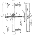
- Figure 1 is a side view of the removal tool partly broken away to illustrate the guide mechanism and ball and socket swivel joint.
- Figure 2 is a sectional view taken along line 2 - 2 of Figure 1 with the fastening means removed for clarity.
- Figure 3 is a perspective view of the attachment of the removal tool to the housing showing alternate attachment configurations in phantom.
- Figure 4 is a perspective view of the filter housing and attached removal tool partly broken away to illustrate the parallel membranes passing through the housing.
- Figure 5 is a side view of the filter housing and attached removal tool partly broken away and partly in phantom to illustrate the removal of a membrane from the housing.
- Figure 5A is an expanded view of the filter housing view in Figure 5 that is broken away.
- a beam 3 has a slot 6 and a pair of fastening means (e.g. bolts 9 and nuts 12) extending through the slot 6.
- the nuts 12 have plates 15 attached thereto and extending radially outward therefrom.
- the plates 15 facilitate attachment to the filter housing.
- the bolts 9 have a head 18 or washer sized so that the bolt 9 cannot pass completely through the beam slot 6 (e.g. the bolt head has a larger diameter than the slot width).
- the bolts 9 and nuts 12 are slidably retained along the beam slot 6.
- a guide means such as a spool 21 extends through the beam slot 6 and is slidably retained along the beam slot by the spool ends 24 which extend radially outward from the spool 21 and have a larger diameter than the beam slot 6.
- the guide means is disposed between the fastening means.
- the length of the spool 21 between the ends 24 is only slightly larger than the thickness of the beam 3 in order to facilitate the spool's 21 guidance function.
- the spool 21 has a threaded hole extending therethrough.
- a screw means such as a threaded shaft 27 having a handle 30 attached thereto is screwed through the threaded spool 21.
- the spool 21 guides the threaded shaft 27 in the desired direction.
- Extending from the threaded shaft 27 on the opposing side of the beam 3 from the handle 30 is a ball 33.
- a socket 36 encloses the ball 33 to form a freely rotatable ball and socket swivel joint.
- Extending from the socket 36 is a cushioned end 39 (e.g. polytetrafluoroethylene end).
- a pin 42 typically a pair of pins).
- the beam 3, bolts 9 and nuts 12, spool 21, threaded shaft 27, and freely rotatable socket 36 - pin 42 structure form an exemplary removal tool 45 of this invention.
- Figure 3 illustrates the attachment of the removal tool 45 to the filter housing 48.
- the cylindrical filter housing 48 has a lip 51 extending therefrom and the removal tool 45 clamps to the lip 51 of filter housing 48.
- the slotted beam 3 lays across the filter housing lip 51.
- the nut plates 15 extend underneath the filter housing lip 51 and on the opposing side of the lip 51 from the slotted beam 3.
- the bolt heads 18 are on the side of the beam 3 opposite to the nut plate 15.
- the bolts extend through the slotted beam 3 and are fastened to the nut plates 15, thus clamping the removal tool to the filter housing lip 51.
- the threaded shaft 27 and spool 21 are free to slide along the beam 3 in order to facilitate positioning of the shaft 27 directly over the desired position.
- Figure 3 illustrates phantom removal tools 54, 57 configured in alternative positions relative to the filter housing lip 51.
- phantom removal tool (57) illustrates an embodiment where the removal tool 57 does not cross the center. The freedom of movement of the fastening means along the beam 3 facilitates the above embodiment.
- the removal tool 45 is clamped to the filter housing 48.
- the filter housing is partly broken away to show a plurality of membranes (i.e. filters) 60 that extend in parallel fashion through the open filter housing 48 from the inlet 66 to the outlet 63 of the housing 48.
- the membranes 60 are typically made of a brittle ceramic material.
- the membranes 60 are held in holes 69 in the housing inlet 66 by flexible grommets (e.g. rubber) to form an interference fit.
- the membranes 60 are secured in corresponding holes in the housing outlet 63 by additional grommets.
- the membranes are also retained from movement in the fluid flow direction (i.e., inlet 66 to outlet 63) by housing retaining rings 80 against which the membranes 60 are seated.
- the membranes 60 have a plurality of bores 72 that run the length of the membranes 60.
- the removal tool 45 is clamped to the outlet 63 side of the filter housing 48.
- the filter housing 48 is partly broken away at the outlet 63 to illustrate the abutting of the cushioned tip 39 of the shaft 27 to the membrane 60 and thus the removal of the membrane 60 from the housing 48.
- the shaft 27 and thus cushioned tip 39 are in alignment with the membrane in need of removal.
- the handle 30 is rotated to thread the shaft 27 through the guide spool 21, rubber grommet 90 and housing retaining ring 80 resulting in the upward movement of the cushioned tip 39.
- the pins 42 are aligned with and extend into the membrane bores 72 to facilitate maintenance of a steady linear pressure in order to avoid the membranes cocking at an angle once the membrane 60 clears the outlet 63 of the filter housing 48.
- the ball and socket swivel joint allows free rotation of the cushioned tip 39 relative to the threaded shaft 27 so that the cushioned tip 39 does not cause the membrane 60 to twist and potentially cause membrane 60 breakage. Once the membrane 60 has been pushed a convenient distance from filter housing top 66 it may be manually removed without breakage.
- the fluid flow direction is from inlet 66 to outlet 63.
- the filter housing may be disposed in-line in conventional chemical processing equipment.
- the fluid to be filtered flows through the membrane bores 72, laterally through ceramic membrane pores 81 into the housing interior 75 and exits through additional housing outlets 78.
- a pair of outlets 78 provides provision for cleaning the ceramic membranes by backflushing.
- the ceramic membranes are selected to provide the desired pore size and thus filtration.
- this invention makes a significant advance in the field of removal tools by providing a removal tool that provides a positive non-twisting aligned pressure to remove membranes without breakage.
- the removal tool accommodates a wide variety of filter housings and membrane positions.
Landscapes
- Engineering & Computer Science (AREA)
- Mechanical Engineering (AREA)
- Chemical & Material Sciences (AREA)
- Chemical Kinetics & Catalysis (AREA)
- Separation Using Semi-Permeable Membranes (AREA)
- Polishing Bodies And Polishing Tools (AREA)
- Thermistors And Varistors (AREA)
Abstract
Description
- This invention relates to removal tools and more particularly tools for removing filter membranes from housings.
- Ceramic membrane ultrafiltration has been used for a number of years in the laboratory to purify materials. Recently ceramic membrane ultrafiltration has been adapted for the purification of large quantities of compounds in chemical processing plants. Because of the large scales involved the ultrafiltration apparatuses are different in configuration from laboratory ultrafiltration systems. One type of large-scale ultrafiltration apparatus comprises a canister housing including a plurality of parallel running filter membranes. The membranes pass through holes at the inlet and outlet of the empty canister. Rubber grommets fitted to the membranes at the canister holes provide an extremely secure fit. The solution or suspension to be filtered cycles repeatedly through bores in the filter membrane. The permeate is filtered through the porous ceramic membrane into the canister housing interior and exits the canister housing interior through additional outlets. Typically provision is made for cleaning the ceramic membranes through these additional outlets by backflushing.
- During use the membranes tend to become "locked" in place. In fact, because the membranes are typically made of a brittle ceramic, it can be difficult to remove the membranes from the canister without breaking them. One removal technique utilizes a hammer and polypropylene pin to drive the membrane through the holes. However, typically this results in a broken membrane.
- Because these membranes are expensive there is a continuing search in this field of art for devices for successfully removing membranes from filter housings.
- This invention is directed to a tool for removing membranes from a filter housing without breaking the membranes during removal. The tool comprises a threaded screw means for pressing the membrane through aligned housing holes in opposing sides of the filter housing and a guide means for maintaining the screw means substantially aligned with the filter housing holes. The guide means has a threaded hole for receiving the threaded screw means therethrough. The tool also comprises a beam and a pair of removable fastening means for clamping the tool to the filter housing. The pair of fastening means are slidably retained along the beam. The guide means is slidably retained along the beam and disposed between the fastening means.
- Other features and advantages will be apparent from the specification and claims and from the accompanying drawing which illustrate embodiments of the invention.
- Figure 1 is a side view of the removal tool partly broken away to illustrate the guide mechanism and ball and socket swivel joint.
- Figure 2 is a sectional view taken along line 2 - 2 of Figure 1 with the fastening means removed for clarity.
- Figure 3 is a perspective view of the attachment of the removal tool to the housing showing alternate attachment configurations in phantom.
- Figure 4 is a perspective view of the filter housing and attached removal tool partly broken away to illustrate the parallel membranes passing through the housing.
- Figure 5 is a side view of the filter housing and attached removal tool partly broken away and partly in phantom to illustrate the removal of a membrane from the housing.
- Figure 5A is an expanded view of the filter housing view in Figure 5 that is broken away.
- A clearer understanding of the invention may be had by reference to the Figures. According to Figures 1 and 2 a
beam 3 has a slot 6 and a pair of fastening means (e.g. bolts 9 and nuts 12) extending through the slot 6. Typically thenuts 12 haveplates 15 attached thereto and extending radially outward therefrom. Theplates 15 facilitate attachment to the filter housing. The bolts 9 have ahead 18 or washer sized so that the bolt 9 cannot pass completely through the beam slot 6 (e.g. the bolt head has a larger diameter than the slot width). Thus, when joined on opposing sides of thebeam 3 the bolts 9 andnuts 12 are slidably retained along the beam slot 6. - A guide means such as a
spool 21 extends through the beam slot 6 and is slidably retained along the beam slot by thespool ends 24 which extend radially outward from thespool 21 and have a larger diameter than the beam slot 6. The guide means is disposed between the fastening means. Typically, the length of thespool 21 between theends 24 is only slightly larger than the thickness of thebeam 3 in order to facilitate the spool's 21 guidance function. In addition thespool 21 has a threaded hole extending therethrough. - A screw means such as a threaded
shaft 27 having ahandle 30 attached thereto is screwed through the threadedspool 21. Thus thespool 21 guides the threadedshaft 27 in the desired direction. Extending from the threadedshaft 27 on the opposing side of thebeam 3 from thehandle 30 is aball 33. Asocket 36 encloses theball 33 to form a freely rotatable ball and socket swivel joint. Extending from thesocket 36 is a cushioned end 39 (e.g. polytetrafluoroethylene end). Extending from the cushionedend 39 is a pin 42 (typically a pair of pins). Thus thesocket 36, cushionedend 39 andpin 42 form a unified structure. - The
beam 3, bolts 9 andnuts 12,spool 21, threadedshaft 27, and freely rotatable socket 36 -pin 42 structure form anexemplary removal tool 45 of this invention. - Figure 3 illustrates the attachment of the
removal tool 45 to thefilter housing 48. Thecylindrical filter housing 48 has alip 51 extending therefrom and theremoval tool 45 clamps to thelip 51 offilter housing 48. The slottedbeam 3 lays across thefilter housing lip 51. Thenut plates 15 extend underneath thefilter housing lip 51 and on the opposing side of thelip 51 from the slottedbeam 3. Thebolt heads 18 are on the side of thebeam 3 opposite to thenut plate 15. The bolts extend through the slottedbeam 3 and are fastened to thenut plates 15, thus clamping the removal tool to thefilter housing lip 51. The threadedshaft 27 andspool 21 are free to slide along thebeam 3 in order to facilitate positioning of theshaft 27 directly over the desired position. In addition, in order to facilitate positioning of theshaft 27 over the desired position, Figure 3 illustratesphantom removal tools filter housing lip 51. For example, phantom removal tool (57) illustrates an embodiment where theremoval tool 57 does not cross the center. The freedom of movement of the fastening means along thebeam 3 facilitates the above embodiment. - According to Figure 4 the
removal tool 45 is clamped to thefilter housing 48. The filter housing is partly broken away to show a plurality of membranes (i.e. filters) 60 that extend in parallel fashion through theopen filter housing 48 from theinlet 66 to theoutlet 63 of thehousing 48. Themembranes 60 are typically made of a brittle ceramic material. Themembranes 60 are held inholes 69 in thehousing inlet 66 by flexible grommets (e.g. rubber) to form an interference fit. In an analogous fashion themembranes 60 are secured in corresponding holes in thehousing outlet 63 by additional grommets. The membranes are also retained from movement in the fluid flow direction (i.e.,inlet 66 to outlet 63) by housing retaining rings 80 against which themembranes 60 are seated. Themembranes 60 have a plurality ofbores 72 that run the length of themembranes 60. - According to Figures 5 and 5A the
removal tool 45 is clamped to theoutlet 63 side of thefilter housing 48. Thefilter housing 48 is partly broken away at theoutlet 63 to illustrate the abutting of the cushionedtip 39 of theshaft 27 to themembrane 60 and thus the removal of themembrane 60 from thehousing 48. Theshaft 27 and thus cushionedtip 39 are in alignment with the membrane in need of removal. Thehandle 30 is rotated to thread theshaft 27 through theguide spool 21,rubber grommet 90 andhousing retaining ring 80 resulting in the upward movement of the cushionedtip 39. Thepins 42 are aligned with and extend into the membrane bores 72 to facilitate maintenance of a steady linear pressure in order to avoid the membranes cocking at an angle once themembrane 60 clears theoutlet 63 of thefilter housing 48. The ball and socket swivel joint allows free rotation of the cushionedtip 39 relative to the threadedshaft 27 so that the cushionedtip 39 does not cause themembrane 60 to twist and potentially causemembrane 60 breakage. Once themembrane 60 has been pushed a convenient distance fromfilter housing top 66 it may be manually removed without breakage. - In this
particular filter housing 48 the fluid flow direction is frominlet 66 tooutlet 63. The filter housing may be disposed in-line in conventional chemical processing equipment. The fluid to be filtered flows through the membrane bores 72, laterally through ceramic membrane pores 81 into thehousing interior 75 and exits throughadditional housing outlets 78. A pair ofoutlets 78 provides provision for cleaning the ceramic membranes by backflushing. The ceramic membranes are selected to provide the desired pore size and thus filtration. Although, the tool's use has been illustrated in conjunction with a particular filter housing those skilled in the art could readily foresee it's use with other membranes and filter housings. - Thus this invention makes a significant advance in the field of removal tools by providing a removal tool that provides a positive non-twisting aligned pressure to remove membranes without breakage. In addition, the removal tool accommodates a wide variety of filter housings and membrane positions.
Claims (5)
- A tool (45) particularly adapted for removing a membrane filter from a filter housing comprising:a.) a beam (3);b.) threaded screw means (27) suitable for pressing said filter through aligned holes in opposing sides of said filter housing;c.) guide means (21) for maintaining said screw means (27) substantially alignable with said filter housing holes, said guide means (21) having a threaded hole therethrough;d.) a pair of removable fastening means (9, 12) suitable for clamping said tool (45) to said filter housing;e.) said pair of fastening means (9, 12) slidably retained along said beam (3);f.) said guide means (21) slidably retained along said beam (3) and disposed between said pair of fastening means (9, 12); andg.) said screw means (27) threaded through said guide means (21).
- The removal tool as recited in claim 1 wherein said screw means (27) has a freely rotatable end attached through a ball (33) and socket (36) swivel joint.
- The removal tool as recited in claim 2 wherein said freely rotatable end has a pin (42) extending therefrom.
- The removal tool as recited in claim 3 wherein said freely rotatable end has a cushioned end (39).
- The removal tool as recited in claim 4 wherein said beam (3) has a slot (6) therethrough; said pair of fastening means comprises bolts (9) which extend through said slot (6); and said screw means (27) extends through said slot (6).
Applications Claiming Priority (2)
| Application Number | Priority Date | Filing Date | Title |
|---|---|---|---|
| US918867 | 1992-07-22 | ||
| US07/918,867 US5247727A (en) | 1992-07-22 | 1992-07-22 | Ceramic membrane removal tool |
Publications (2)
| Publication Number | Publication Date |
|---|---|
| EP0582393A1 EP0582393A1 (en) | 1994-02-09 |
| EP0582393B1 true EP0582393B1 (en) | 1995-11-02 |
Family
ID=25441095
Family Applications (1)
| Application Number | Title | Priority Date | Filing Date |
|---|---|---|---|
| EP93305496A Expired - Lifetime EP0582393B1 (en) | 1992-07-22 | 1993-07-13 | Ceramic membrane removal tool |
Country Status (8)
| Country | Link |
|---|---|
| US (1) | US5247727A (en) |
| EP (1) | EP0582393B1 (en) |
| JP (1) | JP2711209B2 (en) |
| AT (1) | ATE129647T1 (en) |
| DE (1) | DE69300727T2 (en) |
| DK (1) | DK0582393T3 (en) |
| ES (1) | ES2079237T3 (en) |
| GR (1) | GR3018231T3 (en) |
Families Citing this family (14)
| Publication number | Priority date | Publication date | Assignee | Title |
|---|---|---|---|---|
| US6440188B1 (en) | 2000-07-07 | 2002-08-27 | Bha Group, Holdings, Inc. | Air filter assembly capable of top and bottom loading |
| US7380324B2 (en) * | 2003-09-17 | 2008-06-03 | Cummins, Inc. | Gear puller jaw |
| US7282146B2 (en) | 2004-05-28 | 2007-10-16 | Siemens Water Technologies Corp. | Removal system for membranes in a membrane filtration system |
| US20060265849A1 (en) * | 2005-05-31 | 2006-11-30 | Youngs Barry R | Valve cap removal system |
| US8464411B2 (en) * | 2009-12-08 | 2013-06-18 | Services Solutions U.S. LLC | Puller tool |
| US8402627B2 (en) * | 2009-12-08 | 2013-03-26 | Service Solutions U.S. Llc | Puller tool |
| DE102010064180A1 (en) * | 2010-12-27 | 2012-06-28 | Mahle International Gmbh | filtering device |
| KR200480925Y1 (en) * | 2015-06-10 | 2016-07-22 | 김용수 | Recycling shaft for filter of conditioning equipment |
| US10704421B2 (en) * | 2016-12-02 | 2020-07-07 | General Electric Company | Combustion liner tool |
| US20180214799A1 (en) * | 2017-01-31 | 2018-08-02 | Ingersoll-Rand Company | Compressor filter tool useful in service calls |
| US11679348B2 (en) * | 2017-12-29 | 2023-06-20 | Enercorp Engineered Solutions Inc. | Horizontal sand separator assembly |
| CN108554183B (en) * | 2018-04-09 | 2023-06-27 | 北京天地人环保科技有限公司 | Membrane shell disassembling tool for disc tube type membrane column |
| CN110314457B (en) * | 2019-07-10 | 2022-06-03 | 江苏国技智能科技有限公司 | Filter membrane pressing device for smoke dust and smoke sampling head |
| WO2024059224A1 (en) * | 2022-09-14 | 2024-03-21 | Scout Surface Solutions, Llc | Support bracket for fluid conduit assembly |
Family Cites Families (4)
| Publication number | Priority date | Publication date | Assignee | Title |
|---|---|---|---|---|
| US3689978A (en) * | 1969-11-26 | 1972-09-12 | Dowley Mfg Inc | Wheel or gear puller |
| US4372024A (en) * | 1981-06-05 | 1983-02-08 | Mike Shevada | Bearing pusher |
| US4771528A (en) * | 1987-09-22 | 1988-09-20 | Richard Stromberg | Wheel spindle puller |
| US5018261A (en) * | 1990-04-10 | 1991-05-28 | Markous Ezaria Y | Piston pushing tool |
-
1992
- 1992-07-22 US US07/918,867 patent/US5247727A/en not_active Expired - Fee Related
-
1993
- 1993-07-13 AT AT93305496T patent/ATE129647T1/en not_active IP Right Cessation
- 1993-07-13 DK DK93305496.7T patent/DK0582393T3/en active
- 1993-07-13 DE DE69300727T patent/DE69300727T2/en not_active Expired - Fee Related
- 1993-07-13 ES ES93305496T patent/ES2079237T3/en not_active Expired - Lifetime
- 1993-07-13 EP EP93305496A patent/EP0582393B1/en not_active Expired - Lifetime
- 1993-07-21 JP JP5180266A patent/JP2711209B2/en not_active Expired - Fee Related
-
1995
- 1995-11-29 GR GR950403350T patent/GR3018231T3/en unknown
Also Published As
| Publication number | Publication date |
|---|---|
| GR3018231T3 (en) | 1996-02-29 |
| ES2079237T3 (en) | 1996-01-01 |
| JP2711209B2 (en) | 1998-02-10 |
| DE69300727D1 (en) | 1995-12-07 |
| DK0582393T3 (en) | 1995-12-04 |
| EP0582393A1 (en) | 1994-02-09 |
| ATE129647T1 (en) | 1995-11-15 |
| JPH06154566A (en) | 1994-06-03 |
| DE69300727T2 (en) | 1996-04-11 |
| US5247727A (en) | 1993-09-28 |
Similar Documents
| Publication | Publication Date | Title |
|---|---|---|
| US5247727A (en) | Ceramic membrane removal tool | |
| EP1251944B1 (en) | Device and assembly for cross-flow filtration | |
| US4251374A (en) | Interchangeable filter apparatus | |
| JP2003511228A (en) | Filter housing | |
| EP0194735A2 (en) | Multiple-disc type filter with extensible support | |
| US20030196947A1 (en) | Filter cartridge assembly with brine seal and retaining ring | |
| AU2015200940B2 (en) | Adjustable frame assemblies, methods for assembling a filter apparatus, and filter apparatuses | |
| EP0818228A1 (en) | Disposable separation module with quick connect capability | |
| EP2585201B1 (en) | Fluid filter module including end cap with sealed port | |
| US8795524B2 (en) | Fluid treatment arrangements and methods for operating fluid treatment arrangements | |
| KR20110139692A (en) | Membrane module unit, its assembly method, dismantling method, repair method and water treatment device | |
| KR20080034146A (en) | Filtration module | |
| CN1241670C (en) | Filtration assembly including filter cartridge - the integral structure of the cartridge | |
| US4253856A (en) | Filter arrangement | |
| EP1300047A2 (en) | Filter | |
| JP2016002522A (en) | Filter housing | |
| EP2585200B1 (en) | Fluid filter module including handle | |
| CA2137810A1 (en) | Screen device with quick release mounting | |
| JP6519889B1 (en) | Filtration unit and pool water purification apparatus equipped with the same | |
| US11572291B2 (en) | Membrane filter apparatus for liquid mixtures | |
| WO2024145515A1 (en) | Integrated pre-filter for uf/mf membrane system | |
| JPS58207904A (en) | Hollow yarn membrane separation apparatus | |
| CN223351193U (en) | A multi-layer pleated filter element guide support ring | |
| KR200436977Y1 (en) | Filter housing | |
| CN120417992A (en) | Filter unit with filter element and screening device |
Legal Events
| Date | Code | Title | Description |
|---|---|---|---|
| PUAI | Public reference made under article 153(3) epc to a published international application that has entered the european phase |
Free format text: ORIGINAL CODE: 0009012 |
|
| 17P | Request for examination filed |
Effective date: 19930721 |
|
| AK | Designated contracting states |
Kind code of ref document: A1 Designated state(s): AT BE CH DE DK ES FR GB GR IT LI LU NL SE |
|
| 17Q | First examination report despatched |
Effective date: 19950314 |
|
| GRAA | (expected) grant |
Free format text: ORIGINAL CODE: 0009210 |
|
| AK | Designated contracting states |
Kind code of ref document: B1 Designated state(s): AT BE CH DE DK ES FR GB GR IT LI LU NL SE |
|
| REF | Corresponds to: |
Ref document number: 129647 Country of ref document: AT Date of ref document: 19951115 Kind code of ref document: T |
|
| REG | Reference to a national code |
Ref country code: DK Ref legal event code: T3 |
|
| REF | Corresponds to: |
Ref document number: 69300727 Country of ref document: DE Date of ref document: 19951207 |
|
| ITF | It: translation for a ep patent filed | ||
| REG | Reference to a national code |
Ref country code: ES Ref legal event code: FG2A Ref document number: 2079237 Country of ref document: ES Kind code of ref document: T3 |
|
| ET | Fr: translation filed | ||
| REG | Reference to a national code |
Ref country code: CH Ref legal event code: NV Representative=s name: E. BLUM & CO. PATENTANWAELTE Ref country code: GR Ref legal event code: FG4A Free format text: 3018231 |
|
| PLBE | No opposition filed within time limit |
Free format text: ORIGINAL CODE: 0009261 |
|
| STAA | Information on the status of an ep patent application or granted ep patent |
Free format text: STATUS: NO OPPOSITION FILED WITHIN TIME LIMIT |
|
| 26N | No opposition filed | ||
| REG | Reference to a national code |
Ref country code: GB Ref legal event code: IF02 |
|
| PGFP | Annual fee paid to national office [announced via postgrant information from national office to epo] |
Ref country code: GB Payment date: 20030612 Year of fee payment: 11 |
|
| PGFP | Annual fee paid to national office [announced via postgrant information from national office to epo] |
Ref country code: AT Payment date: 20030613 Year of fee payment: 11 |
|
| PGFP | Annual fee paid to national office [announced via postgrant information from national office to epo] |
Ref country code: DK Payment date: 20030616 Year of fee payment: 11 |
|
| PGFP | Annual fee paid to national office [announced via postgrant information from national office to epo] |
Ref country code: NL Payment date: 20030619 Year of fee payment: 11 |
|
| PGFP | Annual fee paid to national office [announced via postgrant information from national office to epo] |
Ref country code: LU Payment date: 20030626 Year of fee payment: 11 |
|
| PGFP | Annual fee paid to national office [announced via postgrant information from national office to epo] |
Ref country code: FR Payment date: 20030702 Year of fee payment: 11 |
|
| PGFP | Annual fee paid to national office [announced via postgrant information from national office to epo] |
Ref country code: SE Payment date: 20030703 Year of fee payment: 11 |
|
| PGFP | Annual fee paid to national office [announced via postgrant information from national office to epo] |
Ref country code: GR Payment date: 20030722 Year of fee payment: 11 |
|
| PGFP | Annual fee paid to national office [announced via postgrant information from national office to epo] |
Ref country code: ES Payment date: 20030723 Year of fee payment: 11 |
|
| PGFP | Annual fee paid to national office [announced via postgrant information from national office to epo] |
Ref country code: DE Payment date: 20030731 Year of fee payment: 11 |
|
| PGFP | Annual fee paid to national office [announced via postgrant information from national office to epo] |
Ref country code: BE Payment date: 20030811 Year of fee payment: 11 |
|
| PGFP | Annual fee paid to national office [announced via postgrant information from national office to epo] |
Ref country code: CH Payment date: 20031006 Year of fee payment: 11 |
|
| PG25 | Lapsed in a contracting state [announced via postgrant information from national office to epo] |
Ref country code: LU Free format text: LAPSE BECAUSE OF NON-PAYMENT OF DUE FEES Effective date: 20040713 Ref country code: GB Free format text: LAPSE BECAUSE OF NON-PAYMENT OF DUE FEES Effective date: 20040713 Ref country code: AT Free format text: LAPSE BECAUSE OF NON-PAYMENT OF DUE FEES Effective date: 20040713 |
|
| PG25 | Lapsed in a contracting state [announced via postgrant information from national office to epo] |
Ref country code: SE Free format text: LAPSE BECAUSE OF NON-PAYMENT OF DUE FEES Effective date: 20040714 Ref country code: ES Free format text: LAPSE BECAUSE OF NON-PAYMENT OF DUE FEES Effective date: 20040714 |
|
| PG25 | Lapsed in a contracting state [announced via postgrant information from national office to epo] |
Ref country code: LI Free format text: LAPSE BECAUSE OF NON-PAYMENT OF DUE FEES Effective date: 20040731 Ref country code: CH Free format text: LAPSE BECAUSE OF NON-PAYMENT OF DUE FEES Effective date: 20040731 Ref country code: BE Free format text: LAPSE BECAUSE OF NON-PAYMENT OF DUE FEES Effective date: 20040731 |
|
| PG25 | Lapsed in a contracting state [announced via postgrant information from national office to epo] |
Ref country code: DK Free format text: LAPSE BECAUSE OF NON-PAYMENT OF DUE FEES Effective date: 20040802 |
|
| BERE | Be: lapsed |
Owner name: *PFIZER INC. Effective date: 20040731 |
|
| PG25 | Lapsed in a contracting state [announced via postgrant information from national office to epo] |
Ref country code: NL Free format text: LAPSE BECAUSE OF NON-PAYMENT OF DUE FEES Effective date: 20050201 Ref country code: DE Free format text: LAPSE BECAUSE OF NON-PAYMENT OF DUE FEES Effective date: 20050201 |
|
| PG25 | Lapsed in a contracting state [announced via postgrant information from national office to epo] |
Ref country code: GR Free format text: LAPSE BECAUSE OF NON-PAYMENT OF DUE FEES Effective date: 20050203 |
|
| REG | Reference to a national code |
Ref country code: DK Ref legal event code: EBP |
|
| EUG | Se: european patent has lapsed | ||
| GBPC | Gb: european patent ceased through non-payment of renewal fee |
Effective date: 20040713 |
|
| REG | Reference to a national code |
Ref country code: CH Ref legal event code: PL |
|
| PG25 | Lapsed in a contracting state [announced via postgrant information from national office to epo] |
Ref country code: FR Free format text: LAPSE BECAUSE OF NON-PAYMENT OF DUE FEES Effective date: 20050331 |
|
| NLV4 | Nl: lapsed or anulled due to non-payment of the annual fee |
Effective date: 20050201 |
|
| REG | Reference to a national code |
Ref country code: FR Ref legal event code: ST |
|
| PG25 | Lapsed in a contracting state [announced via postgrant information from national office to epo] |
Ref country code: IT Free format text: LAPSE BECAUSE OF NON-PAYMENT OF DUE FEES Effective date: 20050713 |
|
| REG | Reference to a national code |
Ref country code: ES Ref legal event code: FD2A Effective date: 20040714 |
|
| BERE | Be: lapsed |
Owner name: *PFIZER INC. Effective date: 20040731 |