EP0582323B1 - Diversity transmission and reception method and equipment - Google Patents
Diversity transmission and reception method and equipment Download PDFInfo
- Publication number
- EP0582323B1 EP0582323B1 EP93116246A EP93116246A EP0582323B1 EP 0582323 B1 EP0582323 B1 EP 0582323B1 EP 93116246 A EP93116246 A EP 93116246A EP 93116246 A EP93116246 A EP 93116246A EP 0582323 B1 EP0582323 B1 EP 0582323B1
- Authority
- EP
- European Patent Office
- Prior art keywords
- signal
- transmission
- reception
- antennae
- reception equipment
- Prior art date
- Legal status (The legal status is an assumption and is not a legal conclusion. Google has not performed a legal analysis and makes no representation as to the accuracy of the status listed.)
- Expired - Lifetime
Links
Images


Classifications
-
- H—ELECTRICITY
- H04—ELECTRIC COMMUNICATION TECHNIQUE
- H04B—TRANSMISSION
- H04B7/00—Radio transmission systems, i.e. using radiation field
- H04B7/02—Diversity systems; Multi-antenna system, i.e. transmission or reception using multiple antennas
- H04B7/04—Diversity systems; Multi-antenna system, i.e. transmission or reception using multiple antennas using two or more spaced independent antennas
- H04B7/08—Diversity systems; Multi-antenna system, i.e. transmission or reception using multiple antennas using two or more spaced independent antennas at the receiving station
- H04B7/0802—Diversity systems; Multi-antenna system, i.e. transmission or reception using multiple antennas using two or more spaced independent antennas at the receiving station using antenna selection
- H04B7/0817—Diversity systems; Multi-antenna system, i.e. transmission or reception using multiple antennas using two or more spaced independent antennas at the receiving station using antenna selection with multiple receivers and antenna path selection
- H04B7/082—Diversity systems; Multi-antenna system, i.e. transmission or reception using multiple antennas using two or more spaced independent antennas at the receiving station using antenna selection with multiple receivers and antenna path selection selecting best antenna path
-
- H—ELECTRICITY
- H04—ELECTRIC COMMUNICATION TECHNIQUE
- H04B—TRANSMISSION
- H04B7/00—Radio transmission systems, i.e. using radiation field
- H04B7/02—Diversity systems; Multi-antenna system, i.e. transmission or reception using multiple antennas
- H04B7/04—Diversity systems; Multi-antenna system, i.e. transmission or reception using multiple antennas using two or more spaced independent antennas
- H04B7/06—Diversity systems; Multi-antenna system, i.e. transmission or reception using multiple antennas using two or more spaced independent antennas at the transmitting station
- H04B7/0602—Diversity systems; Multi-antenna system, i.e. transmission or reception using multiple antennas using two or more spaced independent antennas at the transmitting station using antenna switching
- H04B7/0608—Antenna selection according to transmission parameters
-
- H—ELECTRICITY
- H04—ELECTRIC COMMUNICATION TECHNIQUE
- H04B—TRANSMISSION
- H04B7/00—Radio transmission systems, i.e. using radiation field
- H04B7/02—Diversity systems; Multi-antenna system, i.e. transmission or reception using multiple antennas
- H04B7/04—Diversity systems; Multi-antenna system, i.e. transmission or reception using multiple antennas using two or more spaced independent antennas
- H04B7/08—Diversity systems; Multi-antenna system, i.e. transmission or reception using multiple antennas using two or more spaced independent antennas at the receiving station
- H04B7/0802—Diversity systems; Multi-antenna system, i.e. transmission or reception using multiple antennas using two or more spaced independent antennas at the receiving station using antenna selection
- H04B7/0805—Diversity systems; Multi-antenna system, i.e. transmission or reception using multiple antennas using two or more spaced independent antennas at the receiving station using antenna selection with single receiver and antenna switching
- H04B7/0808—Diversity systems; Multi-antenna system, i.e. transmission or reception using multiple antennas using two or more spaced independent antennas at the receiving station using antenna selection with single receiver and antenna switching comparing all antennas before reception
- H04B7/0811—Diversity systems; Multi-antenna system, i.e. transmission or reception using multiple antennas using two or more spaced independent antennas at the receiving station using antenna selection with single receiver and antenna switching comparing all antennas before reception during preamble or gap period
Definitions
- the present invention relates in general to diversity transmission and reception method and equipment that use a plurality of antennae, and in particular to diversity transmission and reception method and equipment which are suited to communicate digital signals between a fixed station with a plurality of antennae and a mobile station with a single antenna.
- fading causes the fluctuation of reception level and therefore deterioration in the communications.
- a method of reducing the fading a diversity reception has been widely performed.
- a method is normally used which employs a plurality of antennae spaced apart from one another. For example, there is known a method wherein two antennae are spaced apart from each other so that the densities of signals received to the antennae are not correlated, the reception levels of the two antennae are measured at all times, and an antenna of higher signal level is selected.
- EP-A-0 124 319 discloses a radiotelephone system which uses portable radiotelephones each having two antennas, wherein a terminal station shown in Figure 1 transmits the same preamble signal in at least two time slots of a frame period of a time division sequence using the antenna 20 or 21 receiving the strongest preamble signal from a portable station shown in Figure 2 in the immediately prior frame period followed by a binary message signal using the same antenna.
- the portable station receives each of the preamble transmissions from the terminal station via both of differently oriented antennas 50 and 51 and determines which antenna received the strongest signal.
- the message signal from the terminal station is then received via the antenna of the portable station having received the strongest signal.
- the system requires two antennae at each station.
- US-A-4 041 397 discloses a satellite up link system having a diversity logic circuit which compares the two signal levels received from a single satellite antenna at two antenna locations separated in an east-west direction and switches the output of a UHF transmitter to whichever antenna is receiving the stronger signal.
- Another object is to provide an improved diversity transmission and reception method which is capable of eliminating the need for using a plurality of antennae in a mobile transmission and reception equipment, being easily made a small size, and overcoming fading.
- a diversity transmission and reception equipment which performs digital communications with a transmission and reception equipment having a plurality of antennae, said transmission and reception equipment transmitting a frame signal from said plurality of antennae to said diversity transmission and reception equipment, whereby said frame signal includes at least a first signal interval which is transmitted from one antenna selected from said plurality of antennae and a second signal interval which is transmitted with time division from said plurality of antennae in a predetermined sequence, characterised in that said diversity transmission and reception equipment has a single antenna and comprises:
- the diversity transmission and reception equipment may be provided in a mobile station, and said transmission and reception equipment having a plurality of antennae may be provided in a base station.
- a diversity transmission and reception method wherein digital communications are performed between a first transmission and reception equipment having a plurality of antennae and a second transmission and reception equipment, the method comprising:
- the second signal interval of said frame signal is provided after said first signal interval.
- the first transmission and reception equipment having a plurality of antennae may be provided in a base station, and said second transmission and reception equipment having a single antenna may be provided in a mobile station.
- Fig. 1 of the accompanying drawings schematically illustrates the principle of the present invention.
- a transmission and reception equipment of a base station indicated by reference numeral 10 has a plurality of antennae 11 and 12, a switching part 13, a transmitting part 14, and a receiving part 15.
- a transmission and reception equipment 16 of a mobile station has a single antenna 17.
- the same radio frequency f1 is used, the transmission and the reception are not performed at the same time in the same transmission and reception equipment, and the transmission (up direction) to the base station from the mobile base station and the transmission (down direction) to the mobile station from the base station are performed at different time intervals.
- the format of signals to be transmitted is a like frame signal in both the directions of the up direction (from mobile station to base station) and the down direction (from base station to mobile station).
- the present invention can employ either of the two signal formats in A and B shown on the right side of Fig. 1.
- the frame signal of the format A is constituted by a preamble signal 18 (indicated by PA) and an information signal 19 (indicated by DATA).
- the length of the frame signal is set so that it becomes shorter than the cycle of fading.
- the frame signal of the format B is constituted by a preamble signal 18 (indicated by PA), an information signal 19 (indicated by DATA) and a postamble signal 20 (indicated by POA), and is a signal format wherein the postamble signal is further added to the frame signal of the format A.
- the length of the frame signal of the format B is set so that it becomes shorter than the cycle of fading.
- the preamble signals 18 are received by the antennae 11 and 12 and transmitted through the switching part 13 to receiving means 61 and 62 of the receiving part 15, respectively, in which the respective signal levels are detected.
- the detected signal levels are compared in comparing means 63, and the result is supplied as a reception-selection control signal to selecting means 64 and 65.
- the comparison result in the comparing means 63 is stored in memory means 52 of the transmitting part 14.
- the reception-selection control signal can be obtained by using one receiving means with time division, switching the received signals of the antennae 11 and 12 and detecting them (during the interval of preamble signal), and comparing the respective received levels (the previously received level has been stored).
- a transmission signal from transmitting means 51 of the transmitting part 14 is transmitted through the switching part 13 from one of the antennae 11 and 12.
- the switching part 13 performs switching operation at the time of transmission in accordance with the reception-selection control signal, and an antenna selected 11 or 12 is used as an antenna for transmission.
- the selection control for receiving the information signal by reception of the preamble signals 18 and comparison of the received signal levels at that time is the same as the case of the signal format A.
- the postamble signal 20 is received following the information signal 19, the postamble signal 20 is then detected by the selecting means (64 or 65) of the receiving part 15 that was selected by the preamble signal 18.
- the comparison of the signal levels received in the receiving means 61 and 62 of the receiving part 15 is performed by the comparing means 63.
- This comparing operation is performed in the same way as the above comparison of the preamble signal 18, and information representing an antenna of higher signal level is stored as the comparison result in the memory means 52.
- the switching part 13 is switched at the time of transmission by the information stored in the memory means 52 and representing an antenna of higher signal level at the time of the postamble signal 20 reception, and transmission is performed from the antenna of higher signal level.
- Fig. 2A and 2B illustrate the transmission sequence of signal formats according to the present invention.
- Fig. 3A is a schematic block diagram of a first embodiment of the present invention
- Fig. 3B is a block diagram of a control circuit in the case that a postamble signal is used.
- Fig. 4 is a schematic block diagram of a second embodiment of the present invention. Embodiments to be described hereinafter are applied to a digital transmission system that performs the communication between a base station and a mobile station, for example, a cordless telephone system.
- Fig. 2A shows the transmission sequence by the frame signal constituted by a preamble signal (PA) and an information signal (DATA), while Fig. 2B shows the transmission sequence by the frame signal constituted by a preamble signal (PA), an information signal (DATA) and a postamble signal (POA).
- PA preamble signal
- DATA information signal
- POA postamble signal
- reference numerals 21, 23 and 24, 26 are frame signals of the up direction from a mobile station (indicated by MS) to a base station (indicated by BS), respectively, and 22, 25 are frame signals of the down direction from the base station to the mobile station, and communications are alternately performed between the base and mobile stations.
- An information signal (indicated by DATA) of the frame signal is a data signal, or digitized signal of a voice signal.
- the length of a signal transmitted at a time that is, the length of the frame signal is set so that it becomes sufficiently shorter than the fading cycle resulting from the movement of the mobile station and the like. Consequently, the intensity of received signals does not vary during transmission of one frame signal, and a case is few where diversity effect to be described hereinafter is reduced.
- a voice coding speed is in the order of 32 Kbit/s because of ADPCM (Adaptive Delta Pulse Code Modulation) system.
- a transmission speed in radio channels is in the order of 70 Kbit/s, in view of up and down communications, and further the preamble signal portion. If a frame length is in the order of 300 bit, it is considered that the frame length is sufficiently shorter as compared to the fading cycle, since transmission of one signal is completed for 5 milliseconds.
- Fig. 3A illustrates the first embodiment of the present invention.
- An output terminal 66 and an input terminal 67 of the transmission and reception equipment of the base station of Fig. 3A are connected to a wire (not shown).
- Antennae 30a and 30b are spaced apart from each other, and consequently signals received to the antennae 30a and 30b are not correlated.
- the receiving operation will be described hereinafter.
- the signals that were received to the antennae 30a and 30b are inputted through circulators 31a and 31b to receiving circuits 32a and 32b (indicated by RX and RX), respectively, wherein frequency conversion, band limit and amplification are performed.
- Outputs of the receiving circuits 32a and 32b are inputted demodulation circuits 33a and 33b (indicated by DEM and DEM), respectively, and also portions of the outputs are inputted to a control circuit 36 (indicated by CONT).
- the demodulation circuits 33a and 33b each perform the demodulation and interpretation of digital signals, and the parsing of frame signals.
- the control circuit 36 measures the output signal levels of the receiving circuits 32a and 32b and performs the comparison therebetween. As a result of the comparison, a control signal that selects a demodulation circuit connected to a signal branch higher in signal level, is outputted to a switching circuit 34-1 (indicated by SW). The output of the demodulation circuit selected is inputted to a digital/analog conversion circuit 35 (indicated by D/A), which outputs a received analog voice signal to the output terminal 66.
- the signal branch that has been selected by the control circuit 36 is stored immediately before completion of the receiving operation, and used in the selection of a transmitting antenna in a transmitting operation to be described hereinafter.
- an analog voice signal inputted to the input terminal 67 is converted into a digital signal by an analog/digital converter 39 (indicated by A/D).
- This digital signal is formed into a frame signal, together with a preamble signal, and then modulated by a modulator 38 (indicated by MOD).
- the modulated wave signal is inputted to a transmitting circuit 37 (indicated by TX) that performs frequency conversion and amplification, and to a switching circuit 34-2.
- control circuit 36 has stored the signal branch that was selected at reception immediately before transmission, and outputs a control signal to the switching circuit 34-2 for selecting an antenna belonging to the selected signal branch. It is here assumed that, for the sake of convenience, the signal branch including the antenna 30b has been selected. At this time, the transmission signal is outputted by the switching circuit 34-2 to the circulator 31b, which transmits it through the antenna 30b.
- Fig. 3B shows a control circuit in the case that the postamble signal was used.
- the selection of a demodulation circuit by reception of the preamble signal is performed in reception, and the reception of the information signal (DATA) is done by the structure of Fig. 3B, as in the case of the above described format A. If the postamble signal (POA) is received following the information signal (DATA), this signal is detected at a control circuit 36' of Fig. 3B.
- the outputs of the two receiving circuits 32a and 32b are compared at a comparison circuit 362, information representing the output of higher signal level is stored as a comparison result in a memory 363.
- the information stored in the memory 363 of the control circuit 36' at the time of the above described postamble signal reception is outputted by a transmission instruction. That information is inputted to the switching circuit 34-2 of Fig. 3A to select a corresponding antenna.
- the selection can be more accurately performed as compared with the selection by the preamble signal.
- Fig. 4 shows the second embodiment of the present invention.
- the frame signal of the format of Fig. 2A is used, since the transmitting operation is the same as that of the first embodiment of Fig. 3A, a description of this part will not be given.
- a control circuit 46 receives a preamble signal by monitoring an output signal of a demodulation circuit 44, the control circuit 46 measures the signal level of an output signal of a receiving circuit 43 only for a predetermined time interval (preferably, about half of a preamble signal time). The control circuit 46 also stores the value of the signal level, along with a signal branch that has been selected.
- control circuit 46 outputs a switching signal to a switching circuit 42-1 to select the other signal, and measures the signal level in a similar way.
- the value of the received level is also stored along with a signal branch that has been selected.
- the values of the signal levels stored are then compared, and a control signal that selects a signal branch having a larger value is outputted to a switching circuit 42-2, which holds the signal branch.
- the second embodiment has its advantages in that, in addition to structural simplicity of the receiving circuit 43, the switching of antennae can be performed in the interval of the preamble signal. Consequently, this embodiment is advantageous in signal error characteristics, since switching noises occurring at the time of antenna switching do not occur in the information signal portion of the frame signal.
- the receiving operation of the preamble signal and information signal is the same as that of the format shown in Fig. 2A.
- the signal level of the output of the receiving circuit 34 is measured only for a predetermined time interval (about half of the postamble signal time), and a signal branch that has been selected is stored together with the value of the measured signal level. If the predetermined time interval passes, the switching circuit 42-1 is switched and the received level of the other antenna is measured, and a signal branch that has been selected is stored with the value of the measured level. The values of the signal levels stored are then compared, and a signal that represents a signal branch of higher signal level is stored.
- the signal that represents a signal branch of higher signal level is outputted to the switching circuit 42-2, and the transmission is performed through a corresponding antenna.
- Fig. 5 schematically shows the principle of the present invention which is applied to the embodiments of Figs. 7 and 8.
- a transmission and reception equipment provided in a base station (fixed station) indicated by reference numeral 90 comprises a plurality of antennae 91 and 92, a switching part 93, a transmitting part 94, and a receiving part 95.
- a transmission and reception equipment 96 (another transmission and reception equipment) provided in a mobile station comprises a single antenna 99, a transmitting part 97, and a receiving part 98.
- the transmission (down direction) to the mobile station from the base station is performed by a radio frequency f1
- the transmission (up direction) to the base station from the mobile station is performed by a radio frequency f2 (different from f1)
- the communications in both the directions can be performed at the same time.
- a transmission signal in the down direction is a frame signal that includes a first signal interval 81 and a second signal interval 82.
- the first signal interval 81 is transmitted from one transmitting antenna 91 or 92, while the second signal interval 82 is time divided and transmitted in sequence one by one from a plurality of antennae 91 and 92.
- a transmission signal in the up direction is a frame signal that includes at least a selection control signal 83.
- the signal transmitted from the transmission and reception equipment 96 of the mobile station is received in the antennae 91 and 92 of the the transmission and reception equipment 90 of the base station.
- the outputs of the two antennae 91 and 92 are inputted to the receiving part 95, and compared and discriminated in reception-level discriminating means 152. If the reception-level discriminating means 152 detects a higher reception level, it then outputs an indicating signal to receiving-antenna selecting means 153, which selects one of the outputs of the receiving antennae 91 and 92 and selects and controls an antenna output from which an information signal (data signal or digitalized analog signal) is picked out.
- the selection control signal 83 included in the received signal is detected and supplied to the transmitting part 94 by selection-control-signal detecting means 151.
- first-signal-interval transmitting means 142 controls the switching of the switching part 93 in such a manner that transmission information is transmitted at the first signal interval 81, and that the first signal of the first signal interval 81 is transmitted from the antenna that has been assigned by the selection control signal 83 detected in the selection-control-signal detecting means 151 of the receiving part 95.
- Second-signal-interval transmitting means 143 also controls the switching of the switching part 93 in such a manner that the second signal of the second signal interval 82 is time shared and transmitted in sequence from a plurality of the antennae 91 and 92.
- the transmission and reception equipment 96 of the mobile station receives the transmission signals from the base station. It can be considered that the first signal of the first signal interval 81 among that transmission signals is one which is transmitted from the antenna that is selected by the selection control signal 83 transmitted from the mobile station immediately before the reception, and which has a signal level over a certain degree. In the receiving part 98 of the mobile station, reception information 180 included in the signal of the first signal interval 81 is picked out.
- time-shared signals of the second signal interval 82 are received following the first signal of the first signal interval 81, they are then stored, and when all the second signals are received, the values thereof are compared and discriminated in level comparing means 181. When a signal of highest level is discriminated, it is transmitted as a selection control signal from selection-control-signal transmitting part 171, together with transmission information 170.
- the transmission signals from the base station can be always received satisfactorily in the mobile station by receiving, in the transmission and reception equipment 96 of the mobile station, the signals of the second signal interval 82 transmitted from a plurality of the antennae 91 and 92 of the base station, discriminating which signal can be received satisfactorily, and transmitting the result to the base station.
- Fig. 6A shows a signal format of down direction (from base station to mobile station) where Po indicates a preamble signal, DATA an information signal to be transmitted and a data signal or a digital signal into which an analog voice is converted, and P1 and P2 postamble signals.
- the signals are transmitted as a frame signal.
- the frame length is selected to be sufficiently shorter than the cycle of fading resulting from movement of the mobile station.
- BS indicates a base station
- MS a mobile station.
- the preamble signal Po and the information signal DATA are the signal of the first signal interval 81 shown in Fig. 5, while the postamble signals P1 and P2 are separated from each other and transmitted individually from two antennae and are the signals of the second signal interval 82 shown in Fig. 5.
- Fig. 6B shows a signal format of up direction (from mobile station to base station) where P indicates a preamble signal, C a selection control signal, and DATA an information signal.
- Fig. 7 is a block diagram of an embodiment of a transmission and reception equipment of a base station according to the present invention.
- reception signal and transmission signal are connected to a wire (for example, telephone switched network).
- the frame signal shown in Fig. 6A is transmitted from the base station. If the length of the frame signal is set so that it becomes shorter than the cycle of fading, the intensity of reception signal will do not vary during transmission of one frame signal, and a case will be few where diversity effect to be described hereinafter is reduced.
- antenna-selection diversity reception is performed using antennae 110a and 110b of the base station.
- the signal interval of the information signal is selected depending upon a signal that was transmitted from the mobile station by the previous transmission of up direction.
- the signal P1 is transmitted from one antenna and the signal P2 from the other antenna.
- the antennae 110a and 110b are spaced apart from each other, and therefore the signals received to these antennae are substantially not correlated.
- the signals that were received to the antennae 110a and 110b are respectively inputted through antenna shared units 111a and 111b (indicated by DUP and DUP) to a switching circuit 112-1 (indicated by SW).
- the switching circuit 112-1 selects one of the two input signals in response to a control signal 220 outputted from a control circuit 117 (indicated by CONT), and outputs it to a receiving circuit 113 (indicated by RX). This operation will hereinafter be described in detail.
- the receiving circuit 113 operations such as frequency conversion, band limit and amplification are performed.
- a portion of the output of the receiving circuit 113 is inputted to a demodulating circuit 114 (indicated by DEM), wherein processing such as demodulation interpretation of digital signals is performed.
- the output of the demodulating circuit 114 is inputted to a demultiplexer 115 (indicated by DEM), wherein it is parsed into the preamble signal P, information signal DATA and antenna-selection control signal C.
- the information signal DATA is inputted to a digital/analog converter 116 (indicated by D/A), which outputs a received analog signal to an output terminal 200.
- the operation of the control circuit 117 at the time of reception is performed as follows. If the frame signal shown in Fig. 6B is transmitted from the mobile station, a portion of the output signal of the receiving circuit 113 of the base station is then inputted to the control circuit 117. If, by monitoring the output signal level of the receiving circuit 113, it is found that the reception of the preamble signal P was started, the control circuit 117 then measures the received level only for a predetermined time, for example, for a period of half time of the preamble signal P.
- the route including a receiving antenna that has been selected at that time and the measured signal level are stored. Thereafter, by switching the control signal 220, a signal that switches the selected route is outputted to the switching circuit 112-1.
- the output signal level of the receiving circuit 113 is then measured. If a predetermined time passes and the measurement of the signal level is completed, the route and the measured signal level are then stored. This signal level is compared with the previously measured signal level, and a control signal is outputted to the switching circuit 112-1 to select a route corresponding to the higher signal level. Thereafter, by monitoring the output signal of the demultiplexer 115, the above operation is repeated each time the preamble signal P is received.
- the base station of the present invention performs antenna-selection diversity reception.
- the received antenna-selection control signal C has been outputted from the demultiplexer 117 to the control signal 117 and stored. As will be described hereinafter, this control signal C is used in the antenna selection at the time of transmission.
- a transmission analog signal inputted to an input terminal 210 is converted into a digital signal by an analog/digital converter 121 (indicated by A/D).
- This signal is multiplexed by a multiplexer 120 (indicated by MUX), together with a preamble signal Po and postamble signals P1, P2, and the multiplexed signals are then inputted to a modulator 119 (indicated by MOD), wherein they are modulated.
- the modulated wave signals perform amplification, frequency conversion and so on, and are inputted through a transmitting circuit 118 (indicated by TX) to a switching circuit 112-2.
- the preamble signal Po and the information signal DATA are transmitted from the antenna that is determined by the antenna-selection control signal C that has been stored in the control circuit 117, while the postamble signals P1 and P2 are respectively transmitted from the transmitting antennae 110a and 110b in a predetermined sequence.
- the signal P1 is transmitted from the transmitting antenna 110a
- the signal P2 is transmitted from the transmitting antenna 110b.
- the multiplexer 120 outputs a control signal to the control circuit 117.
- the preamble signal Po is a signal for normal clock playback or carrier playback.
- the postamble signals P1 and P2 can be used in the measurement of reception signal levels, they can be any signals, for example, carrier signals that are not demodulated.
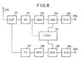
- Fig. 8 is a block diagram of a transmission and reception equipment of a mobile station according to the present invention.
- the reception signal that was received to an antenna 130 and passed through an antenna shared unit 131 (indicated by DUP) is inputted to a receiving circuit 132 (indicated by RX) which performs frequency conversion, band limit, amplification and so on.
- a portion of the output of the receiving circuit 132 is demodulated and discriminated in a demodulating circuit 133 (indicated by DEM), and then separated into a preamble signal, an information signal and a postamble signal by a demultiplexer 134 (indicated by DMX).
- the information signal is inputted to a digital/analog converter 135 (indicated by D/A), and an analog voice signal is obtained in an output terminal 550.
- the demultiplexer 134 outputs a control signal to a control circuit 136 (indicated by CONT), which measures the output signal levels of the receiving circuit 132.
- the control circuit 136 compares the reception levels measured corresponding to the postamble signals P1 and P2, and assigns the postamble signal higher in reception level. That is, a signal that assigns an antenna from which the postamble signal of higher reception level is transmitted is stored as an antenna-selection control signal.
- a transmission analog voice signal inputted to an input terminal 600 is converted into a digital signal by an analog/digital converter 140 (indicated by A/D), and then multiplexed by a multiplexer 139 (indicated by MUX), together with a preamble signal and the antenna-selection control signal stored in the control circuit 136, and outputted to a modulating circuit 138 (indicated by MOD).
- the output of the modulating circuit 138 is inputted to a transmitting circuit 137 (indicated by TX) which performs amplification, frequency conversion and the like, and transmitted through the antenna shared unit 131 from the antenna 130.
- TX transmitting circuit
- the transmission to the mobile station from the base station is a transmitting-antenna switching diversity method.
Description
Claims (5)
- A diversity transmission and reception equipment (96) which performs digital communications with a transmission and reception equipment (90) having a plurality of antennae (91, 92), said transmission and reception equipment (90) transmitting a frame signal from said plurality of antennae (91, 92) to said diversity transmission and reception equipment (96), whereby said frame signal includes at least a first signal interval (81) which is transmitted from one antenna selected from said plurality of antennae (91, 92) and a second signal interval (82) which is transmitted with time division from said plurality of antennae (91, 92) in a predetermined sequence, characterised in that
said diversity transmission and reception equipment (96) has a single antenna (99) and comprises:a receiving part (98) for receiving each of the signals of said second signal interval (82) transmitted from said plurality of antennae (91, 92) and received by said single antenna (99), the receiving part (98) having level comparing means (181) for detecting a signal of highest level from said received signals of said second signal interval (82) and transmitting said signal of highest level as a selection control signal (83); anda transmitting part (97) having a selection-control signal transmitting part (171) to which said selection control signal (83) is inputted, the selection control signal (83) being transmitted through said single antenna (99) to said transmission and reception equipment (90) having a plurality of antennae (91, 92). - A diversity transmission and reception equipment as set forth in claim 1, wherein said diversity transmission and reception equipment (96) is provided in a mobile station, and said transmission and reception equipment (90) having a plurality of antennae (91, 92) is provided in a base station.
- A diversity transmission and reception method wherein digital communications are performed between a first transmission and reception equipment (90) having a plurality of antennae (91, 92) and a second transmission and reception equipment (96), the method comprising:
transmitting a frame signal from said first transmission and reception equipment (90), the frame signal including at least a first signal interval (81) which is transmitted from one antenna selected from said plurality of antennae (91, 92) and a second signal interval (82) which is transmitted with time division from said plurality of antennae (91, 92) in a predetermined sequence;
characterised in that said second transmission and reception equipment (96) uses a single antenna (99) and the method includes the further steps of:discriminating signals of said second signal interval (82) of said frame signal transmitted from said first transmission and reception equipment (90), by said second transmission and reception equipment (96), and transmitting an optimally received signal information as a selection control signal (83) from said second transmission and reception equipment (96);selecting an antenna for reception from said plurality of antennae (91, 92) of said first transmission and reception equipment (90) by diversity antenna selection, and selecting an antenna for transmission from said plurality of antennae (91, 92) of said first transmission and reception equipment (90) by reception of said selection control signal (83) transmitted from said second transmission and reception equipment (96). - A diversity transmission and reception method as set forth in claim 3, wherein said second signal interval (82) of said frame signal is provided after said first signal interval (81).
- A diversity transmission and reception method as set forth in claim 3, wherein said first transmission and reception equipment (90) uses a plurality of antennae (91, 92) which are provided in a base station, and said second transmission and reception equipment (96) having a single antenna (99) is provided in a mobile station.
Applications Claiming Priority (7)
| Application Number | Priority Date | Filing Date | Title |
|---|---|---|---|
| JP25660288 | 1988-10-12 | ||
| JP256602/88 | 1988-10-12 | ||
| JP63256603A JP2735586B2 (en) | 1988-10-12 | 1988-10-12 | Diversity wireless communication method and wireless device using diversity wireless communication method |
| JP256603/88 | 1988-10-12 | ||
| JP138010/89 | 1989-05-31 | ||
| JP1138010A JP2746658B2 (en) | 1988-10-12 | 1989-05-31 | Antenna selection diversity radio |
| EP89310302A EP0364190B1 (en) | 1988-10-12 | 1989-10-09 | Diversity transmission and reception method and equipment |
Related Parent Applications (2)
| Application Number | Title | Priority Date | Filing Date |
|---|---|---|---|
| EP89310302A Division EP0364190B1 (en) | 1988-10-12 | 1989-10-09 | Diversity transmission and reception method and equipment |
| EP89310302.8 Division | 1989-10-09 |
Publications (2)
| Publication Number | Publication Date |
|---|---|
| EP0582323A1 EP0582323A1 (en) | 1994-02-09 |
| EP0582323B1 true EP0582323B1 (en) | 1998-04-29 |
Family
ID=27317577
Family Applications (2)
| Application Number | Title | Priority Date | Filing Date |
|---|---|---|---|
| EP89310302A Expired - Lifetime EP0364190B1 (en) | 1988-10-12 | 1989-10-09 | Diversity transmission and reception method and equipment |
| EP93116246A Expired - Lifetime EP0582323B1 (en) | 1988-10-12 | 1989-10-09 | Diversity transmission and reception method and equipment |
Family Applications Before (1)
| Application Number | Title | Priority Date | Filing Date |
|---|---|---|---|
| EP89310302A Expired - Lifetime EP0364190B1 (en) | 1988-10-12 | 1989-10-09 | Diversity transmission and reception method and equipment |
Country Status (5)
| Country | Link |
|---|---|
| US (1) | US5097484A (en) |
| EP (2) | EP0364190B1 (en) |
| CA (1) | CA2000321C (en) |
| DE (2) | DE68928660T2 (en) |
| FI (1) | FI894821A (en) |
Families Citing this family (137)
| Publication number | Priority date | Publication date | Assignee | Title |
|---|---|---|---|---|
| US5708833A (en) | 1993-04-27 | 1998-01-13 | Norand Corporation | Antenna cap, antenna connectors and telephone line connectors for computer devices utilizing radio and modem cards |
| US6431451B1 (en) * | 1991-02-25 | 2002-08-13 | Intermec Ip Corp. | Hand-held data capture system with interchangeable modules |
| US5243598A (en) * | 1991-04-02 | 1993-09-07 | Pactel Corporation | Microcell system in digital cellular |
| US5504936A (en) * | 1991-04-02 | 1996-04-02 | Airtouch Communications Of California | Microcells for digital cellular telephone systems |
| US5285469A (en) * | 1991-06-03 | 1994-02-08 | Omnipoint Data Corporation | Spread spectrum wireless telephone system |
| GB2262863B (en) * | 1991-12-23 | 1995-06-21 | Motorola Ltd | Radio communications apparatus with diversity |
| DE4213879A1 (en) * | 1992-04-28 | 1993-11-04 | Bosch Gmbh Robert | COMMUNICATION SYSTEM FOR DATA TRANSFER FROM A MOVING VEHICLE TO A FIXED BEAK |
| DE4213881A1 (en) * | 1992-04-28 | 1993-11-04 | Bosch Gmbh Robert | BIDIRECTIONAL DATA TRANSMISSION SYSTEM BETWEEN A BEAK AND A VEHICLE |
| DE4213882A1 (en) * | 1992-04-28 | 1993-11-04 | Bosch Gmbh Robert | DEVICE OF A VEHICLE FOR DATA TRANSFER TO A FIXED BAKE AND COMMUNICATION SYSTEM FORMED WITH IT |
| US5369801A (en) * | 1992-09-25 | 1994-11-29 | Northern Telecom Limited | Antenna diversity reception in wireless personal communications |
| US5504779A (en) * | 1992-12-04 | 1996-04-02 | Reliance Electric Industrial Company | Redundancy modem |
| US5325403A (en) * | 1992-12-09 | 1994-06-28 | Motorola, Inc. | Method and apparatus for dual-channel diversity reception of a radio signal |
| DE4303355A1 (en) * | 1993-02-05 | 1994-08-11 | Philips Patentverwaltung | Radio system |
| US7469150B2 (en) * | 1993-04-27 | 2008-12-23 | Broadcom Corporation | Radio card having independent antenna interface supporting antenna diversity |
| US6928302B1 (en) | 1993-04-27 | 2005-08-09 | Broadcom Corporation | Radio card having independent antenna interface supporting antenna diversity |
| US7119750B2 (en) * | 1993-04-27 | 2006-10-10 | Broadcom Corporation | Radio transceiver card communicating in a plurality of frequency bands |
| US5507035A (en) * | 1993-04-30 | 1996-04-09 | International Business Machines Corporation | Diversity transmission strategy in mobile/indoor cellula radio communications |
| DE4322863C2 (en) * | 1993-07-09 | 1995-05-18 | Ant Nachrichtentech | Cellular antenna system |
| US5459873A (en) * | 1993-08-21 | 1995-10-17 | Motorola, Inc. | Method and communication system for improved channel scanning and link establishment determinations |
| CN1093345C (en) * | 1993-09-28 | 2002-10-23 | 株式会社东芝 | Selective diversity system |
| JP3989532B2 (en) * | 1993-09-30 | 2007-10-10 | スカイワークス ソリューションズ,インコーポレイテッド | Multi-antenna home base for digital cordless telephones |
| US6005856A (en) * | 1993-11-01 | 1999-12-21 | Omnipoint Corporation | Communication protocol for spread spectrum wireless communication system |
| US6094575A (en) * | 1993-11-01 | 2000-07-25 | Omnipoint Corporation | Communication system and method |
| US6088590A (en) * | 1993-11-01 | 2000-07-11 | Omnipoint Corporation | Method and system for mobile controlled handoff and link maintenance in spread spectrum communication |
| US5960344A (en) * | 1993-12-20 | 1999-09-28 | Norand Corporation | Local area network having multiple channel wireless access |
| US5546397A (en) * | 1993-12-20 | 1996-08-13 | Norand Corporation | High reliability access point for wireless local area network |
| JP2876517B2 (en) * | 1994-02-16 | 1999-03-31 | 松下電器産業株式会社 | CDMA / TDD base station apparatus, CDMA / TDD mobile station apparatus, CDMA / TDD wireless communication system, and CDMA / TDD wireless communication method |
| GB2291271B (en) | 1994-07-09 | 1998-05-13 | Northern Telecom Ltd | Communications antenna structure |
| US5614914A (en) * | 1994-09-06 | 1997-03-25 | Interdigital Technology Corporation | Wireless telephone distribution system with time and space diversity transmission for determining receiver location |
| US5953370A (en) | 1994-09-09 | 1999-09-14 | Omnipoint Corporation | Apparatus for receiving and correlating a spread spectrum signal |
| US5742583A (en) * | 1994-11-03 | 1998-04-21 | Omnipoint Corporation | Antenna diversity techniques |
| KR960027576A (en) * | 1994-12-01 | 1996-07-22 | 리차드 탤런 | Wireless Signal Scanning and Targeting System for Land Mobile Wireless Base Sites |
| US5701596A (en) * | 1994-12-01 | 1997-12-23 | Radio Frequency Systems, Inc. | Modular interconnect matrix for matrix connection of a plurality of antennas with a plurality of radio channel units |
| US5581260A (en) * | 1995-01-27 | 1996-12-03 | Hazeltine Corporation | Angular diversity/spaced diversity cellular antennas and methods |
| CA2164169A1 (en) * | 1995-01-31 | 1996-08-01 | Sheldon Kent Meredith | Radio signal scanning and targeting system for use in land mobile radio base sites |
| JP2751869B2 (en) * | 1995-04-28 | 1998-05-18 | 日本電気株式会社 | Transmit diversity method |
| JPH11505395A (en) * | 1995-05-18 | 1999-05-18 | オーラ コミュニケーションズ,インコーポレイテッド | Short-distance magnetic communication system |
| US5912925A (en) | 1995-05-18 | 1999-06-15 | Aura Communications, Inc. | Diversity circuit for magnetic communication system |
| US6356607B1 (en) | 1995-06-05 | 2002-03-12 | Omnipoint Corporation | Preamble code structure and detection method and apparatus |
| US5959980A (en) * | 1995-06-05 | 1999-09-28 | Omnipoint Corporation | Timing adjustment control for efficient time division duplex communication |
| US5689502A (en) * | 1995-06-05 | 1997-11-18 | Omnipoint Corporation | Efficient frequency division duplex communication system with interleaved format and timing adjustment control |
| US5745484A (en) * | 1995-06-05 | 1998-04-28 | Omnipoint Corporation | Efficient communication system using time division multiplexing and timing adjustment control |
| US5802046A (en) * | 1995-06-05 | 1998-09-01 | Omnipoint Corporation | Efficient time division duplex communication system with interleaved format and timing adjustment control |
| US6041046A (en) * | 1995-07-14 | 2000-03-21 | Omnipoint Corporation | Cyclic time hopping in time division multiple access communication system |
| US5732076A (en) * | 1995-10-26 | 1998-03-24 | Omnipoint Corporation | Coexisting communication systems |
| US5870681A (en) * | 1995-12-28 | 1999-02-09 | Lucent Technologies, Inc. | Self-steering antenna array |
| US5669060A (en) * | 1996-03-04 | 1997-09-16 | Telefonaktiebolaget L M Ericsson (Publ) | Method and apparatus for enhancing call set-up and handoff quality |
| JP2947157B2 (en) * | 1996-03-07 | 1999-09-13 | 日本電気株式会社 | Transmission space diversity control method and transmission space diversity apparatus |
| US5697066A (en) * | 1996-03-07 | 1997-12-09 | The Trustees Of Columbia University | Media access protocol for packet access within a radio cell |
| US6697415B1 (en) * | 1996-06-03 | 2004-02-24 | Broadcom Corporation | Spread spectrum transceiver module utilizing multiple mode transmission |
| US6006075A (en) | 1996-06-18 | 1999-12-21 | Telefonaktiebolaget L M Ericsson (Publ) | Method and apparatus for transmitting communication signals using transmission space diversity and frequency diversity |
| US6243565B1 (en) * | 1996-06-18 | 2001-06-05 | Telefonaktiebolaget Lm Ericsson (Publ) | Method and apparatus for transmitting communication signals using frequency and polarization diversity |
| US6198925B1 (en) | 1996-08-30 | 2001-03-06 | Cellco Partnership | Method and apparatus for intelligent microcell and antenna selection in digital cellular telephone systems |
| US6011487A (en) * | 1996-09-17 | 2000-01-04 | Ncr Corporation | System and method of locating wireless devices |
| CA2188845A1 (en) * | 1996-10-25 | 1998-04-25 | Stephen Ross Todd | Diversity Antenna Selection |
| US6141373A (en) | 1996-11-15 | 2000-10-31 | Omnipoint Corporation | Preamble code structure and detection method and apparatus |
| US6032033A (en) * | 1996-12-03 | 2000-02-29 | Nortel Networks Corporation | Preamble based selection diversity in a time division multiple access radio system using digital demodulation |
| US5960046A (en) * | 1996-12-03 | 1999-09-28 | Northern Telecom Limited | Preamble based selection diversity in a time division multiple access radio system |
| US5842118A (en) * | 1996-12-18 | 1998-11-24 | Micron Communications, Inc. | Communication system including diversity antenna queuing |
| US6289209B1 (en) | 1996-12-18 | 2001-09-11 | Micron Technology, Inc. | Wireless communication system, radio frequency communications system, wireless communications method, radio frequency communications method |
| JPH10285056A (en) * | 1997-03-31 | 1998-10-23 | Nec Corp | Antenna changeover device |
| US6085076A (en) * | 1997-04-07 | 2000-07-04 | Omnipoint Corporation | Antenna diversity for wireless communication system |
| JP3290926B2 (en) * | 1997-07-04 | 2002-06-10 | 松下電器産業株式会社 | Transmit diversity device |
| US6341124B1 (en) | 1998-03-13 | 2002-01-22 | Telefonaktiebolaget Lm Ericsson | Accommodating packet data loss at base stations interfacing between a packet switched network and a CDMA macrodiversity network |
| JP2002026796A (en) | 1998-04-07 | 2002-01-25 | Matsushita Electric Ind Co Ltd | Wireless communication equipment and wireless communication system |
| FI981377A (en) * | 1998-04-24 | 1999-10-25 | Nokia Networks Oy | Sändarantenndiversitet |
| DE19820460C2 (en) * | 1998-05-07 | 2000-03-30 | Siemens Ag | Cellular base station with adaptive antenna |
| DE19824152C2 (en) * | 1998-05-29 | 2003-06-05 | Siemens Ag | Method and radio station for signal transmission in a radio communication system |
| KR20000002504A (en) * | 1998-06-20 | 2000-01-15 | 윤종용 | Selective transmitting diversity device of mobile communication system and method thereof |
| BR9906705A (en) * | 1998-08-20 | 2000-09-05 | Samsung Electronics Co Ltd | Process and channel communication device for a mobile communication system using transmitting antenna diversity, process for selecting, on a mobile station, a transmitting antenna on a base station on a mobile communication system using transmitting antenna diversity, and, base station device |
| US6330458B1 (en) * | 1998-08-31 | 2001-12-11 | Lucent Technologies Inc. | Intelligent antenna sub-sector switching for time slotted systems |
| JP3380481B2 (en) * | 1998-12-17 | 2003-02-24 | 松下電器産業株式会社 | Base station equipment |
| GB2347828B (en) * | 1999-03-05 | 2004-05-19 | Internat Mobile Satellite Orga | Communication methods and apparatus |
| JP3667549B2 (en) * | 1999-03-29 | 2005-07-06 | 日本電気株式会社 | Diversity receiver |
| SE517197C2 (en) | 1999-04-15 | 2002-05-07 | Ericsson Telefon Ab L M | Adaptive sector classification |
| US6947469B2 (en) | 1999-05-07 | 2005-09-20 | Intel Corporation | Method and Apparatus for wireless spread spectrum communication with preamble processing period |
| JP4232879B2 (en) * | 1999-09-02 | 2009-03-04 | パナソニック株式会社 | Communication device |
| DE10014352A1 (en) * | 2000-03-24 | 2001-10-04 | Elan Schaltelemente Gmbh & Co | Arrangement for transmitting security-relevant data over radio path has second antenna and redundant evaluation device per station with both antennae being connected to transmitter and/or receiver |
| ATE450131T1 (en) | 2000-08-03 | 2009-12-15 | Infineon Technologies Ag | DYNAMIC RECONFIGURABLE UNIVERSAL TRANSMITTER SYSTEM |
| KR100614410B1 (en) * | 2000-12-01 | 2006-08-18 | 주식회사 케이티 | The Apparatus and Method for Detecting the Signals of Space-Time Coding based Transmit Diversity |
| US20020132583A1 (en) * | 2001-03-19 | 2002-09-19 | Jelinek Lenka M. | Antenna system, software and methods for locating an object |
| US7103382B2 (en) * | 2001-07-10 | 2006-09-05 | Kyocera Wireless Corp. | System and method for receiving and transmitting information in a multipath environment |
| JP4130191B2 (en) * | 2004-01-28 | 2008-08-06 | 三洋電機株式会社 | Transmitter |
| TWI253811B (en) * | 2004-01-28 | 2006-04-21 | Sanyo Electric Co | Transmission method and device, reception method and device, and communication system using the same |
| US7193562B2 (en) * | 2004-11-22 | 2007-03-20 | Ruckus Wireless, Inc. | Circuit board having a peripheral antenna apparatus with selectable antenna elements |
| US7652632B2 (en) * | 2004-08-18 | 2010-01-26 | Ruckus Wireless, Inc. | Multiband omnidirectional planar antenna apparatus with selectable elements |
| US7696946B2 (en) * | 2004-08-18 | 2010-04-13 | Ruckus Wireless, Inc. | Reducing stray capacitance in antenna element switching |
| US7880683B2 (en) | 2004-08-18 | 2011-02-01 | Ruckus Wireless, Inc. | Antennas with polarization diversity |
| US7965252B2 (en) * | 2004-08-18 | 2011-06-21 | Ruckus Wireless, Inc. | Dual polarization antenna array with increased wireless coverage |
| US7292198B2 (en) * | 2004-08-18 | 2007-11-06 | Ruckus Wireless, Inc. | System and method for an omnidirectional planar antenna apparatus with selectable elements |
| US7933628B2 (en) * | 2004-08-18 | 2011-04-26 | Ruckus Wireless, Inc. | Transmission and reception parameter control |
| US8031129B2 (en) | 2004-08-18 | 2011-10-04 | Ruckus Wireless, Inc. | Dual band dual polarization antenna array |
| US7899497B2 (en) * | 2004-08-18 | 2011-03-01 | Ruckus Wireless, Inc. | System and method for transmission parameter control for an antenna apparatus with selectable elements |
| TWI391018B (en) * | 2004-11-05 | 2013-03-21 | Ruckus Wireless Inc | Throughput enhancement by acknowledgment suppression |
| US7505447B2 (en) * | 2004-11-05 | 2009-03-17 | Ruckus Wireless, Inc. | Systems and methods for improved data throughput in communications networks |
| US8638708B2 (en) * | 2004-11-05 | 2014-01-28 | Ruckus Wireless, Inc. | MAC based mapping in IP based communications |
| US8619662B2 (en) * | 2004-11-05 | 2013-12-31 | Ruckus Wireless, Inc. | Unicast to multicast conversion |
| US8792414B2 (en) * | 2005-07-26 | 2014-07-29 | Ruckus Wireless, Inc. | Coverage enhancement using dynamic antennas |
| US7358912B1 (en) | 2005-06-24 | 2008-04-15 | Ruckus Wireless, Inc. | Coverage antenna apparatus with selectable horizontal and vertical polarization elements |
| US7893882B2 (en) | 2007-01-08 | 2011-02-22 | Ruckus Wireless, Inc. | Pattern shaping of RF emission patterns |
| US7646343B2 (en) * | 2005-06-24 | 2010-01-12 | Ruckus Wireless, Inc. | Multiple-input multiple-output wireless antennas |
| US20060237384A1 (en) * | 2005-04-20 | 2006-10-26 | Eric Neumann | Track unit with removable partitions |
| GB2426407B (en) * | 2005-05-19 | 2010-01-06 | Roke Manor Research | Transceiver antannae arrangement |
| US7893813B2 (en) * | 2005-07-28 | 2011-02-22 | Intermec Ip Corp. | Automatic data collection device, method and article |
| US8199689B2 (en) * | 2005-09-21 | 2012-06-12 | Intermec Ip Corp. | Stochastic communication protocol method and system for radio frequency identification (RFID) tags based on coalition formation, such as for tag-to-tag communication |
| CN101322346A (en) | 2005-12-01 | 2008-12-10 | 鲁库斯无线公司 | On-demand services by wireless base station virtualization |
| US8120461B2 (en) * | 2006-04-03 | 2012-02-21 | Intermec Ip Corp. | Automatic data collection device, method and article |
| US7788703B2 (en) * | 2006-04-24 | 2010-08-31 | Ruckus Wireless, Inc. | Dynamic authentication in secured wireless networks |
| US9071583B2 (en) * | 2006-04-24 | 2015-06-30 | Ruckus Wireless, Inc. | Provisioned configuration for automatic wireless connection |
| US9769655B2 (en) | 2006-04-24 | 2017-09-19 | Ruckus Wireless, Inc. | Sharing security keys with headless devices |
| US7639106B2 (en) * | 2006-04-28 | 2009-12-29 | Ruckus Wireless, Inc. | PIN diode network for multiband RF coupling |
| US20070293178A1 (en) * | 2006-05-23 | 2007-12-20 | Darin Milton | Antenna Control |
| US8002173B2 (en) * | 2006-07-11 | 2011-08-23 | Intermec Ip Corp. | Automatic data collection device, method and article |
| US7579955B2 (en) * | 2006-08-11 | 2009-08-25 | Intermec Ip Corp. | Device and method for selective backscattering of wireless communications signals |
| US8670725B2 (en) | 2006-08-18 | 2014-03-11 | Ruckus Wireless, Inc. | Closed-loop automatic channel selection |
| JP5235342B2 (en) | 2007-06-22 | 2013-07-10 | キヤノン株式会社 | Communication apparatus, control method, and program |
| US8547899B2 (en) | 2007-07-28 | 2013-10-01 | Ruckus Wireless, Inc. | Wireless network throughput enhancement through channel aware scheduling |
| US8355343B2 (en) | 2008-01-11 | 2013-01-15 | Ruckus Wireless, Inc. | Determining associations in a mesh network |
| US8217843B2 (en) * | 2009-03-13 | 2012-07-10 | Ruckus Wireless, Inc. | Adjustment of radiation patterns utilizing a position sensor |
| US8698675B2 (en) | 2009-05-12 | 2014-04-15 | Ruckus Wireless, Inc. | Mountable antenna elements for dual band antenna |
| CN102687418B (en) * | 2009-11-13 | 2016-08-17 | 皇家飞利浦电子股份有限公司 | System and method and communication unit for the physiological data that communicates |
| US9999087B2 (en) * | 2009-11-16 | 2018-06-12 | Ruckus Wireless, Inc. | Determining role assignment in a hybrid mesh network |
| US9979626B2 (en) | 2009-11-16 | 2018-05-22 | Ruckus Wireless, Inc. | Establishing a mesh network with wired and wireless links |
| US8918062B2 (en) | 2009-12-08 | 2014-12-23 | Qualcomm Incorporated | Combined intelligent receive diversity (IRD) and mobile transmit diversity (MTD) with independent antenna switching for uplink and downlink |
| US9407012B2 (en) | 2010-09-21 | 2016-08-02 | Ruckus Wireless, Inc. | Antenna with dual polarization and mountable antenna elements |
| EP2705429B1 (en) | 2011-05-01 | 2016-07-06 | Ruckus Wireless, Inc. | Remote cable access point reset |
| US8756668B2 (en) | 2012-02-09 | 2014-06-17 | Ruckus Wireless, Inc. | Dynamic PSK for hotspots |
| US10186750B2 (en) | 2012-02-14 | 2019-01-22 | Arris Enterprises Llc | Radio frequency antenna array with spacing element |
| US9634403B2 (en) | 2012-02-14 | 2017-04-25 | Ruckus Wireless, Inc. | Radio frequency emission pattern shaping |
| EP2828982B1 (en) | 2012-03-23 | 2017-02-08 | Sony Mobile Communications AB | Antenna swapping methods including comparing performance characteristics of first and second antennas, and related portable electronic devices |
| US9092610B2 (en) | 2012-04-04 | 2015-07-28 | Ruckus Wireless, Inc. | Key assignment for a brand |
| US9570799B2 (en) | 2012-09-07 | 2017-02-14 | Ruckus Wireless, Inc. | Multiband monopole antenna apparatus with ground plane aperture |
| US9007970B2 (en) | 2012-10-11 | 2015-04-14 | Sony Corporation | Antenna swapping methods including repeatedly swapping between antennas, and related wireless electronic devices |
| CN105051975B (en) | 2013-03-15 | 2019-04-19 | 艾锐势有限责任公司 | Low-frequency band reflector for double frequency-band directional aerial |
| US9893715B2 (en) * | 2013-12-09 | 2018-02-13 | Shure Acquisition Holdings, Inc. | Adaptive self-tunable antenna system and method |
| CN109257082A (en) * | 2017-07-14 | 2019-01-22 | 中兴通讯股份有限公司 | A kind of antenna switching handling method, apparatus and system |
| US11722412B1 (en) | 2020-09-28 | 2023-08-08 | Amazon Technologies, Inc. | Dynamically managing connection parameters among multiple computing devices |
Family Cites Families (9)
| Publication number | Priority date | Publication date | Assignee | Title |
|---|---|---|---|---|
| NL6408627A (en) * | 1964-07-29 | 1966-01-31 | ||
| US3375516A (en) * | 1967-05-26 | 1968-03-26 | Navy Usa | Dual antenna system for transponder beacon devices |
| US4041397A (en) * | 1976-04-28 | 1977-08-09 | The United States Of America As Represented By The Secretary Of The Navy | Satellite up link diversity switch |
| US4317218A (en) * | 1980-03-26 | 1982-02-23 | General Electric Company | Arrangement for remote control of repeater stations |
| US4383332A (en) * | 1980-11-21 | 1983-05-10 | Bell Telephone Laboratories, Incorporated | High capacity digital mobile radio system |
| US4513412A (en) * | 1983-04-25 | 1985-04-23 | At&T Bell Laboratories | Time division adaptive retransmission technique for portable radio telephones |
| DE3678887D1 (en) * | 1985-09-17 | 1991-05-29 | Siemens Ag | NEWS TRANSMISSION SYSTEM FOR ELECTROMAGNETIC WAVES. |
| JPH07120977B2 (en) * | 1987-09-16 | 1995-12-20 | 松下電器産業株式会社 | Optical coupling device |
| US4953197A (en) * | 1988-12-08 | 1990-08-28 | International Mobile Machines Corporation | Combination spatial diversity system |
-
1989
- 1989-10-05 US US07/417,559 patent/US5097484A/en not_active Expired - Fee Related
- 1989-10-06 CA CA002000321A patent/CA2000321C/en not_active Expired - Fee Related
- 1989-10-09 EP EP89310302A patent/EP0364190B1/en not_active Expired - Lifetime
- 1989-10-09 EP EP93116246A patent/EP0582323B1/en not_active Expired - Lifetime
- 1989-10-09 DE DE68928660T patent/DE68928660T2/en not_active Expired - Fee Related
- 1989-10-09 DE DE68920257T patent/DE68920257T2/en not_active Expired - Fee Related
- 1989-10-11 FI FI894821A patent/FI894821A/en not_active Application Discontinuation
Also Published As
| Publication number | Publication date |
|---|---|
| FI894821A0 (en) | 1989-10-11 |
| CA2000321C (en) | 1994-04-05 |
| CA2000321A1 (en) | 1990-04-12 |
| DE68920257T2 (en) | 1995-08-10 |
| EP0364190B1 (en) | 1994-12-28 |
| DE68920257D1 (en) | 1995-02-09 |
| DE68928660D1 (en) | 1998-06-04 |
| FI894821A (en) | 1990-04-13 |
| EP0364190A3 (en) | 1992-03-04 |
| EP0582323A1 (en) | 1994-02-09 |
| US5097484A (en) | 1992-03-17 |
| DE68928660T2 (en) | 1998-12-24 |
| EP0364190A2 (en) | 1990-04-18 |
Similar Documents
| Publication | Publication Date | Title |
|---|---|---|
| EP0582323B1 (en) | Diversity transmission and reception method and equipment | |
| US5390166A (en) | Method for recovering a data signal using diversity in a radio frequency, time division multiple access communication system | |
| US7379749B2 (en) | Radio terminal apparatus and reception operation control program thereof | |
| EP0440239B1 (en) | Antenna selection diversity reception apparatus | |
| US6185435B1 (en) | Radio communication apparatus for communicating with a plurality of different communication systems | |
| EP0991203B1 (en) | Communication terminal apparatus for a CDMA/TDD system using signals having a TDMA frame structure | |
| CA1246148A (en) | Radio system wherein transmission power is varied according to transmission quality | |
| CA2137386C (en) | Time division multiple access mobile wireless telecommunication system | |
| US20080051148A1 (en) | Radio base station apparatus, radio terminal apparatus, mobile communication system, and reception operation control program | |
| US6553078B1 (en) | Antenna switching diversity | |
| US5210752A (en) | Radio tele-communication system using multichannel access scheme | |
| EP1044516B1 (en) | Tstd transmitter for limiting transmission power of antenna and controlling method thereof for base station in mobile communication system | |
| US6052602A (en) | Method and apparatus for selecting a base station based on a timing value obtained from a system timing signal | |
| US6738365B1 (en) | Method of improving connection quality and system capacity, and a cellular radio system | |
| WO1998012678A2 (en) | Method of facilitating transmission level measurement, and base station | |
| US6885650B1 (en) | Method, radio communications system and mobile station for information transmission | |
| JP2656758B2 (en) | Channel switching method between wireless zones in mobile communication system | |
| JP2735586B2 (en) | Diversity wireless communication method and wireless device using diversity wireless communication method | |
| EP0479741B1 (en) | Method for antenna selection in a mobile radio communication system | |
| JP2746658B2 (en) | Antenna selection diversity radio | |
| EP0440186B1 (en) | Signal control apparatus capable of readily changing an apparatus output signal | |
| JPH0560286B2 (en) | ||
| JP3149917B2 (en) | Diversity method | |
| CN1242118A (en) | Method of improving connection quality and system capacity, and a cellular radio system | |
| EP1053602A1 (en) | Radio receiving apparatus with switched diversity |
Legal Events
| Date | Code | Title | Description |
|---|---|---|---|
| PUAI | Public reference made under article 153(3) epc to a published international application that has entered the european phase |
Free format text: ORIGINAL CODE: 0009012 |
|
| AC | Divisional application: reference to earlier application |
Ref document number: 364190 Country of ref document: EP |
|
| AK | Designated contracting states |
Kind code of ref document: A1 Designated state(s): CH DE FR GB IT LI NL SE |
|
| RIN1 | Information on inventor provided before grant (corrected) |
Inventor name: AKAIWA, YOSHIHIKO |
|
| 17P | Request for examination filed |
Effective date: 19940221 |
|
| 17Q | First examination report despatched |
Effective date: 19960807 |
|
| GRAG | Despatch of communication of intention to grant |
Free format text: ORIGINAL CODE: EPIDOS AGRA |
|
| GRAG | Despatch of communication of intention to grant |
Free format text: ORIGINAL CODE: EPIDOS AGRA |
|
| GRAH | Despatch of communication of intention to grant a patent |
Free format text: ORIGINAL CODE: EPIDOS IGRA |
|
| GRAH | Despatch of communication of intention to grant a patent |
Free format text: ORIGINAL CODE: EPIDOS IGRA |
|
| GRAA | (expected) grant |
Free format text: ORIGINAL CODE: 0009210 |
|
| AC | Divisional application: reference to earlier application |
Ref document number: 364190 Country of ref document: EP |
|
| AK | Designated contracting states |
Kind code of ref document: B1 Designated state(s): CH DE FR GB IT LI NL SE |
|
| REG | Reference to a national code |
Ref country code: CH Ref legal event code: EP |
|
| REF | Corresponds to: |
Ref document number: 68928660 Country of ref document: DE Date of ref document: 19980604 |
|
| REG | Reference to a national code |
Ref country code: CH Ref legal event code: NV Representative=s name: E. BLUM & CO. PATENTANWAELTE |
|
| ITF | It: translation for a ep patent filed |
Owner name: UFFICIO BREVETTI RAPISARDI S.R.L. |
|
| ET | Fr: translation filed | ||
| PGFP | Annual fee paid to national office [announced via postgrant information from national office to epo] |
Ref country code: GB Payment date: 19980924 Year of fee payment: 10 |
|
| PGFP | Annual fee paid to national office [announced via postgrant information from national office to epo] |
Ref country code: FR Payment date: 19980930 Year of fee payment: 10 |
|
| PGFP | Annual fee paid to national office [announced via postgrant information from national office to epo] |
Ref country code: DE Payment date: 19981006 Year of fee payment: 10 |
|
| PGFP | Annual fee paid to national office [announced via postgrant information from national office to epo] |
Ref country code: CH Payment date: 19981007 Year of fee payment: 10 Ref country code: SE Payment date: 19981007 Year of fee payment: 10 |
|
| PGFP | Annual fee paid to national office [announced via postgrant information from national office to epo] |
Ref country code: NL Payment date: 19981008 Year of fee payment: 10 |
|
| PLBE | No opposition filed within time limit |
Free format text: ORIGINAL CODE: 0009261 |
|
| STAA | Information on the status of an ep patent application or granted ep patent |
Free format text: STATUS: NO OPPOSITION FILED WITHIN TIME LIMIT |
|
| 26N | No opposition filed | ||
| PG25 | Lapsed in a contracting state [announced via postgrant information from national office to epo] |
Ref country code: GB Free format text: LAPSE BECAUSE OF NON-PAYMENT OF DUE FEES Effective date: 19991009 |
|
| PG25 | Lapsed in a contracting state [announced via postgrant information from national office to epo] |
Ref country code: SE Free format text: THE PATENT HAS BEEN ANNULLED BY A DECISION OF A NATIONAL AUTHORITY Effective date: 19991030 |
|
| PG25 | Lapsed in a contracting state [announced via postgrant information from national office to epo] |
Ref country code: LI Free format text: LAPSE BECAUSE OF NON-PAYMENT OF DUE FEES Effective date: 19991031 Ref country code: CH Free format text: LAPSE BECAUSE OF NON-PAYMENT OF DUE FEES Effective date: 19991031 |
|
| PG25 | Lapsed in a contracting state [announced via postgrant information from national office to epo] |
Ref country code: NL Free format text: LAPSE BECAUSE OF NON-PAYMENT OF DUE FEES Effective date: 20000501 |
|
| GBPC | Gb: european patent ceased through non-payment of renewal fee |
Effective date: 19991009 |
|
| REG | Reference to a national code |
Ref country code: CH Ref legal event code: PL |
|
| EUG | Se: european patent has lapsed |
Ref document number: 93116246.5 |
|
| PG25 | Lapsed in a contracting state [announced via postgrant information from national office to epo] |
Ref country code: FR Free format text: LAPSE BECAUSE OF NON-PAYMENT OF DUE FEES Effective date: 20000630 |
|
| NLV4 | Nl: lapsed or anulled due to non-payment of the annual fee |
Effective date: 20000501 |
|
| PG25 | Lapsed in a contracting state [announced via postgrant information from national office to epo] |
Ref country code: DE Free format text: LAPSE BECAUSE OF NON-PAYMENT OF DUE FEES Effective date: 20000801 |
|
| REG | Reference to a national code |
Ref country code: FR Ref legal event code: ST |
|
| PG25 | Lapsed in a contracting state [announced via postgrant information from national office to epo] |
Ref country code: IT Free format text: LAPSE BECAUSE OF NON-PAYMENT OF DUE FEES;WARNING: LAPSES OF ITALIAN PATENTS WITH EFFECTIVE DATE BEFORE 2007 MAY HAVE OCCURRED AT ANY TIME BEFORE 2007. THE CORRECT EFFECTIVE DATE MAY BE DIFFERENT FROM THE ONE RECORDED. Effective date: 20051009 |