EP0581533A2 - Stage cementer and inflation packer apparatus - Google Patents
Stage cementer and inflation packer apparatus Download PDFInfo
- Publication number
- EP0581533A2 EP0581533A2 EP93305792A EP93305792A EP0581533A2 EP 0581533 A2 EP0581533 A2 EP 0581533A2 EP 93305792 A EP93305792 A EP 93305792A EP 93305792 A EP93305792 A EP 93305792A EP 0581533 A2 EP0581533 A2 EP 0581533A2
- Authority
- EP
- European Patent Office
- Prior art keywords
- mandrel
- sleeve
- opening
- port
- cementing
- Prior art date
- Legal status (The legal status is an assumption and is not a legal conclusion. Google has not performed a legal analysis and makes no representation as to the accuracy of the status listed.)
- Withdrawn
Links
- 238000004891 communication Methods 0.000 claims description 41
- 238000012856 packing Methods 0.000 claims description 41
- 239000012530 fluid Substances 0.000 claims description 35
- 230000004044 response Effects 0.000 claims description 5
- 238000011144 upstream manufacturing Methods 0.000 claims description 2
- 238000007789 sealing Methods 0.000 description 55
- 239000004568 cement Substances 0.000 description 30
- 230000008878 coupling Effects 0.000 description 11
- 238000010168 coupling process Methods 0.000 description 11
- 238000005859 coupling reaction Methods 0.000 description 11
- 210000002445 nipple Anatomy 0.000 description 8
- 230000009471 action Effects 0.000 description 4
- 238000005553 drilling Methods 0.000 description 4
- 238000004519 manufacturing process Methods 0.000 description 4
- 238000000034 method Methods 0.000 description 4
- 230000008569 process Effects 0.000 description 4
- XLYOFNOQVPJJNP-UHFFFAOYSA-N water Substances O XLYOFNOQVPJJNP-UHFFFAOYSA-N 0.000 description 4
- XAGFODPZIPBFFR-UHFFFAOYSA-N aluminium Chemical compound [Al] XAGFODPZIPBFFR-UHFFFAOYSA-N 0.000 description 3
- 229910052782 aluminium Inorganic materials 0.000 description 3
- 230000015572 biosynthetic process Effects 0.000 description 3
- 238000005755 formation reaction Methods 0.000 description 3
- 239000000463 material Substances 0.000 description 3
- 239000003129 oil well Substances 0.000 description 3
- 230000002028 premature Effects 0.000 description 3
- 238000010008 shearing Methods 0.000 description 3
- 210000001364 upper extremity Anatomy 0.000 description 3
- 230000001681 protective effect Effects 0.000 description 2
- 230000000246 remedial effect Effects 0.000 description 2
- 150000003839 salts Chemical class 0.000 description 2
- 239000002002 slurry Substances 0.000 description 2
- 238000003466 welding Methods 0.000 description 2
- 229910000831 Steel Inorganic materials 0.000 description 1
- 238000005452 bending Methods 0.000 description 1
- 238000010276 construction Methods 0.000 description 1
- 238000005260 corrosion Methods 0.000 description 1
- 230000007797 corrosion Effects 0.000 description 1
- 239000003651 drinking water Substances 0.000 description 1
- 235000020188 drinking water Nutrition 0.000 description 1
- 238000005868 electrolysis reaction Methods 0.000 description 1
- 230000002706 hydrostatic effect Effects 0.000 description 1
- 230000006872 improvement Effects 0.000 description 1
- 229910052500 inorganic mineral Inorganic materials 0.000 description 1
- 230000003993 interaction Effects 0.000 description 1
- 239000011707 mineral Substances 0.000 description 1
- 239000003208 petroleum Substances 0.000 description 1
- 238000005086 pumping Methods 0.000 description 1
- 230000008439 repair process Effects 0.000 description 1
- 239000010959 steel Substances 0.000 description 1
- 239000000126 substance Substances 0.000 description 1
- 239000003643 water by type Substances 0.000 description 1
Images


Classifications
-
- E—FIXED CONSTRUCTIONS
- E21—EARTH DRILLING; MINING
- E21B—EARTH DRILLING, e.g. DEEP DRILLING; OBTAINING OIL, GAS, WATER, SOLUBLE OR MELTABLE MATERIALS OR A SLURRY OF MINERALS FROM WELLS
- E21B34/00—Valve arrangements for boreholes or wells
- E21B34/06—Valve arrangements for boreholes or wells in wells
- E21B34/14—Valve arrangements for boreholes or wells in wells operated by movement of tools, e.g. sleeve valves operated by pistons or wire line tools
- E21B34/142—Valve arrangements for boreholes or wells in wells operated by movement of tools, e.g. sleeve valves operated by pistons or wire line tools unsupported or free-falling elements, e.g. balls, plugs, darts or pistons
-
- E—FIXED CONSTRUCTIONS
- E21—EARTH DRILLING; MINING
- E21B—EARTH DRILLING, e.g. DEEP DRILLING; OBTAINING OIL, GAS, WATER, SOLUBLE OR MELTABLE MATERIALS OR A SLURRY OF MINERALS FROM WELLS
- E21B33/00—Sealing or packing boreholes or wells
- E21B33/10—Sealing or packing boreholes or wells in the borehole
- E21B33/12—Packers; Plugs
- E21B33/127—Packers; Plugs with inflatable sleeve
-
- E—FIXED CONSTRUCTIONS
- E21—EARTH DRILLING; MINING
- E21B—EARTH DRILLING, e.g. DEEP DRILLING; OBTAINING OIL, GAS, WATER, SOLUBLE OR MELTABLE MATERIALS OR A SLURRY OF MINERALS FROM WELLS
- E21B33/00—Sealing or packing boreholes or wells
- E21B33/10—Sealing or packing boreholes or wells in the borehole
- E21B33/13—Methods or devices for cementing, for plugging holes, crevices, or the like
- E21B33/14—Methods or devices for cementing, for plugging holes, crevices, or the like for cementing casings into boreholes
- E21B33/146—Stage cementing, i.e. discharging cement from casing at different levels
-
- E—FIXED CONSTRUCTIONS
- E21—EARTH DRILLING; MINING
- E21B—EARTH DRILLING, e.g. DEEP DRILLING; OBTAINING OIL, GAS, WATER, SOLUBLE OR MELTABLE MATERIALS OR A SLURRY OF MINERALS FROM WELLS
- E21B33/00—Sealing or packing boreholes or wells
- E21B33/10—Sealing or packing boreholes or wells in the borehole
- E21B33/13—Methods or devices for cementing, for plugging holes, crevices, or the like
- E21B33/14—Methods or devices for cementing, for plugging holes, crevices, or the like for cementing casings into boreholes
- E21B33/16—Methods or devices for cementing, for plugging holes, crevices, or the like for cementing casings into boreholes using plugs for isolating cement charge; Plugs therefor
Definitions
- This invention relates to a cementing tool apparatus used in downhole cementing of well casing, and more particularly to a stage cementer and inflation packer combination which allows cementing above the packer after setting thereof.
- oil well cementing is the process of mixing a cement-water slurry and pumping it down through steel casing to critical points located in the annulus around the casing, in the open hole below, or in fractured formations.
- Cementing a well protects possible production zones behind the casing against salt water flow and protects the casing against corrosion from subsurface mineral waters and electrolysis from outside. Cementing also eliminates the danger of fresh drinking water and recreational water supply strata from being contaminated by oil or salt water flow through the borehole from formations containing these substances. It further prevents oil well blowouts and fires caused by high pressure gas zones behind the casing and prevents collapse of the casing from high external pressures which can build up under ground.
- a cementing operation for protection against the above-described downhole condition is called primary cementing.
- Secondary cementing includes the cementing processes used in a well during its productive life, such as remedial cementing and repairs to existing cemented areas.
- the present invention is generally useful in both primary and secondary or remedial cementing. In the early days of oil field production, when wells were all relatively shallow, cementing was accomplished by flowing the cement slurry down the casing and back up the outside of the casing in the annulus between the casing and the borehole wall.
- Multiple stage cementing is achieved by placing cementing tools, which are primarily valved ports, in the casing or between joints of casing at one or more locations in the borehole; flowing cement through the bottom of the casing, up the annulus to the lowest cementing tool in the well; closing off the bottom and opening the cementing tool; and then flowing cement through the cement tool up the annulus to the next upper stage, and repeating this process until all of the stages of cementing are completed.
- cementing tools which are primarily valved ports
- Some prior art cementing tools used for multi-stage cementing have two internal sleeves, both of which are shear-pinned initially in an upper position, closing the cementing ports in the tool.
- a plug is flowed down the casing and seated on the lower sleeve. Fluid pressure is then increased in the casing until sufficient force is developed on the plug and sleeve to shear the shear pins and move the lower sleeve to the position uncovering the cementing ports. Cement is then flowed down the casing and out the ports into the annulus.
- another plug is placed in the casing behind the cement and flowed down the casing to seat on the upper sleeve.
- the Jessup et al. '968 patent discloses a device similar to that of the Baker'556 patent, except it has added a protective sleeve which covers some of the internal areas of the tool which are otherwise exposed when the internal sleeve is moved downward to close the port. This protective sleeve prevents other tools, which may be later run through the cementing tool, from hanging up on the inner bore of the cementing tool.
- closure sleeve outside the housing of the tool.
- One such line of tools is distributed by the Bakerline Division of Baker Oil Tools, Inc., known as the Bakerline Model "J” and Model “G” stage cementing collars.
- These closure sleeves have a differential area defined thereon and are hydraulically actuated in response to internal casing pressure which is communicated with the sleeves by movement of an internal operating sleeve to uncover a fluid pressure communication port.
- This external sleeve cementing tool is particularly useful in completing stage cementing of slim hole oil and gas wells.
- Slim hole completions involve using casing inside relatively small hole sizes to reduce the cost of drilling the well. In other words, the well annulus between the borehole and the casing is relatively small.
- cementing applications which necessitate the sealing off of the annulus between the casing string and the wall of the borehole at one or more positions along the length of the casing string.
- An example of such an application is when it is desired to achieve cementing between a high pressure gas zone and a lost circulation zone penetrated by the borehole.
- Another application is when it is desired to achieve cementing above a lost circulation zone penetrated by the borehole.
- a third application occurs when the formation pressure of an intermediate zone penetrated by the borehole is greater than the hydrostatic head of the cement to be placed in the annulus there- above.
- Still another application occurs when a second stage of cement is to be placed at a distant point up the hole from the top of the first stage of cement, and a packer is required to furt her support the cement column in the annulus.
- a further example of an application for employment of the cementing packer occurs when it is desired to achieve full hole cementing of slotted or perforated liners.
- an opening plug is dropped into the casing string and pumped down to actuate an opening sleeve to allow inflation of the packer element.
- a back check valve prevents the packer from deflating. After the packer is inflated, additional pressure is applied which moves an annular valve member to open a port in the well annulus above the inflated packer element.
- a thin-walled secondary opening sleeve is sheared to open this port.
- the secondary opening sleeve being essentially a thin-walled mandrel, is difficult to manufacture. Further, when the tool is positioned in the well bore, there may be some bending of the tool which can cause the annular valve member or secondary opening sleeve to bind and not open as desired. This problem is addressed in our US.Patent No. 5,109,925 (Stepp et al.) invention, in which the annular valve member or secondary opening sleeve is replaced by a secondary rupture disc which is designed to burst or rupture at the predetermined pressure.
- the present invention combines the advantages of the external sleeve cementing tool of Giroux et al. '862 with the inflation packer of Stepp et al. '925. Reference should be made to these two patents.
- the present invention is well adapted for use in slim hole completions in those applications which necessitate the sealing off of the annulus between the casing string and the borehole, as described above.
- a cementing tool apparatus for use in a well bore, said apparatus comprising a mandrel having an inner passage defined therethrough and having an outer surface; inflatable packing means, connected to said mandrel, for sealingly engaging the well bore; inflation passage means for providing communication between said inner passage in said mandrel and said packing means when opened; an opening sleeve slidably received in said mandrel and movable between a closed position wherein said inflation passage means is closed and an open position wherein said inflation passage means is open; pressure relief means upstream of said packing means for opening in response to a predetermined pressure after inflation of said packing means and thereby placing said inner passage in said mandrel in communication with a well annulus; an outer closure sleeve slidably received about said outer surface of said mandrel and movable between an open position wherein said pressure relief means provides communication between said inner passage and said well annulus when said pressure relief means is open, and a closed position wherein communication between said inner passage and said well
- the inflation passage means comprises a port defined through a wall of the mandrel.
- the port may be aligned with the pressure relief means.
- the inflation passage means comprises a slot defined in the opening sleeve.
- the pressure relief means may comprise rupture means for rupturing in response to a predetermined pressure.
- the rupture means may be characterized by a rupture disc.
- the pressure relief means is disposed in a port defined in the outer closure sleeve. In another embodiment, the pressure relief means is disposed in a port defined in the mandrel.
- the apparatus may further comprise a housing, and at least a portion of the outer closure sleeve may be slidably received in the housing.
- This housing may be characterized by a portion of the mandrel or by a portion of the inflatable packing means.
- the housing defines a housing or body port therein, and the pressure relief means is disposed in the housing port.
- the mandrel comprises an upper mandrel, a lower mandrel, and connecting means for interconnecting the upper and lower mandrels.
- the connecting means may be characterized by a mandrel coupling.
- the opening sleeve is slidably received in the upper mandrel
- the outer closure sleeve is slidably received about the upper mandrel
- the inner operating sleeve is slidably received in the upper mandrel
- the inflatable packing means is disposed about the lower mandrel.
- the lower mandrel and inflatable packing means may be one set of a plurality of such interchangeable sets of lower mandrels and inflatable packing means.
- the mandrel defines a slot therein
- the interlocking means is a mechanical interlocking means comprising a pin extending through the slot and fixedly connected to both the outer closure sleeve and the inner operating sleeve.
- Check valve means may be provided between the inflation passage means and the inflatable packing means for allowing movement of fluid to the packing means while preventing deflation thereof.
- the apparatus may further comprise pressure equalizing means for equalizing pressure on an inside portion of the pressure relief means and a well annulus.
- the opening sleeve is moved from its closed to its open position by a pump-down plug.
- the opening sleeve defines a differential pressure area thereon, and a predetermined pressure is applied across the differential pressure area which moves the opening sleeve from its closed position to its open position.
- a retainer ring is carried by the closure sleeve, and downward movement of the closure sleeve is terminated by engagement of the retainer ring with a retainer ring groove defined in the mandrel.
- the mandrel defines an inflation port and a cementing port therein, and the inflatable packing means is in communication with the inflation port.
- the opening sleeve When the opening sleeve is in its closed position, communication between the inflatable packing means and the inner passage of the mandrel through the inflation port is prevented, and when the opening sleeve is in its open position, the inflatable packing means and the inner passage are in communication through the inflation port.
- the pressure relief means is disposed in the cementing port.
- the cementing port is covered on an inner side thereof by the opening sleeve when in its closed position and uncovered on its inner side when the opening sleeve is in its open position.
- the mandrel preferably defines a recess therein, and the opening sleeve defines a slot therein in communication with the recess and the inflation port. Communication between the inner passage of the mandrel and the recess is prevented when the opening sleeve is in its closed position, and the inner passage and recess are in communication when the opening sleeve is in its open position.
- Pressure equalizing means may be disposed in another port defined in the mandrel.
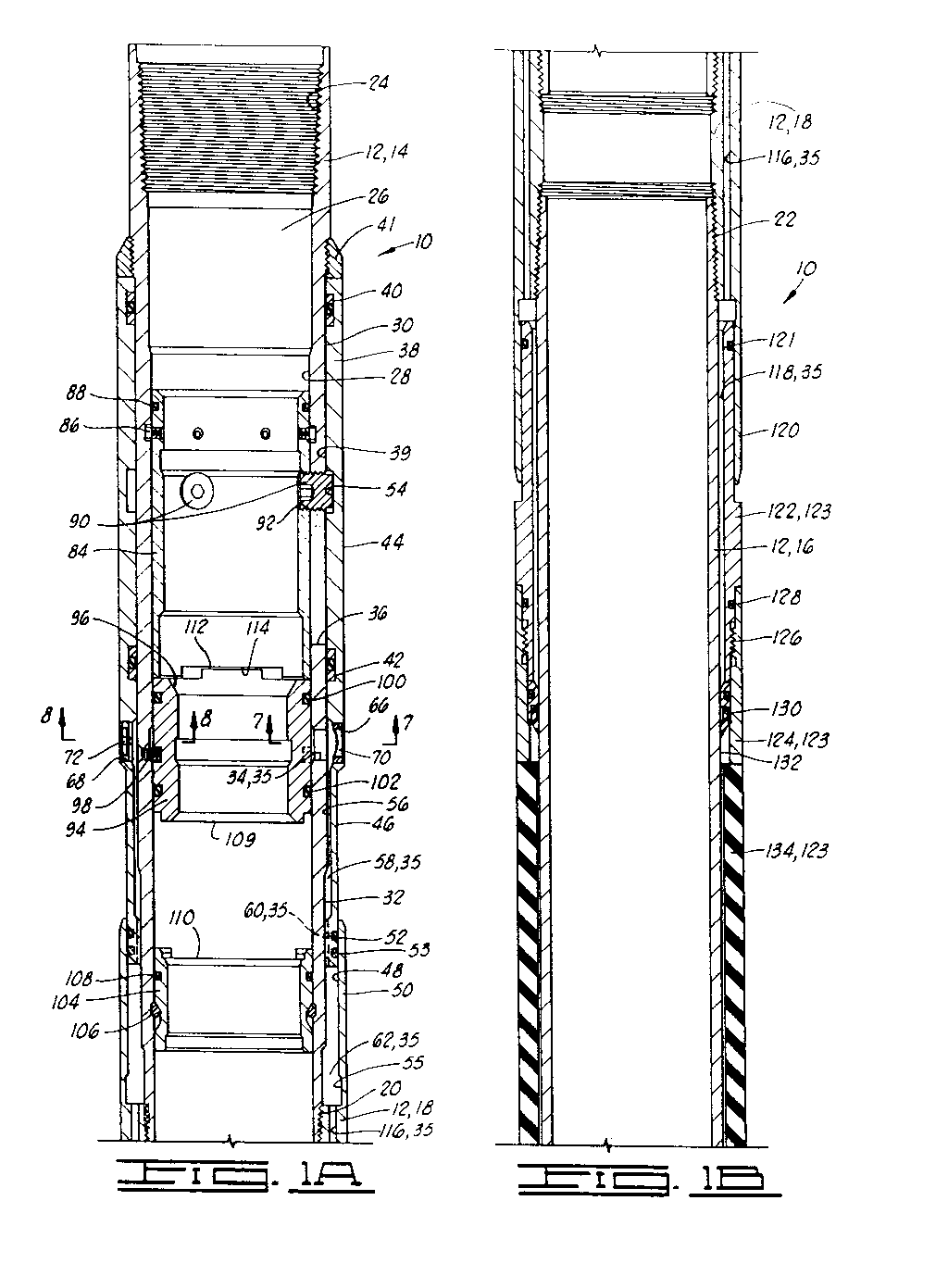
- First embodiment 10 includes a substantially tubular mandrel 12, which may also be referred to as a housing 12, comprising an upper mandrel 14 and a lower mandrel 16.
- Mandrel 12 also comprises a connecting means for interconnecting upper mandrel 14 and lower mandrel 16.
- this connecting means is characterized by a mandrel coupling 18 attached to upper mandrel 14 by threaded connection 20 and to lower mandrel 16 by threaded connection 22.
- Upper mandrel 14 has an internally threaded surface 24 at the upper end thereof adapted for connection to a casing string.
- Mandrel 12 defines an inner passage 26 therein, at least partially defined by bore 28 in upper mandrel 14.
- Upper mandrel 14 of mandrel 12 has a first outer surface 30 and a slightly smaller second outer surface 32 below the first outer surface. At least one transversely disposed mandrel port 34 is defined through the wall of upper mandrel 14 and extends between bore 28 and first outer surface 30. As will be further described herein, mandrel port 34 is used as an inflation port forming part of an inflation passage means 35 and as a cementing port. As will be further described herein, inflation passageway means 35 provides communication between the inner passage 26 in mandrel 12 and inflatable packing means 123 connected to the mandrel.
- slots 36 are also defined in upper mandrel 14. Slots 36 are preferably disposed above mandrel port 34.
- First embodiment 10 includes an outer, external closure sleeve 38 having a bore 39 which is concentrically, closely, slidably received about first outer surface 30 of upper mandrel 14 of mandrel 12.
- Closure sleeve 38 is movable relative to mandrel 12 between an open position, as seen in FIG. 1A, and a closed position wherein mandrel port 34 is covered and closed by closure sleeve 38, as will be further described herein.
- a support ring 41 is threadingly engaged with mandrel 12 above closure sleeve 38 and acts as an upper stop for the closure sleeve.
- a sealing means such as an upper seal 40 and a lower seal 42, provides sealing engagement between closure sleeve 38 and outer surface 30 of upper mandrel 14.
- Upper seal 40 is always disposed above slots 36.
- lower seal 42 is disposed between slots 36 and mandrel port 34.
- Closure sleeve 38 has a first outer surface 44 and a smaller second outer surface 46 below the first outer surface. At least a portion of second outer surface 46 is slidably received within first bore 48 defined in an upper portion 50 of mandrel coupling 18. Thus, upper portion 50 of mandrel coupling 18 acts as a housing for slidably receiving the lower end of closure sleeve 38.
- a sealing means such as an O-ring 52, provides sealing engagement between closure sleeve 38 and upper portion 50 of mandrel coupling 18.
- a lock ring 53 is carried by the lower end of closure sleeve 38 below O-ring 52. Lock ring 53 is adapted for lockingly engaging an undercut 55 at the lower end of first bore 48 so that, when closure sleeve 38 is moved to its closed position, lock ring 53 will lock the closure sleeve in this position.
- a groove 54 and annular recess 56 are defined in closure sleeve 38. Recess 56 generally faces a portion of both first outside diameter 30 and second outside diameter 32 of upper mandrel 14. An annulus 58 is thus defined between closure sleeve 38 and upper mandrel 14 and is in communication with mandrel port 34. Annulus 58 forms a portion of inflation passage means 35.
- a plurality of longitudinal slots 60 insure communication between annulus 58 and another annulus 62 which is defined between upper mandrel 14 and upper portion 50 of mandrel coupling 18. Longitudinal slot 60 and annulus 62 also form portions of inflation passage means 35.
- Closure sleeve 38 also defines a transversely disposed first threaded sleeve port 66 and a second threaded sleeve port 68.
- First threaded sleeve port 66 is preferably aligned with mandrel port 34, and as will be further described herein acts as a pressure relief and cementing port.
- First and second sleeve ports 66 and 68 will be seen to be in communication with annulus 58.
- a pressure relief means 70 is threadingly engaged with first sleeve port 66, and a pressure equalizing means 72 is threadingly engaged with second sleeve port 68.
- pressure relief means 70 is illustrated as a rupture means characterized by a rupture disc 74 which is attached to a rupture disc retainer 76 by means such as braising or welding. Rupture disc retainer 76 is threaded into first sleeve port 66.
- pressure equalizing means 72 is characterized by a back check valve assembly 72.
- Back check valve assembly 72 includes a valve seat 78 which has a plurality of openings 80 therethrough and is threadingly engaged with second sleeve port 68.
- a flexible valve member 82 is attached to the inside of valve seat 78 by a fastening means, such as screw 84. It will be seen by those skit- led in the art that due to the flexibility of valve member 82, fluid may flow inwardly through valve equalizing means 72 but outward flow is prevented. This prevents an undesired pressure differential across rupture disc 74 in pressure relief means 70 as the tool is run into the well bore. That is, pressure equalizing means 72 insures that the pressure on both sides of rupture disc 74 is equalized and rupture disc 74 will not be ruptured inwardly by pressure from the well bore.
- first embodiment 10 includes an inner operating sleeve 84 which is slidably received in bore 28 of upper mandrel 14 of mandrel 12.
- Operating sleeve 84 is slidable between a first position relative to mandrel 12, as seen in FIG. 1A, and a second position corresponding to the closed position of closure sleeve 38, as will be further described herein.
- a plurality of shear pins 86 initially hold operating sleeve 84 in its first position.
- a sealing means such as O-ring 88, provides sealing engagement between operating sleeve 84 and upper mandrel 14.
- a plurality of pins such as the two pins 90 shown in FIG. 1A, extend through slots 36 in upper mandrel 14 and are fixably connected to operating sleeve 84 and closure sleeve 38 for common longitudinal movement relative to mandrel 12 throughout the entire movement of operating sleeve 84 from its first position to its second position. Since pins 90 fixedly connect operating sleeve 84 to closure sleeve 38, there is no lost longitudinal motion of operating sleeve 84 relative to closure sleeve 38 as the operating sleeve moves downwardly to close mandrel port 34 with closure sleeve 38.
- Each pin 90 is threadingly engaged with a threaded opening 92 in operating sleeve 84 and extend through slot 36 in upper mandrel 14 to tightly engage groove 54 in closure sleeve 38.
- Pins 90 in their engagement with operating sleeve 84 and closure sleeve 38 may all be referred to as an interlocking means, and more particularly a mechanical interlocking means, extending through slots 36 and operably associated with both the operating sleeve and the closure sleeve for transferring a closing force from the operating sleeve to the closure sleeve, and thereby moving closure sleeve 38 to its closed position as operating sleeve 84 moves from its first position to its second position.
- Pins 90 also serve to hold operating sleeve 84 so that it will not rotate as operating sleeve 84 is laterdril- led out of mandrel 12 after the cementing job is completed.
- First embodiment 10 further includes an internal lower opening sleeve 94 slidably received in bore 28 of upper mandrel 14 below operating sleeve 84. Opening sleeve 94 is slidable between a closed position as shown in FIG. 1A covering mandrel port 34 and an open position wherein mandrel port 34 is uncovered by opening sleeve 94 as the opening sleeve moves downwardly relative to mandrel 12. It is noted that when opening sleeve 94 is in its closed position as shown in FIG.
- operating sleeve 84 is simultaneously in its first position, and inner passage 26 of upper mandrel 14 of mandrel 12 is in fluid pressure communication with bore 39 of closure sleeve 38 between seals 40 and 42. This is because there is no seal between the lower end of opening sleeve 84 and upper mandrel 14.
- Opening sleeve 94 in the embodiment of FIG. 1A is a plug operated sleeve having an annular seat 96 defined on its upper end which is constructed for engagement with a pump-down or free-fall plug (not shown) of a kind known in the art.
- a plurality of shear pins 98 initially hold opening sleeve 94 in its closed position.
- Asealing means such as upper and lower O-rings 100 and 102, provides sealing engagement between opening sleeve 94 and bore 28 of upper mandrel 14 above and below mandrel port 34, respectively, when the opening sleeve is in its closed position.
- An anchor ring 104 is disposed in bore 28 of upper mandrel 14 and is spaced below opening sleeve 94 when the opening sleeve is in its closed position. Anchor ring 104 is locked in position by a retainer ring 106.
- a sealing means such as O-ring 108, provides sealing engagement between anchor ring 104 and upper mandrel 14.
- opening sleeve 94 When opening sleeve 94 is moved to its open position, as further described herein, it moves downwardly until it abuts anchor ring 104. A lower end 109 of opening sleeve 94 acts as a lug which is received within an upwardly facing recess 110 on anchor ring 104 when the opening sleeve is moved to its closed position. This prevents opening sleeve 94 from rotating relative to anchor ring 104 in mandrel 12 at a later time when the internal components are drilled out of mandrel 12.
- a lug 112 on the upper end of opening sleeve 94 is received within a downwardly facing recess 114 on the lower end of operating sleeve 84 when the opening sleeve is in its open position and the operating sleeve is moved to its second position. This prevents operating sleeve 84 from rotating relative to opening sleeve 94 in mandrel 12 at a later time when the internal components are drilled out of the mandrel.
- At least one longitudinally disposed passageway 116 is disposed through mandrel coupling 18 and provides communication between annulus 62 and a lower annulus118. Passageway 116 and lower annulus 118 form portions of inflation passage means 35.
- a lower portion 120 of mandrel coupling 18 has the upper end of a check valve retainer 122 disposed therein, and it will be seen that at least a portion of annulus 118 is defined between check valve retainer 122 and lower mandrel 16 of mandrel 12.
- a sealing means, such as O-ring 121 provides sealing engagement between check valve retainer 122 and lower portion 120 of mandrel coupling 18.
- Check valve retainer 122 is a portion of an inflatable packing means 123 which is connected to mandrel 12. More particularly, inflatable packing means 123 is substantially disposed about lower mandrel 16. Inflatable packing means 123 also includes an upper packer shoe 124 which is attached to check valve retainer 122 at threaded connection 126. A sealing means, such as O-ring 128, provides sealing engagement therebetween.
- a check valve 130 is disposed adjacent to the lower end of check valve retainer 122 and sealingly engages outer surface 132 of lower mandrel 16.
- Check valve 130 is of a kind known in the art and allows fluid flow downwardly while preventing upward fluid flow.
- Inflatable packing means 123 also comprises an elastomeric packer element 134 which is disposed around lower mandrel 16 and attached to upper packer shoe 124.
- inflatable packing means 123 further includes a lower packer shoe 136 which is connected to the lower end of packer element 134.
- the lower end of lower mandrel 16 of mandrel 12 is connected to lower packer shoe 136 at threaded connection 138.
- lower packer shoe 136 is fixedly attached to lower mandrel 16, such as by welding.
- lower packer shoe 136 is integral with lower mandrel 16 and may be considered a portion thereof.
- a lower nipple 140 is connected to lower packer shoe 136 at threaded connection 142.
- the lower end of lower nipple 140 is adapted for connection to lower casing string components.
- Second embodiment 150 is virtually the same as first embodiment 10 except for the opening sleeve.
- Second embodiment 150 includes a hydraulically operated opening sleeve 152 which has a reduced diameter lower portion 154 which is slidably received within a bore 156 of anchor ring 104.
- An upper sliding sealing means such as O-ring 158, provides sealing engagement between opening sleeve 152 and bore 28 in upper mandrel 14 of mandrel 12, and a lower sliding sealing means, such as O-ring 160, provides sealing engagement between operating sleeve 152 and bore 156 in anchor ring 104.
- opening sleeve 152 when opening sleeve 152 is in its initial, closed position, it covers and sealingly closes mandrel port 34 in upper mandrel 14 due to the action of seals 158 and 160 and O-ring 108 which seals between anchor ring 104 and bore 28 in upper mandrel 14.
- Opening sleeve 152 is initially held in this closed position by a plurality of shear pins 162.
- a high predetermined pressure can be applied to inner passage 26 through mandrel 12, and this pressure will act downwardly on the differential area between O-rings 158 and 160 until the force exceeds that which can be held by shear pins 162. Shear pins 162 will then shear, and the downwardly acting differential pressure will move opening sleeve 152 downwardly until a shoulder 164 thereon engages anchor ring 104.
- opening sleeve 152 may be opened using a pump-down or free-fall plug to move the opening sleeve to its open position in a manner substantially identical to opening sleeve 94 in first embodiment 10.
- Opening sleeve 152 has an upwardly extending lug 166 which will be received by downwardly facing recess 114 in operating sleeve 84 when opening sleeve 152 is in its open position and operating sleeve 84 is moved to its second position.
- Non-rotating engagement is provided between shoulder 164 of opening sleeve 152 and the upper end of anchor ring 104 by a similar lug and recess type interlocking structure (not shown). This interlocking prevents operating sleeve 84 from rotating relative to opening sleeve 152 and prevents opening sleeve 152 from rotating relative to anchor ring 104 and mandrel 12 at a later time when the internal components are drilled out of mandrel 12.
- Either first embodiment 10 or second embodiment 150 of the stage cementer and inflation packer is made up as part of the casing string which is run into the well bore in a manner known in the art.
- the apparatus is in the configuration shown in FIGS. 1A-1CorF)GS. 2A-2C when run into the well bore.
- Cementing of the first or bottom stage below apparatus 10 or 150 is carried out in a manner known in the art. This places cement between the casing and the well bore at a location below apparatus 10 or 150.
- the opening sleeve is actuated. In the first embodiment of FIGS. 1A-1C, this is accomplished by dropping into the casing a pump-down or free-fall opening plug (not shown) of a kind known in the art.
- the opening plug engages annular seat 96 in opening sleeve 94.
- a pump-down or free-fall plug is not required. Rather, pressure is increased within the casing string and thus within the second embodiment apparatus 150 which acts against the differential area defined on opening sleeve 152 between O-rings 158 and 160 until shear pins 162 are sheared and opening sleeve 152 is moved downwardly until shoulder 164 thereof contacts anchor ring 104. This places opening sleeve 152 in its open position, and it will be seen by those skilled in the art, that, as with first embodiment 10, mandrel port 34 is thus opened and placed in communication with inner passage 26 of mandrel 12. As previously mentioned, a plug may be used to open opening sleeve 152 if the pressure is not sufficiently high.
- first embodiment 10 and second embodiment 150 are identical.
- fluid passes through inflation passage means 35 to inflatable packing means 123. That is, fluid passes from inner passage 26 through mandrel port 34 into annulus 58, then through longitudinal passageway 116 and lower annulus 118 to check valve 130. The fluid flows past check valve 130 into inflatable packing means 123. Check valve 130 insures that there is no back flow out of inflatable packing means 123. As packer element 134 inflates, check valve retainer 122 which is attached to upper packer shoe 124 slides downwardly within lower portion 120 of mandrel coupling 18, allowing packer element 134 to be brought into sealing engagement with the well bore.
- rupture disc 74 of pressure relief means 70 will rupture outwardly. It will be seen that this places first sleeve port 66 in closure sleeve 38 and mandrel port 34 in communication with the well annulus. Then cement for the second stage cementing can be pumped down the casing with the displacing fluids located therebelow being circulated through aligned ports 34 and 66 and back up the well annulus. A bottom cementing plug (not shown) may be run below the cement, and a top cementing plug (not shown) is run at the upper extremity of the cement, in a manner known in the art.
- the bottom plug if any, will seat against operating sleeve 84, and further pressure applied to the cement column will rupture a rupture disc in the bottom cementing plug. The cement will then flow through the bottom cementing plug and through aligned ports 34 and 66 and upwardly through the well annulus.
- Second outer surface 46 on closure sleeve 38 slides downwardly within upper portion 50 of mandrel coupling 18. Downward movement of operating sleeve 84 and closure sleeve 38 stops when the lower end of operating sleeve 84 engages the top of opening sleeve 94 in first embodiment 10 or opening sleeve 152 in second embodiment 150.
- the upper and lower cementing plugs, operating sleeve 84, opening sleeve 94 or 152, and anchor ring 104 can all be drilled out of mandrel 12 leaving a smooth bore through the apparatus.
- the components to be drilled out may be made of easily drillable material such as aluminum. Since all of the components are non-rotatably locked to each other and to mandrel 12, as previously described, the drilling out of the components is further aided.
- Third embodiment 180 includes a substantially tubular mandrel 182, which may also be referred to as a housing 182.
- Mandrel 182 has an internally threaded surface 184 at the upper end thereof adapted for connection to a casing string. Mandrel 182 defines an inner passage 186 therein, at least partially defined by first bore 188 in the mandrel. Below first bore 188 is a second bore 189 forming a recess in mandrel 182.
- Mandrel 182 has a first outer surface 190 and a slightly smaller second outer surface 192 below the first outer surface.
- Mandrel 182 defines a transversely disposed first threaded mandrel port 194 and a second threaded mandrel port 196.
- first threaded mandrel port 194 acts as a cementing port 194.
- First and second mandrel ports 194 and 196 extend between first bore 188 and first outer surface 190 of mandrel 182.
- a pressure relief means 70 is threadingly engaged with first mandrel port 194, and a pressure equalizing means 72 is threadingly engaged with second mandrel port 196.
- Pressure relief means 70 and pressure equalizing means 72 are the same as in first embodiment 10 and second embodiment 150 of the apparatus. Referring again to FIGS. 7 and 8, details of pressure relief means 70 and pressure equalizing means 72 are shown, as previously described.
- Mandrel 182 also defines an annular recess 197 and at least one transversely disposed third mandrel port 198 through a wall thereof which extends between second bore 189 and second outer surface 192.
- Third mandrel port 198 is used as an inflation port and is in communication with recess 197.
- Recess 197 and third mandrel port 198 form parts of an inflation passage means 199 for providing communication between inner passage 186 and an inflatable packing means 251 as further described herein.
- slots 200 are also defined in mandrel 182. Slots 200 are preferably disposed above first and second mandrel ports 194 and 196.
- Third embodiment 180 includes an outer, external closure sleeve 202 having a bore 205 which is concentrically, closely, slidably received about first outer surface 190 of mandrel 182.
- Closure sleeve 202 is movable relative to mandrel 182 between an open position, as seen in FIG. 3A, in which the closure sleeve is disposed above first and second mandrel ports 194 and 196, and a closed position wherein mandrel ports 194 and 196 are covered and closed by closure sleeve 202, as will be further described herein.
- a support ring 204 is threadingly engaged with mandrel 182 above closure sleeve 202 and acts as an upper stop for the closure sleeve.
- Asealing means such as upper seal 206 and lower seal 208, provides sealing engagement between closure sleeve 202 and outer surface 190 of mandrel 182.
- Upper seal 206 is always disposed above slots 200.
- lower seal 208 is disposed between slots 200 and first and second mandrel ports 194 and 196.
- Closure sleeve 202 also defines a groove 209 therein which is located between upper seal 206 and lower seal 208.
- a retainer ring 210 is carried by the lower end of closure sleeve 202 below lower seal 208.
- Retainer ring 210 is adapted for locking engagement with a retainer ring groove 212 defined in outer surface 190 of mandrel 182 at a position below first and second mandrel ports 194 and 196.
- Third embodiment 180 includes an inner operating sleeve 214 which is slidably received in bore 188 of mandrel 182.
- Operating sleeve 214 may be substantially identical to operating sleeve 84 in first embodiment 10 and second embodiment 150 and is slidable between a first position relative to mandrel 182, as seen in FIG. 3A, and a second position corresponding to the closed position of closure sleeve 202, as will be further described herein.
- a plurality of shear pins 216 initially hold operating sleeve 214 in its first position.
- a sealing means such as O-ring 218, provides sealing engagement between operating sleeve 214 and mandrel 182.
- a plurality of pins extend through slots 200 in mandrel 182 and are fixably connected to operating sleeve 214 and closure sleeve 202 for common longitudinal movement relative to mandrel 182 throughout the entire movement of operating sleeve 214 from its first position to its closed position. Since pins 220 fixedly connect operating sleeve 214 with closure sleeve 202, there is no lost longitudinal motion of operating sleeve 214 relative to closure sleeve 202 as the operating sleeve moves downwardly to close mandrel ports 194 and 196 with closure sleeve 202.
- Each pin 220 may be substantially identical to pin 90 in first embodiment 10 and second embodiment 150 and is threadingly engaged with a threaded opening 222 in operating sleeve 214 and extend through slot 200 in mandrel 182 to tightly engage groove 209 in closure sleeve 202.
- Pins 220 in their engagement with operating sleeve 214 and closure sleeve 202 may all be referred to as an interlocking means, and more particularly a mechanical interlocking means, extending through slots 200 and are operably associated with both the operating sleeve and the closure sleeve for transferring a closing force from the operating sleeve to the closure sleeve and thereby moving closure sleeve 202 to its closed position as operating sleeve 214 moves from its first position to its second position.
- Pins 220 also serve to hold operating sleeve 214 so that it will not rotate as operating sleeve 214 is later drilled out of mandrel 182 after the cementing job is completed.
- Third embodiment 180 further includes an internal lower opening sleeve 224 slidably received in bore 188 of mandrel 182 below operating sleeve 214. Opening sleeve 224 is slidable between a closed position as shown in FIG. 3A covering mandrel ports 194 and 196 and an open position wherein mandrel ports 194 and 196 are uncovered by opening sleeve 224 as the opening sleeve moves downwardly relative to mandrel 182. It is noted thatwhen opening sleeve 224 is in its closed position as shown in FIG.
- operating sleeve 214 is simultaneously in its first position, and inner passage 186 of mandrel 182 is in fluid pressure communication with bore 205 of closure sleeve 202 between seals 206 and 208. This is because there is no seal between the lower end of opening sleeve 214 and mandrel 182.
- Opening sleeve 224 in the embodiment of FIG. 3A is a plug-operated sleeve having an annular seat 226 on its upper end which is constructed for engagement with a pump-down or free-fall plug (not shown) of a kind known in the art.
- a plurality of shear pins 228 initially hold opening sleeve 224 in its closed position.
- Opening sleeve 224 has a first outer surface 230 which is concentrically, closely, slidably received within bore 188 in mandrel 182.
- Operating sleeve 224 also has a smaller second outer surface 232 below first outer surface 230, and a chamfered shoulder 234 extends between first outer surface 230 and second outer surface 232.
- a plurality of longitudinal slots 236 are formed in first outer surface 230 of operating sleeve 224. Slots 236 form a part of inflation passage means 199 and are in communication with recess 197 in mandrel 182. Slots 236 extend downwardly through shoulder 234 so that slots 236 are also in communication with an annulus 238 defined between second bore 189 in mandrel 182 and operating sleeve 224. Annulus 238 also forms a part of inflation passage means 199.
- first and second mandrel ports 194 and 196 are in communication with each other and further in communication with third mandrel ports 198.
- a sealing means such as upper and lower O-rings 240 and 242, provide sealing engagement between opening sleeve 224 and mandrel 182, above first and second mandrel ports 194 and 196 and below third mandrel ports 198, respectively, when the opening sleeve is in its closed position.
- a retainer ring 244 is engaged with a retainer ring groove 246 in mandrel 182.
- Second outer surface 232 of operating mandrel 214 is sized such that it will slide within retainer ring 244 as the operating sleeve is moved downwardly.
- operating sleeve 224 When operating sleeve 224 is moved to its open position, as further described herein, it moves downwardly until shoulder 234 thereon abuts retainer ring 244, locking the operating sleeve with respect to mandrel 182. This locking action prevents operating sleeve 224 from rotating relative to mandrel 182 at' a later time when the internal components are drilled out of the mandrel.
- a lug 248 on the upper end of opening sleeve 224 is received within a downwardly facing recess 250 on the lower end of operating sleeve 214 when the opening sleeve is in its open position and the operating sleeve is moved to its second position. This prevents operating sleeve 214 from moving relative to opening sleeve 224 and mandrel 182 at a later time when the internal components are drilled out of the mandrel.
- inflatable packing means 251 is disposed about mandrel 182 below retainer ring groove 212. At its upper end, inflatable packing means 251 includes a check valve retainer 252 which is disposed around second outer surface 190 of mandrel 182. Check valve retainer 252 is dimensioned such that an annulus 254 is defined therebetween. It will be seen that annulus 254 is in communication with third mandrel port 198.
- a check valve 256 is disposed adjacent to the lower end of check valve retainer 252 and sealingly engages third outer surface 258 of mandrel 182.
- Check valve 256 is of a kind known in the art and allows fluid flow downwardly while preventing upward fluid flow.
- a sealing means such as O-ring 260, provides sealing engagement between check valve retainer 252 and mandrel 182 above third mandrel port 198.
- Inflatable packing means 251 includes an upper packer shoe 262 is disposed around check valve retainer 252 and is connected thereto at threaded connection 264.
- a sealing means such as an upper O-ring 266, shown in FIG. 3A, and a lower O-ring 268, shown in FIG. 3B, provide sealing engagement between upper packer shoe 262 and check valve retainer 252.
- Inflatable packing means 251 also includes an elastomeric packer element 270 which is disposed around the lower portion of mandrel 182 and attached to upper packer shoe 262. Packer element 270 may be substantially identical to first and second embodiment packer element 134.
- lower end of packer element 270 is connected to a lower packer shoe 272.
- Lower packer shoe 272 also forms a part of inflatable packing means 251.
- the lower end of mandrel 182 is connected to lower packer shoe 272 at threaded connection 274.
- a lower nipple 276 is connected to lower packer shoe 272 at threaded connection 278.
- the lower end of lower nipple 276 is adapted for connection to lower casing string components.
- Lower packer shoe 272 and lower nipple 276 may be substantially identical to those components in the first and second embodiments.
- a fourth embodiment of the stage cementer and inflation packer apparatus of the present invention is shown and generally designated by the numeral 290.
- Fourth embodiment 290 is virtually the same as third embodiment 180 except for the opening sleeve and the addition of an anchor ring 302.
- Fourth embodiment 290 includes a hydraulically operated opening sleeve 292 with a first outer surface 294 and a reduced diameter outer surface 296.
- an annulus 297 is defined between operating sleeve 292 and mandrel 182.
- a plurality of slots 298 are defined in first outer surface 294 and are in communication with annulus 297 and with first and second mandrel ports 194 and 196. Slots 298 generally face recess 197 in mandrel 182. Slots 298, recess 197, annulus 297, third mandrel port 198 and annulus 254 form parts of an inflation passage means 299.
- Second outer surface 296 of operating sleeve 292 is slidably received within bore 300 of anchor ring 302.
- Anchor ring 302 is disposed in mandrel 182 and is locked in position by retainer ring 304, as seen in FIG. 4B.
- a sealing means, such as O-ring 306, provides sealing engagement between anchor ring 302 and mandrel 182.
- An upper sliding sealing means such as O-ring 308 provides sealing engagement between opening sleeve 292 and mandrel 182
- a lower sealing means such as O-ring 310, provides sealing engagement between operating sleeve 292 and bore 300 in anchor ring 302. It will be seen by those skilled in the art that when opening sleeve 292 is in its initial, closed position, it covers and sealingly closes first and second mandrel ports 194 and 196 in mandrel 182 due to the action of O-rings 308 and 310.
- Opening sleeve 292 is initially held in this closed position by a plurality of shear pins 312.
- a high pressure can be applied to inner passage 186 through mandrel 182, and this pressure will act downwardly on the differential area between O-rings 308 and 310 until a force exceeds that which can be held by shear pins 312. Shear pins 312 will then shear, and the downwardly acting differential pressure will move opening sleeve 292 downwardly until a shoulder 314 thereon engages anchor ring 302.
- opening sleeve 292 may be opened using a pump-down or free-fall plug to move the opening sleeve to its open position in a manner substantially identical to opening sleeve 224 in third embodiment 180.
- Opening sleeve 292 has an upwardly extending lug 316 which will be received by downwardly facing recess 250 in operating sleeve 214 when opening sleeve 292 is in its open position and operating sleeve 214 is moved to its second position.
- Non-rotating engagement is provided between shoulder 314 of opening sleeve 292 and the upper end of anchor ring 302 by a similar lug and recess type interlocking structure (not shown). This interlocking prevents operating sleeve 214 from rotating relative to opening sleeve 292 and prevents opening sleeve 292 from rotating relative to anchor ring 302 and mandrel 182 at a later time when the internal components are drilled out of mandrel 182.
- Either third embodiment 180 or fourth embodiment 290 of the stage cementer and inflation packer is made up as part of the casing string which is run into the well bore in a manner known in the art.
- the apparatus is in the configuration shown in FIGS. 3Aand 3B or FIGS. 4A and 4B when run into the well bore.
- Cementing of the first or bottom stage below apparatus 180 or 290 is carried out in a manner known in the art. This places cement between the casing and the well bore at a location below apparatus 180 or 290.
- opening sleeve is actuated.
- this is accomplished by dropping into the casing a pump-down or free-fall opening plug (not shown) of a kind known in the art. Opening plug engages annular seat 226 in opening sleeve 224.
- first and second mandrel ports 194 and 196 are thus placed in communication with inner passage 186 in mandrel 182.
- fluid passes from inner passage 186 around the upper end of operating sleeve 224, through recess 197, slots 236, annulus 238 and annulus 297 and then through third mandrel ports 298 into annulus 254.
- fluid is communicated from inner passage 186 to packerele- ment 270 through inflation passage means 199 of third embodiment 180.
- the fluid flows past check valve 256 into the packer portion.
- a pump-down or free-fall plug is not required. Rather, pressure is increased within the casing string and thus within the fourth embodiment apparatus 290 which acts against the differential area defined on opening sleeve 292 between 0-rings 308 and 310 until shear pins 312 are sheared and opening sleeve 292 is moved downwardly until shoulder 314 thereof contacts anchor ring 302. This places opening sleeve 292 in its open position, and it will be seen by those skilled in the art, that, as with third embodiment 180, first and second mandrel ports 194 and 196 are thus placed in communication with inner passage 186 of mandrel 182. As previously mentioned, a plug may be used to open opening sleeve 292 if the pressure is not sufficiently high.
- fluid passes from inner passage 186 around the upper end of opening sleeve 294, through recess 197, slots 298 and annulus 297 and then through third mandrel port 198 into annulus 254.
- fluid passes from inner passage 186 to packer element 270 through inflation passage means 299 in fourth embodiment 290.
- the fluid flows past check valve 256 into the packer portion.
- third embodiment 180 and fourth embodiment 290 are identical.
- Check valve 256 insures that there is no back flow out of the packer portion. As packer element 270 inflates, check valve retainer 252 and upper packer shoe 262 attached thereto slide downwardly along second outer surface 192 of mandrel 182, allowing packer element 270 to be brought into sealing engagement with the well bore.
- rupture disc 74 of pressure relief means 70 will rupture outwardly. It will be seen that this places inner passage 186 in communication with the well annulus. Then cement for the second stage cementing can be pumped down the casing with the displacing fluids located therebelow being circulated through opened first mandrel port 194 and back up the well annulus. A bottom cementing plug (not shown) may be run below the cement, and a top cementing plug (not shown) is run at the upper extremity of the cement, in a manner known in the art.
- the bottom plug if any, will seat against operating sleeve 214, and further pressure applied to the cement column will rupture a rupture disc in the bottom cementing plug. The cement will then flow through the bottom cementing plug and through first mandrel port 194 and upwardly through the well annulus.
- closure sleeve 202 is moved downwardly from its open to closed position as operating sleeve 214 is moved downwardly from its first to its second position.
- lower seal 208 in closure sleeve 202 is moved below first and second mandrel ports 194 and 196, thus sealingly separating first and second mandrel ports 194 and 196 from the well annulus.
- the upper and lower cementing plugs, operating sleeve 214, opening sleeve 224 or 294, and anchor ring 302 can all be drilled out of mandrel 182 leaving a smooth bore through the apparatus.
- the components to be drilled out may be made of easily drillable material such as aluminum. Since all of the components are non-rotatably locked to each other and to mandrel 186, as previously described, the drilling out of the components is further aided.
- a fifth embodiment of the stage cementer and inflation packer apparatus of the present invention is shown and generally designated by the numeral 330.
- Fifth embodiment 330 includes a substantially tubular mandrel 332, which may also be referred to as a housing 332.
- Mandrel 332 has an internally threaded surface 334 at the upper end thereof adapted for connection to a casing string. Mandrel 332 defines an inner passage 336 therein, at least partially defined by bore 338.
- Mandrel 332 has a first outer surface 340 and a slightly smaller second outer surface 342 below the first outer surface. At least one transversely disposed mandrel port 344 is defined through the wall of mandrel 332 and extends between bore 338 and first outer surface 340. As will be further described herein, mandrel port 344 is used as an inflation port and as a cementing port.
- slots 346 are also defined in mandrel 332. Slots 346 are preferably disposed above mandrel port 344.
- Fifth embodiment 330 includes an outer, external closure sleeve 348 having a bore 350 therethrough which is concentrically, closely, slidably received about first outer surface 340 of mandrel 332.
- Closure sleeve 348 is movable relative to mandrel 332 between an open position, as seen in FIG. 5A, and a closed position wherein mandrel port 344 is covered and closed by closure sleeve 348, as will be further described herein.
- a support ring 352 is threadingly engaged with mandrel 332 above closure sleeve 348.
- Support ring 352 provides an upper limit of movement for closure sleeve 348.
- a sealing means such as an upper seal 356 and a lower seal 358, provide sealing engagement between closure sleeve 348 and outer surface 340 of mandrel 332.
- Upper seal 356 is always disposed above slots 346.
- lower seal 358 is disposed between slots 346 and mandrel port 344.
- a retainer ring 360 is carried by closure sleeve 348 below lower seal 358.
- Retainer ring 360 is adapted for locking engagement with retainer ring groove 362 defined in first outer surface 340 of mandrel 332 to limit downward movement of closure sleeve 348 as it is moved from the open position shown in FIG. 5A to its closed position.
- Closure sleeve 348 further defines a groove 364 therein which is positioned between upper seal 356 and lower seal 358.
- Closure sleeve 348 has an outer surface 366 which is slidably received within a bore 368 defined within a check valve retainer 370.
- check valve retainer 370 acts as a housing for slidably receiving at least the lower portion of closure sleeve 348.
- Check valve retainer 370 also forms an upper part of an inflatable packing means 371 disposed around mandrel 332.
- a sealing means such as O-ring 372, provides sealing engagement between closure sleeve 348 and check valve retainer 370.
- annulus 374 is defined between check valve retainer 370 and mandrel 332 below closure sleeve 348. Mandrel port 344 and annulus 374 form an inflation passage means 375, as further described herein.
- Check valve retainer 370 defines a transversely disposed first threaded body or housing port 376 and a second threaded body or housing port 378.
- First and second body ports 376 and 378 will be seen to be in communication with annulus 374.
- first and second body ports 376 and 378 are disposed longitudinally below mandrel port 344.
- First body port 376 acts as a cementing port, as will be further described herein.
- a pressure relief means 70 is threadingly engaged with first body port 376, and a pressure equalizing means 72 is threadingly engaged with second body port 378.
- pressure relief means 70 and pressure equalizing means 72 are respectively shown and are the same as described for first embodiment 10.
- third embodiment 330 includes an inner operating sleeve 380 which is slidably received in bore 338 of mandrel 332.
- Operating sleeve 380 is slidable between a first position relative to mandrel 332, as seen in FIG. 5A, and a second position corresponding to the closed position of closure sleeve 348, as will be further described herein.
- Operating sleeve 380 may be substantially identical to the operating sleeves described above for the other embodiments.
- a plurality of shear pins 382 initially hold operating sleeve 380 in its first position.
- a sealing means such as O-ring 384, provides sealing engagement between operating sleeve 380 and mandrel 332.
- a plurality of pins such as the two pins 386 shown in FIG. 5A, extend through slots 346 in mandrel 332 and are fixably connected to operating sleeve 380 and closure sleeve 348 for common longitudinal movement relative to mandrel 332 throughout the entire movement of operating sleeve 380 from its first position to its second position. Since pins 386 fixedly connect operating sleeve 380 to closure sleeve 348, there is no lost longitudinal motion of operating sleeve 380 relative to closure sleeve 348 as the operating sleeve moves downwardly to close mandrel port 344 with closure sleeve 348.
- Each pin 386 is threadingly engaged with a threaded opening 388 in operating sleeve 380 and extend through slot 346 in mandrel 332 to tightly engage groove 364 in closure sleeve 348.
- Pins 386 in their engagement with operating sleeve 380 and closure sleeve 348 may all be referred to as an interlocking means, and more particularly a mechanical interlocking means, extending through slots 346 and are operably associated with both the operating sleeve and the closure sleeve for transferring a closing force from the operating sleeve to the closure sleeve and thereby moving closure sleeve 348 to its closed position as operating sleeve 380 moves from its first position to its second position.
- Pins 386 also serve to hold operating sleeve 380 so that it will not rotate as operating sleeve 380 is later drilled out of mandrel 332 after the cementing job is completed.
- Fifth embodiment 330 further includes an internal loweropening sleeve 390 slidably received in bore 338 of mandrel 332 below operating sleeve 380.
- Opening sleeve 390 may be substantially identical to opening sleeve 94 in first embodiment 10 and second embodiment 150, and opening sleeve 390 is slidable between a closed position as shown in FIG. 5A covering mandrel port 344 and an open position wherein mandrel port 344 is uncovered by opening sleeve 390 as the opening sleeve moves downwardly relative to mandrel 332. It is noted thatwhen opening sleeve 390 is in its closed position as shown in FIG.
- operating sleeve 380 is simultaneously in its first position, and inner passage 336 of mandrel 332 is in fluid communication with bore 350 of closure sleeve 348 between seals 356 and 358. This is because there is no seal between the lower end of opening sleeve 380 and mandrel 332.
- Opening sleeve 390 in the embodiment of FIG. 5A-5B is a plug-operated sleeve having an annular seat 392 defined on its upper end which is constructed for engagement with a pump-down orfree-fall plug (not shown) of a kind known in the art.
- a plurality of shear pins 394 initially hold opening sleeve 390 in its closed position.
- a sealing means such as upper and lower O-rings 396 and 398, provides sealing engagement between opening sleeve 390 and bore 338 of mandrel 332 above and below mandrel port 344, respectively, when the opening sleeve is in its closed position.
- An anchor ring 400 is disposed in bore 338 of mandrel 332 and is spaced below opening sleeve 390 when the opening sleeve is in its closed position.
- Anchor ring 400 may be substantially identical to anchor 104 in first embodiment 10 and second embodiment 150.
- Anchor ring 400 is locked in position by a retainer ring 402.
- a sealing means such as O-ring 404, provides sealing engagement between anchor ring 400 and mandrel 332.
- opening sleeve 390 When opening sleeve 390 is moved to its open position, as further described herein, it moves downwardly until it abuts anchor ring 400.
- a lower end 406 of opening sleeve 390 acts as a lug which is received within an upwardly facing recess 408 on anchor ring 400 when the opening sleeve is moved to its closed position. This prevents opening sleeve 390 from rotating relative to anchor ring 400 in mandrel 332 at a later time when the internal components are drilled out of mandrel 332.
- a lug 410 on the upper end of opening sleeve 390 is received within the downwardly facing recess 412 on the lower end of operating sleeve 380 when the opening sleeve is in its open position and the operating sleeve is moved to its second position. This prevents operating sleeve 380 from rotating relative to opening sleeve 390 in mandrel 332 at a later time when the internal components are drilled out of the mandrel.
- Inflatable packing means 371 includes an upper packer shoe 414 which is attached to check valve retainer 370 at threaded connection 416.
- a sealing means such as O-rings 418 and 420, provides sealing engagement therebetween.
- a check valve 422 is disposed adjacent to the lower end of check valve retainer 370 and sealingly engages a third outer surface 424 of mandrel 332.
- Check valve 370 is of a kind known in the art and allows fluid flow downwardly while preventing upward fluid flow.
- Inflatable packing means 371 also includes an elastomeric packer element 426 which is disposed around mandrel 332 and attached to upper packer shoe 414.
- lower end of packer element 426 is connected to a lower packer shoe 428.
- Lower packer shoe 428 is also a portion of inflatable packing means 371.
- the lower end of mandrel 332 is connected to lower packer shoe 428 at threaded connection 430.
- a lower nipple 432 is connected to lower packer shoe 428 at threaded connection 434.
- the lower end of lower nipple 432 is adapted for connection to lower casing string components.
- Packer element 426, lower packer shoe 428 and lower nipple 432 may be substantially identical to the corresponding components described in the other embodiments of the invention.
- FIGS. 6A and 6B a sixth embodiment of the stage cementer and inflation apparatus of the present invention is shown and generally designated by the numeral 450.
- Sixth embodiment 450 is virtually the same as fifth embodiment 330 except for the opening sleeve.
- An anchor ring 452 is disposed in bore 338 of mandrel 332 and is locked in position by a retainer ring 454.
- Anchor ring 452 defines a bore 456 therethrough.
- a sealing means such as O-ring 458, provides sealing engagement between anchor ring 452 and mandrel 332.
- Sixth embodiment 450 includes a hydraulically operated opening sleeve 460 which has a reduced diameter lower portion 462 which is slidably received within bore 456 of anchor ring 452.
- An upper sliding sealing means such as O-ring 464, provides sealing engagement between opening sleeve 460 and bore 338 in mandrel 332, and a lower sealing means, such as O-ring 466, provides sealing engagement between opening sleeve 460 and anchor ring 452.
- opening sleeve 460 when opening sleeve 460 is in its initial, closed position, it covers and sealingly closes mandrel port 344 in mandrel 332 due to the action of seals 464 and 466 and O-ring 458 which seals between anchor ring 452 and bore 338 of mandrel 332.
- Opening sleeve 460 is initially held in this closed position by a plurality of shear pins 468.
- a high pressure can be applied to inner passage 336 through mandrel 332, and this pressure will act downwardly on the differential area between O-rings 464 and 466 until the force exceeds that which can be held by shear pins 468. Shear pins 468 then shear, and the downwardly acting differential pressure will move opening sleeve 460 downwardly until a shoulder470 thereon engages anchor ring 452.
- opening sleeve 460 may be opened using a pump-down or free-fall plug to move the opening sleeve to its open position in a manner substantially identical to opening sleeve 390 in fifth embodiment 330.
- Opening sleeve 460 has an upwardly extending lug 472 which will be received by downwardly facing recess 412 in operating sleeve 380 when opening sleeve 460 is in its open position and operating sleeve 380 is moved to its second position.
- Non-rotating engagement is provided between shoulder 470 of opening sleeve 460 in the upper end of anchor ring 452 by a similar lug and recess type interlocking structure (not shown).
- This interlocking prevents operating sleeve 380 from rotating relative to opening sleeve 460 and prevents opening sleeve 460 from rotating relative to anchor ring 452 in mandrel 332 at a later time when the internal components are drilled out of mandrel 332.
- Eitherfifth embodiment 330 or sixth embodiment 450 of the stage cementer and inflation packer is made up as part of the casing string which is run into the well bore in a manner known in the art.
- the apparatus is in the configuration shown in FIGS. 5Aand 5B or FIGS. 6Aand 6B when run into the well bore.
- Cementing of the first or bottom stage below apparatus 330 or 450 is carried out in a manner known in the art. This places cement below the casing in the well bore at a location below apparatus 330 or 450.
- the opening sleeve is actuated.
- this is accomplished by dropping into the casing a pump-down or free-fall opening plug (not shown) of a kind known in the art.
- the opening plug engages annular seat 392 in opening sleeve 390.
- opening sleeve 390 is then applied to the casing which forces the opening plug against opening sleeve 390, thereby shearing shear pins 394 and moving opening sleeve 390 downwardly from its closed position until lower end 406 thereof contact anchor ring 400.
- a pump-down or free-fall plug is not required. Rather, pressure is increased within the casing string and thus within sixth embodiment apparatus 450 which acts against the differential area defined on opening sleeve 460 between O-rings 464 and 466 until shear pins 468 are sheared and opening sleeve 460 is moved downwardly until shoulder 470 thereof contacts anchor ring 452. This places opening sleeve 460 in its open position, and it will be seen by those skilled in the art, that, as with fifth embodiment 330, mandrel port 344 is thus opened and placed in communication with inner passage 336 of mandrel 332. As previously mentioned, a plug may be used to open opening sleeve 460 if the pressure is not sufficiently high.
- fifth embodiment 330 and sixth embodiment 450 are identical.
- rupture disc 74 of pressure relief means 70 will rupture outwardly. It will be seen that this places retainer port 376 in check valve retainer 370 and mandrel port 344 in communication with the well annulus. Then cement for the second stage cementing can be pumped down the casing with the displacing fluids located therebelow being circulated through mandrel port 344, annulus 374 and body port 376 and back up the well annulus.
- a bottom cementing plug (not shown) may be run below the cement, and a top cementing plug (not shown) is run at the upper extremity of the cement, in a manner known in the art.
- the bottom plug if any, will seat against operating sleeve 380, and further pressure applied to the cement column will rupture a rupture disc in the bottom cementing plug. The cement will then flow through the bottom cementing plug and through mandrel port 344, annulus 374, and body port 376 and upwardly through the well annulus.
- the upper and lower cementing plugs, operating sleeve 380, opening sleeve 390 or 460, and anchor ring 400 or 452 can all be drilled out of mandrel 332 leaving a smooth bore through the apparatus.
- Components to be drilled out may be made of easily drillable material such as aluminum. Since all of the components are non-rotatably locked to each other and to mandrel 332, as previously described, the drilling out of the components is further aided.
- stage cementer and inflation packer apparatus of the present invention is well adapted to carry out the ends and advantages mentioned as well as those inherent therein. While several presently preferred embodiments of the apparatus are shown for the purposes of this disclosure, numerous changes in the arrangement and construction of parts may be made by those skilled in the art.
Abstract
Description
- This invention relates to a cementing tool apparatus used in downhole cementing of well casing, and more particularly to a stage cementer and inflation packer combination which allows cementing above the packer after setting thereof.
- In preparing oil well boreholes for oil and/or gas production, a most important step involves the process of cementing. Basically, oil well cementing is the process of mixing a cement-water slurry and pumping it down through steel casing to critical points located in the annulus around the casing, in the open hole below, or in fractured formations.
- Cementing a well protects possible production zones behind the casing against salt water flow and protects the casing against corrosion from subsurface mineral waters and electrolysis from outside. Cementing also eliminates the danger of fresh drinking water and recreational water supply strata from being contaminated by oil or salt water flow through the borehole from formations containing these substances. It further prevents oil well blowouts and fires caused by high pressure gas zones behind the casing and prevents collapse of the casing from high external pressures which can build up under ground.
- A cementing operation for protection against the above-described downhole condition is called primary cementing. Secondary cementing includes the cementing processes used in a well during its productive life, such as remedial cementing and repairs to existing cemented areas. The present invention is generally useful in both primary and secondary or remedial cementing. In the early days of oil field production, when wells were all relatively shallow, cementing was accomplished by flowing the cement slurry down the casing and back up the outside of the casing in the annulus between the casing and the borehole wall.
- As wells were drilled deeper and deeper to locate petroleum reservoirs, it became difficult to successfully cement the entire well from the bottom of the casing, and, therefore, multiple stage cementing was developed to allow the annulus to be cemented in separate stages, beginning at the bottom of the well and working upwardly.
- Multiple stage cementing is achieved by placing cementing tools, which are primarily valved ports, in the casing or between joints of casing at one or more locations in the borehole; flowing cement through the bottom of the casing, up the annulus to the lowest cementing tool in the well; closing off the bottom and opening the cementing tool; and then flowing cement through the cement tool up the annulus to the next upper stage, and repeating this process until all of the stages of cementing are completed.
- Some prior art cementing tools used for multi-stage cementing have two internal sleeves, both of which are shear-pinned initially in an upper position, closing the cementing ports in the tool. To open the cementing ports, a plug is flowed down the casing and seated on the lower sleeve. Fluid pressure is then increased in the casing until sufficient force is developed on the plug and sleeve to shear the shear pins and move the lower sleeve to the position uncovering the cementing ports. Cement is then flowed down the casing and out the ports into the annulus. When the predetermined desired amount of cement has been flowed into the annulus, another plug is placed in the casing behind the cement and flowed down the casing to seat on the upper sleeve. The pressure is increased on the second plug until the shear pins holding it are severed and the upper sleeve is moved down to close the cementing ports. One such cementing tool of this type is disclosed in our U.S. Patent No. 3,768,556 (Baker).
- One improvement on the baker '556 device is found in our U. S. Patent No. 4,246,968 (Jessup et al. ).
- The Jessup et al. '968 patent discloses a device similar to that of the Baker'556 patent, except it has added a protective sleeve which covers some of the internal areas of the tool which are otherwise exposed when the internal sleeve is moved downward to close the port. This protective sleeve prevents other tools, which may be later run through the cementing tool, from hanging up on the inner bore of the cementing tool.
- Another approach which has been utilized for cementing tools is to locate the closure sleeve outside the housing of the tool. One such line of tools is distributed by the Bakerline Division of Baker Oil Tools, Inc., known as the Bakerline Model "J" and Model "G" stage cementing collars. These closure sleeves have a differential area defined thereon and are hydraulically actuated in response to internal casing pressure which is communicated with the sleeves by movement of an internal operating sleeve to uncover a fluid pressure communication port.
- An external sleeve cementing tool which uses a mechanical inner locking means between an inner operating sleeve and an outer closure sleeve is disclosed in our U.S. Patent No. 5,038,862 (Giroux et al.).
- This external sleeve cementing tool is particularly useful in completing stage cementing of slim hole oil and gas wells. Slim hole completions involve using casing inside relatively small hole sizes to reduce the cost of drilling the well. In other words, the well annulus between the borehole and the casing is relatively small.
- There are cementing applications which necessitate the sealing off of the annulus between the casing string and the wall of the borehole at one or more positions along the length of the casing string. An example of such an application is when it is desired to achieve cementing between a high pressure gas zone and a lost circulation zone penetrated by the borehole. Another application is when it is desired to achieve cementing above a lost circulation zone penetrated by the borehole. A third application occurs when the formation pressure of an intermediate zone penetrated by the borehole is greater than the hydrostatic head of the cement to be placed in the annulus there- above. Still another application occurs when a second stage of cement is to be placed at a distant point up the hole from the top of the first stage of cement, and a packer is required to furt her support the cement column in the annulus. A further example of an application for employment of the cementing packer occurs when it is desired to achieve full hole cementing of slotted or perforated liners.
- An example of such an inflatable packer for cementing is the multi-stage inflatable packer disclosed in our U.S.Patent No. 3,948,322 ( Baker).
- In this device, an opening plug is dropped into the casing string and pumped down to actuate an opening sleeve to allow inflation of the packer element. A back check valve prevents the packer from deflating. After the packer is inflated, additional pressure is applied which moves an annular valve member to open a port in the well annulus above the inflated packer element. In a later version of this apparatus, a thin-walled secondary opening sleeve is sheared to open this port.
- The secondary opening sleeve, being essentially a thin-walled mandrel, is difficult to manufacture. Further, when the tool is positioned in the well bore, there may be some bending of the tool which can cause the annular valve member or secondary opening sleeve to bind and not open as desired. This problem is addressed in our US.Patent No. 5,109,925 (Stepp et al.) invention, in which the annular valve member or secondary opening sleeve is replaced by a secondary rupture disc which is designed to burst or rupture at the predetermined pressure.
- The present invention combines the advantages of the external sleeve cementing tool of Giroux et al. '862 with the inflation packer of Stepp et al. '925. Reference should be made to these two patents. Thus, the present invention is well adapted for use in slim hole completions in those applications which necessitate the sealing off of the annulus between the casing string and the borehole, as described above.
- According to the present invention, there is provided a cementing tool apparatus for use in a well bore, said apparatus comprising a mandrel having an inner passage defined therethrough and having an outer surface; inflatable packing means, connected to said mandrel, for sealingly engaging the well bore; inflation passage means for providing communication between said inner passage in said mandrel and said packing means when opened; an opening sleeve slidably received in said mandrel and movable between a closed position wherein said inflation passage means is closed and an open position wherein said inflation passage means is open; pressure relief means upstream of said packing means for opening in response to a predetermined pressure after inflation of said packing means and thereby placing said inner passage in said mandrel in communication with a well annulus; an outer closure sleeve slidably received about said outer surface of said mandrel and movable between an open position wherein said pressure relief means provides communication between said inner passage and said well annulus when said pressure relief means is open, and a closed position wherein communication between said inner passage and said well annulus is prevented; an inner operating sleeve slidably received in said mandrel and movable between first and second positions relative to said mandrel; and interlocking means operably associated with both said operating sleeve and said closure sleeve for transferring a closing force from said operating sleeve to said closure sleeve and thereby moving said closure sleeve to its closed position as said operating sleeve moves from its first position to its second position.
- In one embodiment. the inflation passage means comprises a port defined through a wall of the mandrel. The port may be aligned with the pressure relief means.
- In another embodiment, the inflation passage means comprises a slot defined in the opening sleeve.
- The pressure relief means may comprise rupture means for rupturing in response to a predetermined pressure. Thus the rupture means may be characterized by a rupture disc.
- In one embodiment, the pressure relief means is disposed in a port defined in the outer closure sleeve. In another embodiment, the pressure relief means is disposed in a port defined in the mandrel.
- The apparatus may further comprise a housing, and at least a portion of the outer closure sleeve may be slidably received in the housing. This housing may be characterized by a portion of the mandrel or by a portion of the inflatable packing means. In one embodiment, the housing defines a housing or body port therein, and the pressure relief means is disposed in the housing port.
- In one embodiment, the mandrel comprises an upper mandrel, a lower mandrel, and connecting means for interconnecting the upper and lower mandrels. The connecting means may be characterized by a mandrel coupling. In this embodiment, preferably the opening sleeve is slidably received in the upper mandrel, the outer closure sleeve is slidably received about the upper mandrel, the inner operating sleeve is slidably received in the upper mandrel, and the inflatable packing means is disposed about the lower mandrel. The lower mandrel and inflatable packing means may be one set of a plurality of such interchangeable sets of lower mandrels and inflatable packing means.
- In the preferred embodiment, the mandrel defines a slot therein, and the interlocking means is a mechanical interlocking means comprising a pin extending through the slot and fixedly connected to both the outer closure sleeve and the inner operating sleeve.
- Check valve means may be provided between the inflation passage means and the inflatable packing means for allowing movement of fluid to the packing means while preventing deflation thereof.
- The apparatus may further comprise pressure equalizing means for equalizing pressure on an inside portion of the pressure relief means and a well annulus.
- In plug-operated embodiments, the opening sleeve is moved from its closed to its open position by a pump-down plug. In hydraulically operated embodiments, the opening sleeve defines a differential pressure area thereon, and a predetermined pressure is applied across the differential pressure area which moves the opening sleeve from its closed position to its open position.
- In one embodiment, a retainer ring is carried by the closure sleeve, and downward movement of the closure sleeve is terminated by engagement of the retainer ring with a retainer ring groove defined in the mandrel.
- In one embodiment, the mandrel defines an inflation port and a cementing port therein, and the inflatable packing means is in communication with the inflation port. When the opening sleeve is in its closed position, communication between the inflatable packing means and the inner passage of the mandrel through the inflation port is prevented, and when the opening sleeve is in its open position, the inflatable packing means and the inner passage are in communication through the inflation port. In this embodiment, the pressure relief means is disposed in the cementing port. The cementing port is covered on an inner side thereof by the opening sleeve when in its closed position and uncovered on its inner side when the opening sleeve is in its open position.
- In this latter embodiment, the mandrel preferably defines a recess therein, and the opening sleeve defines a slot therein in communication with the recess and the inflation port. Communication between the inner passage of the mandrel and the recess is prevented when the opening sleeve is in its closed position, and the inner passage and recess are in communication when the opening sleeve is in its open position.
- Pressure equalizing means may be disposed in another port defined in the mandrel.
- In order that the invention may be more fully understood, reference is made to the accompanying drawings, wherein:
- FIGS. 1A-1C show a longitudinal cross section of a first preferred embodiment of the stage cementer and inflation packer apparatus of the present invention utilizing a plug actuated lower internal opening sleeve.
- FIGS. 2A-2C show a cross section of the second preferred embodiment of the invention utilizing a hydraulically operated lower internal opening sleeve.
- FIGS. 3A and 3B illustrate a third embodiment which utilizes a plug actuated lower internal opening sleeve.
- FIGS. 4A and 4B show a fourth embodiment utilizing a hydraulically operated lower internal opening sleeve.
- FIGS. 5A and 5B show a cross section of a fifth embodiment utilizing a plug actuated lower internal opening sleeve.
- FIGS. 6Aand 6B show a sixth embodiment of the invention utilizing a hydraulically operated lower internal opening sleeve.
- FIG. 7 is a partial cross section taken along lines 7-7 in FIG. 1A, FIG. 2A, FIG. 3A, FIG. 4A, FIG. 5A, or
- FIG. 6A.
- FIG. 8 is a partial cross section taken along lines 8-8 in FIG. 1A, FIG. 2A, FIG. 3A, FIG. 4A, FIG. 5A, or
- FIG. 6A.
- Referring now to the drawings, and more particularly to FIGS.1 A-1 C, a first embodiment of the stage cementer and inflation packer apparatus of the present invention is shown and generally designated by the numeral 10.
First embodiment 10 includes a substantially tubular mandrel 12, which may also be referred to as a housing 12, comprising an upper mandrel 14 and a lower mandrel 16. Mandrel 12 also comprises a connecting means for interconnecting upper mandrel 14 and lower mandrel 16. In the illustrated embodiment, this connecting means is characterized by amandrel coupling 18 attached to upper mandrel 14 by threadedconnection 20 and to lower mandrel 16 by threadedconnection 22. - Upper mandrel 14 has an internally threaded
surface 24 at the upper end thereof adapted for connection to a casing string. Mandrel 12 defines aninner passage 26 therein, at least partially defined bybore 28 in upper mandrel 14. - Upper mandrel 14 of mandrel 12 has a first
outer surface 30 and a slightly smaller secondouter surface 32 below the first outer surface. At least one transversely disposed mandrel port 34 is defined through the wall of upper mandrel 14 and extends betweenbore 28 and firstouter surface 30. As will be further described herein, mandrel port 34 is used as an inflation port forming part of an inflation passage means 35 and as a cementing port. As will be further described herein, inflation passageway means 35 provides communication between theinner passage 26 in mandrel 12 and inflatable packing means 123 connected to the mandrel. - Also defined in upper mandrel 14 are a plurality of longitudinally extending
slots 36.Slots 36 are preferably disposed above mandrel port 34. -
First embodiment 10 includes an outer,external closure sleeve 38 having abore 39 which is concentrically, closely, slidably received about firstouter surface 30 of upper mandrel 14 of mandrel 12.Closure sleeve 38 is movable relative to mandrel 12 between an open position, as seen in FIG. 1A, and a closed position wherein mandrel port 34 is covered and closed byclosure sleeve 38, as will be further described herein. - A
support ring 41 is threadingly engaged with mandrel 12 aboveclosure sleeve 38 and acts as an upper stop for the closure sleeve. - A sealing means, such as an
upper seal 40 and alower seal 42, provides sealing engagement betweenclosure sleeve 38 andouter surface 30 of upper mandrel 14.Upper seal 40 is always disposed aboveslots 36. In the open position shown in FIG. 1A,lower seal 42 is disposed betweenslots 36 and mandrel port 34. -
Closure sleeve 38 has a firstouter surface 44 and a smaller secondouter surface 46 below the first outer surface. At least a portion of secondouter surface 46 is slidably received withinfirst bore 48 defined in anupper portion 50 ofmandrel coupling 18. Thus,upper portion 50 ofmandrel coupling 18 acts as a housing for slidably receiving the lower end ofclosure sleeve 38. - A sealing means, such as an O-
ring 52, provides sealing engagement betweenclosure sleeve 38 andupper portion 50 ofmandrel coupling 18. - A
lock ring 53 is carried by the lower end ofclosure sleeve 38 below O-ring 52.Lock ring 53 is adapted for lockingly engaging an undercut 55 at the lower end offirst bore 48 so that, whenclosure sleeve 38 is moved to its closed position,lock ring 53 will lock the closure sleeve in this position. Agroove 54 andannular recess 56 are defined inclosure sleeve 38.Recess 56 generally faces a portion of both firstoutside diameter 30 and secondoutside diameter 32 of upper mandrel 14. An annulus 58 is thus defined betweenclosure sleeve 38 and upper mandrel 14 and is in communication with mandrel port 34. Annulus 58 forms a portion of inflation passage means 35. A plurality of longitudinal slots 60 insure communication between annulus 58 and another annulus 62 which is defined between upper mandrel 14 andupper portion 50 ofmandrel coupling 18. Longitudinal slot 60 and annulus 62 also form portions of inflation passage means 35. -
Closure sleeve 38 also defines a transversely disposed first threadedsleeve port 66 and a second threadedsleeve port 68. First threadedsleeve port 66 is preferably aligned with mandrel port 34, and as will be further described herein acts as a pressure relief and cementing port. First andsecond sleeve ports first sleeve port 66, and a pressure equalizing means 72 is threadingly engaged withsecond sleeve port 68. - Referring now to FIG. 7, a preferred embodiment of pressure relief means 70 is illustrated as a rupture means characterized by a
rupture disc 74 which is attached to arupture disc retainer 76 by means such as braising or welding.Rupture disc retainer 76 is threaded intofirst sleeve port 66. - Referring now to FIG. 8, pressure equalizing means 72 is characterized by a back
check valve assembly 72. Backcheck valve assembly 72 includes avalve seat 78 which has a plurality ofopenings 80 therethrough and is threadingly engaged withsecond sleeve port 68. Aflexible valve member 82 is attached to the inside ofvalve seat 78 by a fastening means, such asscrew 84. It will be seen by those skit- led in the art that due to the flexibility ofvalve member 82, fluid may flow inwardly through valve equalizing means 72 but outward flow is prevented. This prevents an undesired pressure differential acrossrupture disc 74 in pressure relief means 70 as the tool is run into the well bore. That is, pressure equalizing means 72 insures that the pressure on both sides ofrupture disc 74 is equalized andrupture disc 74 will not be ruptured inwardly by pressure from the well bore. - Referring again to FIG. 1A,
first embodiment 10 includes aninner operating sleeve 84 which is slidably received inbore 28 of upper mandrel 14 of mandrel 12. Operatingsleeve 84 is slidable between a first position relative to mandrel 12, as seen in FIG. 1A, and a second position corresponding to the closed position ofclosure sleeve 38, as will be further described herein. - A plurality of shear pins 86 initially hold operating
sleeve 84 in its first position. A sealing means, such as O-ring 88, provides sealing engagement between operatingsleeve 84 and upper mandrel 14. - A plurality of pins, such as the two
pins 90 shown in FIG. 1A, extend throughslots 36 in upper mandrel 14 and are fixably connected to operatingsleeve 84 andclosure sleeve 38 for common longitudinal movement relative to mandrel 12 throughout the entire movement of operatingsleeve 84 from its first position to its second position. Sincepins 90 fixedly connect operatingsleeve 84 toclosure sleeve 38, there is no lost longitudinal motion of operatingsleeve 84 relative toclosure sleeve 38 as the operating sleeve moves downwardly to close mandrel port 34 withclosure sleeve 38. - Each
pin 90 is threadingly engaged with a threadedopening 92 in operatingsleeve 84 and extend throughslot 36 in upper mandrel 14 to tightly engagegroove 54 inclosure sleeve 38. -
Pins 90 in their engagement with operatingsleeve 84 andclosure sleeve 38 may all be referred to as an interlocking means, and more particularly a mechanical interlocking means, extending throughslots 36 and operably associated with both the operating sleeve and the closure sleeve for transferring a closing force from the operating sleeve to the closure sleeve, and thereby movingclosure sleeve 38 to its closed position as operatingsleeve 84 moves from its first position to its second position. -
Pins 90 also serve to hold operatingsleeve 84 so that it will not rotate as operatingsleeve 84 is laterdril- led out of mandrel 12 after the cementing job is completed. -
First embodiment 10 further includes an internallower opening sleeve 94 slidably received inbore 28 of upper mandrel 14 below operatingsleeve 84. Openingsleeve 94 is slidable between a closed position as shown in FIG. 1A covering mandrel port 34 and an open position wherein mandrel port 34 is uncovered by openingsleeve 94 as the opening sleeve moves downwardly relative to mandrel 12. It is noted that when openingsleeve 94 is in its closed position as shown in FIG. 1A, operatingsleeve 84 is simultaneously in its first position, andinner passage 26 of upper mandrel 14 of mandrel 12 is in fluid pressure communication withbore 39 ofclosure sleeve 38 betweenseals sleeve 84 and upper mandrel 14. - Opening
sleeve 94 in the embodiment of FIG. 1A is a plug operated sleeve having anannular seat 96 defined on its upper end which is constructed for engagement with a pump-down or free-fall plug (not shown) of a kind known in the art. A plurality of shear pins 98 initially hold openingsleeve 94 in its closed position. Asealing means, such as upper and lower O-rings sleeve 94 and bore 28 of upper mandrel 14 above and below mandrel port 34, respectively, when the opening sleeve is in its closed position. - An
anchor ring 104 is disposed inbore 28 of upper mandrel 14 and is spaced below openingsleeve 94 when the opening sleeve is in its closed position.Anchor ring 104 is locked in position by aretainer ring 106. A sealing means, such as O-ring 108, provides sealing engagement betweenanchor ring 104 and upper mandrel 14. - When opening
sleeve 94 is moved to its open position, as further described herein, it moves downwardly until it abutsanchor ring 104. Alower end 109 of openingsleeve 94 acts as a lug which is received within an upwardly facingrecess 110 onanchor ring 104 when the opening sleeve is moved to its closed position. This prevents openingsleeve 94 from rotating relative to anchorring 104 in mandrel 12 at a later time when the internal components are drilled out of mandrel 12. Similarly, alug 112 on the upper end of openingsleeve 94 is received within a downwardly facingrecess 114 on the lower end of operatingsleeve 84 when the opening sleeve is in its open position and the operating sleeve is moved to its second position. This prevents operatingsleeve 84 from rotating relative to openingsleeve 94 in mandrel 12 at a later time when the internal components are drilled out of the mandrel. - Referring now also to FIG. 1 B, at least one longitudinally disposed passageway 116 is disposed through
mandrel coupling 18 and provides communication between annulus 62 and a lower annulus118. Passageway 116 and lower annulus 118 form portions of inflation passage means 35. Alower portion 120 ofmandrel coupling 18 has the upper end of a check valve retainer 122 disposed therein, and it will be seen that at least a portion of annulus 118 is defined between check valve retainer 122 and lower mandrel 16 of mandrel 12. A sealing means, such as O-ring 121, provides sealing engagement between check valve retainer 122 andlower portion 120 ofmandrel coupling 18. - Check valve retainer 122 is a portion of an inflatable packing means 123 which is connected to mandrel 12. More particularly, inflatable packing means 123 is substantially disposed about lower mandrel 16. Inflatable packing means 123 also includes an upper packer shoe 124 which is attached to check valve retainer 122 at threaded
connection 126. A sealing means, such as O-ring 128, provides sealing engagement therebetween. - A check valve 130 is disposed adjacent to the lower end of check valve retainer 122 and sealingly engages outer surface 132 of lower mandrel 16. Check valve 130 is of a kind known in the art and allows fluid flow downwardly while preventing upward fluid flow.
- Inflatable packing means 123 also comprises an elastomeric packer element 134 which is disposed around lower mandrel 16 and attached to upper packer shoe 124.
- Referring now to 1C, inflatable packing means 123 further includes a lower packer shoe 136 which is connected to the lower end of packer element 134. The lower end of lower mandrel 16 of mandrel 12 is connected to lower packer shoe 136 at threaded
connection 138. Preferably, lower packer shoe 136 is fixedly attached to lower mandrel 16, such as by welding. Thus, lower packer shoe 136 is integral with lower mandrel 16 and may be considered a portion thereof. - A
lower nipple 140 is connected to lower packer shoe 136 at threadedconnection 142. The lower end oflower nipple 140 is adapted for connection to lower casing string components. - Referring now to FIGS. 2A-2C, a second embodiment of the stage cementer and inflation packer apparatus of the present invention is shown and generally designated by the numeral 150.
Second embodiment 150 is virtually the same asfirst embodiment 10 except for the opening sleeve. -
Second embodiment 150 includes a hydraulically operatedopening sleeve 152 which has a reduced diameterlower portion 154 which is slidably received within abore 156 ofanchor ring 104. An upper sliding sealing means, such as O-ring 158, provides sealing engagement betweenopening sleeve 152 and bore 28 in upper mandrel 14 of mandrel 12, and a lower sliding sealing means, such as O-ring 160, provides sealing engagement betweenoperating sleeve 152 and bore 156 inanchor ring 104. It will be seen by those skilled in the art that when openingsleeve 152 is in its initial, closed position, it covers and sealingly closes mandrel port 34 in upper mandrel 14 due to the action ofseals ring 108 which seals betweenanchor ring 104 and bore 28 in upper mandrel 14. -
Opening sleeve 152 is initially held in this closed position by a plurality of shear pins 162. - As is further described herein, a high predetermined pressure can be applied to
inner passage 26 through mandrel 12, and this pressure will act downwardly on the differential area between O-rings sleeve 152 downwardly until ashoulder 164 thereon engagesanchor ring 104. - However, if the predetermined pressure is not attainable,
opening sleeve 152 may be opened using a pump-down or free-fall plug to move the opening sleeve to its open position in a manner substantially identical to openingsleeve 94 infirst embodiment 10. -
Opening sleeve 152 has an upwardly extendinglug 166 which will be received by downwardly facingrecess 114 in operatingsleeve 84 when openingsleeve 152 is in its open position and operatingsleeve 84 is moved to its second position. Non-rotating engagement is provided betweenshoulder 164 of openingsleeve 152 and the upper end ofanchor ring 104 by a similar lug and recess type interlocking structure (not shown). This interlocking prevents operatingsleeve 84 from rotating relative to openingsleeve 152 and prevents openingsleeve 152 from rotating relative to anchorring 104 and mandrel 12 at a later time when the internal components are drilled out of mandrel 12. - Either
first embodiment 10 orsecond embodiment 150 of the stage cementer and inflation packer is made up as part of the casing string which is run into the well bore in a manner known in the art. Depending upon the embodiment, the apparatus is in the configuration shown in FIGS. 1A-1CorF)GS. 2A-2C when run into the well bore. - As
apparatus openings 80 invalve body 78 and deflectvalve member 82 inwardly (see FIG. 8). This prevents premature rupturing of rupture disc 74 (see FIG. 7). - Cementing of the first or bottom stage below
apparatus apparatus - After the first stage cementing operation is completed, the opening sleeve is actuated. In the first embodiment of FIGS. 1A-1C, this is accomplished by dropping into the casing a pump-down or free-fall opening plug (not shown) of a kind known in the art.
- Pressure is then applied to the casing which forces the opening plug against opening
sleeve 94, thereby shearing shear pins 98 and movingopening sleeve 94 downwardly from its closed position untillower end 108 thereof contacts anchorring 104. This places openingsleeve 94 in its open position, and it will be seen by those skilled in the art, that mandrel port 34 is thus opened and placed in communication withinner passage 26 in mandrel 12. - In
second embodiment 150, a pump-down or free-fall plug is not required. Rather, pressure is increased within the casing string and thus within thesecond embodiment apparatus 150 which acts against the differential area defined on openingsleeve 152 between O-rings opening sleeve 152 is moved downwardly untilshoulder 164 thereof contacts anchorring 104. This places openingsleeve 152 in its open position, and it will be seen by those skilled in the art, that, as withfirst embodiment 10, mandrel port 34 is thus opened and placed in communication withinner passage 26 of mandrel 12. As previously mentioned, a plug may be used to open openingsleeve 152 if the pressure is not sufficiently high. - Thereafter, operation of
first embodiment 10 andsecond embodiment 150 is identical. - As casing pressure is increased, fluid passes through inflation passage means 35 to inflatable packing means 123. That is, fluid passes from
inner passage 26 through mandrel port 34 into annulus 58, then through longitudinal passageway 116 and lower annulus 118 to check valve 130. The fluid flows past check valve 130 into inflatable packing means 123. Check valve 130 insures that there is no back flow out of inflatable packing means 123. As packer element 134 inflates, check valve retainer 122 which is attached to upper packer shoe 124 slides downwardly withinlower portion 120 ofmandrel coupling 18, allowing packer element 134 to be brought into sealing engagement with the well bore. - When pressure in the casing, and thus in
inner passage 26 and inflation passage means 35, reaches a predetermined level,rupture disc 74 of pressure relief means 70 will rupture outwardly. It will be seen that this placesfirst sleeve port 66 inclosure sleeve 38 and mandrel port 34 in communication with the well annulus. Then cement for the second stage cementing can be pumped down the casing with the displacing fluids located therebelow being circulated through alignedports 34 and 66 and back up the well annulus. A bottom cementing plug (not shown) may be run below the cement, and a top cementing plug (not shown) is run at the upper extremity of the cement, in a manner known in the art. - The bottom plug, if any, will seat against operating
sleeve 84, and further pressure applied to the cement column will rupture a rupture disc in the bottom cementing plug. The cement will then flow through the bottom cementing plug and through alignedports 34 and 66 and upwardly through the well annulus. - When the top cementing plug seats against the bottom cementing plug, the second stage of cementing is terminated. Further pressure applied to the casing forces the top and bottom cementing plugs against operating
sleeve 84, forcing it downwardly from its first position to its second position. Because of the mechanical interlocking bypins 90 between operatingsleeve 84 andclosure sleeve 38,closure sleeve 38 is moved downwardly from its open to closed position as operatingsleeve 84 is moved downwardly from its first to its second position. As this occurs,lower seal 42 inclosure sleeve 38 is moved below mandrel port 34, thus sealingly separating mandrel port 34 fromfirst sleeve port 66. The interaction betweenlock ring 53 and undercut 55locks closure sleeve 38 in the closed position. - It will be seen by those skilled in the art that fluid may then no longer flow through mandrel port 34 and out
first sleeve port 66 into the well annulus. Secondouter surface 46 onclosure sleeve 38 slides downwardly withinupper portion 50 ofmandrel coupling 18. Downward movement of operatingsleeve 84 andclosure sleeve 38 stops when the lower end of operatingsleeve 84 engages the top of openingsleeve 94 infirst embodiment 10 oropening sleeve 152 insecond embodiment 150. - Subsequent to this cementing operation, the upper and lower cementing plugs, operating
sleeve 84, openingsleeve anchor ring 104 can all be drilled out of mandrel 12 leaving a smooth bore through the apparatus. The components to be drilled out may be made of easily drillable material such as aluminum. Since all of the components are non-rotatably locked to each other and to mandrel 12, as previously described, the drilling out of the components is further aided. - Referring now to FIGS. 3A and 3B, a third embodiment of the stage cementer and inflation packer apparatus of the present invention is shown and generally designated by the numeral 180.
Third embodiment 180 includes a substantiallytubular mandrel 182, which may also be referred to as ahousing 182. -
Mandrel 182 has an internally threadedsurface 184 at the upper end thereof adapted for connection to a casing string.Mandrel 182 defines aninner passage 186 therein, at least partially defined byfirst bore 188 in the mandrel. Belowfirst bore 188 is asecond bore 189 forming a recess inmandrel 182. -
Mandrel 182 has a firstouter surface 190 and a slightly smaller second outer surface 192 below the first outer surface. -
Mandrel 182 defines a transversely disposed first threaded mandrel port 194 and a second threaded mandrel port 196. As will be further described herein, first threaded mandrel port 194 acts as a cementing port 194. First and second mandrel ports 194 and 196 extend betweenfirst bore 188 and firstouter surface 190 ofmandrel 182. A pressure relief means 70 is threadingly engaged with first mandrel port 194, and a pressure equalizing means 72 is threadingly engaged with second mandrel port 196. Pressure relief means 70 and pressure equalizing means 72 are the same as infirst embodiment 10 andsecond embodiment 150 of the apparatus. Referring again to FIGS. 7 and 8, details of pressure relief means 70 and pressure equalizing means 72 are shown, as previously described. -
Mandrel 182 also defines an annular recess 197 and at least one transversely disposed third mandrel port 198 through a wall thereof which extends betweensecond bore 189 and second outer surface 192. Third mandrel port 198 is used as an inflation port and is in communication with recess 197. Recess 197 and third mandrel port 198 form parts of an inflation passage means 199 for providing communication betweeninner passage 186 and an inflatable packing means 251 as further described herein. - Also defined in
mandrel 182 are a plurality of longitudinally extendingslots 200.Slots 200 are preferably disposed above first and second mandrel ports 194 and 196. -
Third embodiment 180 includes an outer,external closure sleeve 202 having abore 205 which is concentrically, closely, slidably received about firstouter surface 190 ofmandrel 182.Closure sleeve 202 is movable relative to mandrel 182 between an open position, as seen in FIG. 3A, in which the closure sleeve is disposed above first and second mandrel ports 194 and 196, and a closed position wherein mandrel ports 194 and 196 are covered and closed byclosure sleeve 202, as will be further described herein. - A
support ring 204 is threadingly engaged withmandrel 182above closure sleeve 202 and acts as an upper stop for the closure sleeve. - Asealing means, such as
upper seal 206 andlower seal 208, provides sealing engagement betweenclosure sleeve 202 andouter surface 190 ofmandrel 182.Upper seal 206 is always disposed aboveslots 200. In the open position shown in FIG. 3A,lower seal 208 is disposed betweenslots 200 and first and second mandrel ports 194 and 196.Closure sleeve 202 also defines agroove 209 therein which is located betweenupper seal 206 andlower seal 208. - A
retainer ring 210 is carried by the lower end ofclosure sleeve 202 belowlower seal 208.Retainer ring 210 is adapted for locking engagement with aretainer ring groove 212 defined inouter surface 190 ofmandrel 182 at a position below first and second mandrel ports 194 and 196. Whenclosure sleeve 202 is moved from its open position to its closed position,retainer ring 210 will lock the closure sleeve in the closed position. -
Third embodiment 180 includes aninner operating sleeve 214 which is slidably received inbore 188 ofmandrel 182.Operating sleeve 214 may be substantially identical to operatingsleeve 84 infirst embodiment 10 andsecond embodiment 150 and is slidable between a first position relative tomandrel 182, as seen in FIG. 3A, and a second position corresponding to the closed position ofclosure sleeve 202, as will be further described herein. - A plurality of shear pins 216 initially hold operating
sleeve 214 in its first position. A sealing means, such as O-ring 218, provides sealing engagement betweenoperating sleeve 214 andmandrel 182. - A plurality of pins, such as the two
pins 220 shown in FIG. 3A, extend throughslots 200 inmandrel 182 and are fixably connected to operatingsleeve 214 andclosure sleeve 202 for common longitudinal movement relative to mandrel 182 throughout the entire movement of operatingsleeve 214 from its first position to its closed position. Sincepins 220 fixedly connectoperating sleeve 214 withclosure sleeve 202, there is no lost longitudinal motion of operatingsleeve 214 relative toclosure sleeve 202 as the operating sleeve moves downwardly to close mandrel ports 194 and 196 withclosure sleeve 202. - Each
pin 220 may be substantially identical to pin 90 infirst embodiment 10 andsecond embodiment 150 and is threadingly engaged with a threadedopening 222 in operatingsleeve 214 and extend throughslot 200 inmandrel 182 to tightly engagegroove 209 inclosure sleeve 202. -
Pins 220 in their engagement with operatingsleeve 214 andclosure sleeve 202 may all be referred to as an interlocking means, and more particularly a mechanical interlocking means, extending throughslots 200 and are operably associated with both the operating sleeve and the closure sleeve for transferring a closing force from the operating sleeve to the closure sleeve and thereby movingclosure sleeve 202 to its closed position as operatingsleeve 214 moves from its first position to its second position. -
Pins 220 also serve to holdoperating sleeve 214 so that it will not rotate as operatingsleeve 214 is later drilled out ofmandrel 182 after the cementing job is completed. -
Third embodiment 180 further includes an internallower opening sleeve 224 slidably received inbore 188 ofmandrel 182 below operatingsleeve 214.Opening sleeve 224 is slidable between a closed position as shown in FIG. 3A covering mandrel ports 194 and 196 and an open position wherein mandrel ports 194 and 196 are uncovered by openingsleeve 224 as the opening sleeve moves downwardly relative tomandrel 182. It is noted thatwhen openingsleeve 224 is in its closed position as shown in FIG. 3A, operatingsleeve 214 is simultaneously in its first position, andinner passage 186 ofmandrel 182 is in fluid pressure communication withbore 205 ofclosure sleeve 202 betweenseals sleeve 214 andmandrel 182. -
Opening sleeve 224 in the embodiment of FIG. 3A is a plug-operated sleeve having anannular seat 226 on its upper end which is constructed for engagement with a pump-down or free-fall plug (not shown) of a kind known in the art. A plurality of shear pins 228 initially holdopening sleeve 224 in its closed position. -
Opening sleeve 224 has a firstouter surface 230 which is concentrically, closely, slidably received withinbore 188 inmandrel 182.Operating sleeve 224 also has a smaller secondouter surface 232 below firstouter surface 230, and achamfered shoulder 234 extends between firstouter surface 230 and secondouter surface 232. - A plurality of longitudinal slots 236 are formed in first
outer surface 230 of operatingsleeve 224. Slots 236 form a part of inflation passage means 199 and are in communication with recess 197 inmandrel 182. Slots 236 extend downwardly throughshoulder 234 so that slots 236 are also in communication with an annulus 238 defined betweensecond bore 189 inmandrel 182 and operatingsleeve 224. Annulus 238 also forms a part of inflation passage means 199. Thus, it will be seen that first and second mandrel ports 194 and 196 are in communication with each other and further in communication with third mandrel ports 198. - Referring now to FIGS. 3A and 3B, a sealing means, such as upper and lower O-
rings opening sleeve 224 andmandrel 182, above first and second mandrel ports 194 and 196 and below third mandrel ports 198, respectively, when the opening sleeve is in its closed position. - A
retainer ring 244 is engaged with aretainer ring groove 246 inmandrel 182. Secondouter surface 232 of operatingmandrel 214 is sized such that it will slide withinretainer ring 244 as the operating sleeve is moved downwardly. When operatingsleeve 224 is moved to its open position, as further described herein, it moves downwardly untilshoulder 234 thereon abutsretainer ring 244, locking the operating sleeve with respect tomandrel 182. This locking action prevents operatingsleeve 224 from rotating relative to mandrel 182 at' a later time when the internal components are drilled out of the mandrel. - A
lug 248 on the upper end of openingsleeve 224 is received within a downwardly facingrecess 250 on the lower end of operatingsleeve 214 when the opening sleeve is in its open position and the operating sleeve is moved to its second position. This prevents operatingsleeve 214 from moving relative to openingsleeve 224 andmandrel 182 at a later time when the internal components are drilled out of the mandrel. - An inflatable packing means 251 is disposed about
mandrel 182 belowretainer ring groove 212. At its upper end, inflatable packing means 251 includes acheck valve retainer 252 which is disposed around secondouter surface 190 ofmandrel 182. Checkvalve retainer 252 is dimensioned such that an annulus 254 is defined therebetween. It will be seen that annulus 254 is in communication with third mandrel port 198. - A
check valve 256 is disposed adjacent to the lower end ofcheck valve retainer 252 and sealingly engages thirdouter surface 258 ofmandrel 182.Check valve 256 is of a kind known in the art and allows fluid flow downwardly while preventing upward fluid flow. - A sealing means, such as O-
ring 260, provides sealing engagement betweencheck valve retainer 252 andmandrel 182 above third mandrel port 198. - Inflatable packing means 251 includes an upper packer shoe 262 is disposed around
check valve retainer 252 and is connected thereto at threadedconnection 264. A sealing means, such as an upper O-ring 266, shown in FIG. 3A, and a lower O-ring 268, shown in FIG. 3B, provide sealing engagement between upper packer shoe 262 andcheck valve retainer 252. - Inflatable packing means 251 also includes an elastomeric packer element 270 which is disposed around the lower portion of
mandrel 182 and attached to upper packer shoe 262. Packer element 270 may be substantially identical to first and second embodiment packer element 134. - Still referring to FIG. 3B, the lower end of packer element 270 is connected to a lower packer shoe 272. Lower packer shoe 272 also forms a part of inflatable packing means 251. The lower end of
mandrel 182 is connected to lower packer shoe 272 at threadedconnection 274. Alower nipple 276 is connected to lower packer shoe 272 at threadedconnection 278. The lower end oflower nipple 276 is adapted for connection to lower casing string components. Lower packer shoe 272 andlower nipple 276 may be substantially identical to those components in the first and second embodiments. - Referring now to FIGS. 4A and 4B, a fourth embodiment of the stage cementer and inflation packer apparatus of the present invention is shown and generally designated by the numeral 290.
Fourth embodiment 290 is virtually the same asthird embodiment 180 except for the opening sleeve and the addition of ananchor ring 302. -
Fourth embodiment 290 includes a hydraulically operatedopening sleeve 292 with a firstouter surface 294 and a reduced diameterouter surface 296. Thus, an annulus 297 is defined between operatingsleeve 292 andmandrel 182. A plurality of slots 298 are defined in firstouter surface 294 and are in communication with annulus 297 and with first and second mandrel ports 194 and 196. Slots 298 generally face recess 197 inmandrel 182. Slots 298, recess 197, annulus 297, third mandrel port 198 and annulus 254 form parts of an inflation passage means 299. - Second
outer surface 296 of operatingsleeve 292 is slidably received withinbore 300 ofanchor ring 302.Anchor ring 302 is disposed inmandrel 182 and is locked in position byretainer ring 304, as seen in FIG. 4B. A sealing means, such as O-ring 306, provides sealing engagement betweenanchor ring 302 andmandrel 182. - An upper sliding sealing means, such as O-
ring 308, provides sealing engagement betweenopening sleeve 292 andmandrel 182, and a lower sealing means, such as O-ring 310, provides sealing engagement betweenoperating sleeve 292 and bore 300 inanchor ring 302. It will be seen by those skilled in the art that when openingsleeve 292 is in its initial, closed position, it covers and sealingly closes first and second mandrel ports 194 and 196 inmandrel 182 due to the action of O-rings -
Opening sleeve 292 is initially held in this closed position by a plurality of shear pins 312. - As is further described herein, a high pressure can be applied to
inner passage 186 throughmandrel 182, and this pressure will act downwardly on the differential area between O-rings sleeve 292 downwardly until ashoulder 314 thereon engagesanchor ring 302. - However, if the predetermined pressure is not attainable,
opening sleeve 292 may be opened using a pump-down or free-fall plug to move the opening sleeve to its open position in a manner substantially identical to openingsleeve 224 inthird embodiment 180. -
Opening sleeve 292 has an upwardly extendinglug 316 which will be received by downwardly facingrecess 250 in operatingsleeve 214 when openingsleeve 292 is in its open position and operatingsleeve 214 is moved to its second position. Non-rotating engagement is provided betweenshoulder 314 of openingsleeve 292 and the upper end ofanchor ring 302 by a similar lug and recess type interlocking structure (not shown). This interlocking prevents operatingsleeve 214 from rotating relative to openingsleeve 292 and prevents openingsleeve 292 from rotating relative to anchorring 302 andmandrel 182 at a later time when the internal components are drilled out ofmandrel 182. - Either
third embodiment 180 orfourth embodiment 290 of the stage cementer and inflation packer is made up as part of the casing string which is run into the well bore in a manner known in the art. Depending upon the embodiment, the apparatus is in the configuration shown in FIGS. 3Aand 3B or FIGS. 4A and 4B when run into the well bore. - As
apparatus mandrel 182 is equalized through pressure equalizing means 72. Fluid in the well bore will pass throughopenings 80 invalve body 78 and deflectvalve member 82 inwardly (see FIG. 8). This prevents premature rupturing of rupture disc 74 (see FIG. 7). - Cementing of the first or bottom stage below
apparatus apparatus - After the first stage cementing operation is completed, the opening sleeve is actuated. In the third embodiment of FIGS. 3Aand 3B, this is accomplished by dropping into the casing a pump-down or free-fall opening plug (not shown) of a kind known in the art. Opening plug engages
annular seat 226 in openingsleeve 224. - Pressure is then applied to the casing which forces the opening plug against
opening sleeve 224, thereby shearing shear pins 220 and movingopening sleeve 224 downwardly from its closed position until shoulder234 thereoncontacts retainer ring 244. This places openingsleeve 224 in its open position, and it will be seen by those skilled in the art that first and second mandrel ports 194 and 196 are thus placed in communication withinner passage 186 inmandrel 182. - As casing pressure is increased, fluid passes from
inner passage 186 around the upper end of operatingsleeve 224, through recess 197, slots 236, annulus 238 and annulus 297 and then through third mandrel ports 298 into annulus 254. Thus, fluid is communicated frominner passage 186 to packerele- ment 270 through inflation passage means 199 ofthird embodiment 180. The fluid flowspast check valve 256 into the packer portion. - In
fourth embodiment 290, a pump-down or free-fall plug is not required. Rather, pressure is increased within the casing string and thus within thefourth embodiment apparatus 290 which acts against the differential area defined on openingsleeve 292 between 0-rings opening sleeve 292 is moved downwardly untilshoulder 314 thereof contacts anchorring 302. This places openingsleeve 292 in its open position, and it will be seen by those skilled in the art, that, as withthird embodiment 180, first and second mandrel ports 194 and 196 are thus placed in communication withinner passage 186 ofmandrel 182. As previously mentioned, a plug may be used to open openingsleeve 292 if the pressure is not sufficiently high. - As casing pressure is increased in
fourth embodiment 290, fluid passes frominner passage 186 around the upper end of openingsleeve 294, through recess 197, slots 298 and annulus 297 and then through third mandrel port 198 into annulus 254. Thus, fluid passes frominner passage 186 to packer element 270 through inflation passage means 299 infourth embodiment 290. The fluid flowspast check valve 256 into the packer portion. - Thereafter, operation of
third embodiment 180 andfourth embodiment 290 is identical. -
Check valve 256 insures that there is no back flow out of the packer portion. As packer element 270 inflates,check valve retainer 252 and upper packer shoe 262 attached thereto slide downwardly along second outer surface 192 ofmandrel 182, allowing packer element 270 to be brought into sealing engagement with the well bore. - When pressure in the casing, and thus in
inner passage 186, reaches a predetermined level,rupture disc 74 of pressure relief means 70 will rupture outwardly. It will be seen that this placesinner passage 186 in communication with the well annulus. Then cement for the second stage cementing can be pumped down the casing with the displacing fluids located therebelow being circulated through opened first mandrel port 194 and back up the well annulus. A bottom cementing plug (not shown) may be run below the cement, and a top cementing plug (not shown) is run at the upper extremity of the cement, in a manner known in the art. - The bottom plug, if any, will seat against operating
sleeve 214, and further pressure applied to the cement column will rupture a rupture disc in the bottom cementing plug. The cement will then flow through the bottom cementing plug and through first mandrel port 194 and upwardly through the well annulus. - When the top cementing plug seats against the bottom cementing plug, the second stage of cementing is terminated. Further pressure applied to the casing forces the top and bottom cementing plugs against operating
sleeve 214, forcing it downwardly from its first position to its second position. Because of the mechanical interlocking bypins 220 between operatingsleeve 214 andclosure sleeve 202,closure sleeve 202 is moved downwardly from its open to closed position as operatingsleeve 214 is moved downwardly from its first to its second position. As this occurs,lower seal 208 inclosure sleeve 202 is moved below first and second mandrel ports 194 and 196, thus sealingly separating first and second mandrel ports 194 and 196 from the well annulus. It will be seen by those skilled in the art that fluid may then no longer flow through first mandrel port 194 into the well annulus. Downward movement of operatingsleeve 214 andclosure sleeve 202 stops whenretainer ring 210 carried by closure sleeve is aligned with and engagesretainer ring groove 212 defined inmandrel 182. - Subsequent to this cementing operation, the upper and lower cementing plugs, operating
sleeve 214, openingsleeve fourth embodiment 290 only) can all be drilled out ofmandrel 182 leaving a smooth bore through the apparatus. The components to be drilled out may be made of easily drillable material such as aluminum. Since all of the components are non-rotatably locked to each other and to mandrel 186, as previously described, the drilling out of the components is further aided. - Referring now to FIGS. 5Aand 5B, a fifth embodiment of the stage cementer and inflation packer apparatus of the present invention is shown and generally designated by the numeral 330.
Fifth embodiment 330 includes a substantiallytubular mandrel 332, which may also be referred to as ahousing 332. -
Mandrel 332 has an internally threadedsurface 334 at the upper end thereof adapted for connection to a casing string.Mandrel 332 defines aninner passage 336 therein, at least partially defined bybore 338. -
Mandrel 332 has a firstouter surface 340 and a slightly smaller secondouter surface 342 below the first outer surface. At least one transversely disposed mandrel port 344 is defined through the wall ofmandrel 332 and extends betweenbore 338 and firstouter surface 340. As will be further described herein, mandrel port 344 is used as an inflation port and as a cementing port. - Also defined in
mandrel 332 are a plurality of longitudinally extendingslots 346.Slots 346 are preferably disposed above mandrel port 344. -
Fifth embodiment 330 includes an outer,external closure sleeve 348 having abore 350 therethrough which is concentrically, closely, slidably received about firstouter surface 340 ofmandrel 332.Closure sleeve 348 is movable relative to mandrel 332 between an open position, as seen in FIG. 5A, and a closed position wherein mandrel port 344 is covered and closed byclosure sleeve 348, as will be further described herein. - A
support ring 352 is threadingly engaged withmandrel 332above closure sleeve 348.Support ring 352 provides an upper limit of movement forclosure sleeve 348. - A sealing means, such as an
upper seal 356 and alower seal 358, provide sealing engagement betweenclosure sleeve 348 andouter surface 340 ofmandrel 332.Upper seal 356 is always disposed aboveslots 346. In the open position shown in FIG. 5A,lower seal 358 is disposed betweenslots 346 and mandrel port 344. - A
retainer ring 360 is carried byclosure sleeve 348 belowlower seal 358.Retainer ring 360 is adapted for locking engagement withretainer ring groove 362 defined in firstouter surface 340 ofmandrel 332 to limit downward movement ofclosure sleeve 348 as it is moved from the open position shown in FIG. 5A to its closed position. -
Closure sleeve 348 further defines agroove 364 therein which is positioned betweenupper seal 356 andlower seal 358. -
Closure sleeve 348 has anouter surface 366 which is slidably received within abore 368 defined within a check valve retainer 370. Thus, check valve retainer 370 acts as a housing for slidably receiving at least the lower portion ofclosure sleeve 348. Check valve retainer 370 also forms an upper part of an inflatable packing means 371 disposed aroundmandrel 332. - A sealing means, such as O-
ring 372, provides sealing engagement betweenclosure sleeve 348 and check valve retainer 370. - It will be seen that an annulus 374 is defined between check valve retainer 370 and
mandrel 332 belowclosure sleeve 348. Mandrel port 344 and annulus 374 form an inflation passage means 375, as further described herein. - Check valve retainer 370 defines a transversely disposed first threaded body or
housing port 376 and a second threaded body orhousing port 378. First andsecond body ports second body ports First body port 376 acts as a cementing port, as will be further described herein. - A pressure relief means 70 is threadingly engaged with
first body port 376, and a pressure equalizing means 72 is threadingly engaged withsecond body port 378. Referring again to FIGS. 7 and 8, pressure relief means 70 and pressure equalizing means 72 are respectively shown and are the same as described forfirst embodiment 10. - Referring again to FIG. 5A,
third embodiment 330 includes aninner operating sleeve 380 which is slidably received inbore 338 ofmandrel 332.Operating sleeve 380 is slidable between a first position relative tomandrel 332, as seen in FIG. 5A, and a second position corresponding to the closed position ofclosure sleeve 348, as will be further described herein.Operating sleeve 380 may be substantially identical to the operating sleeves described above for the other embodiments. - A plurality of shear pins 382 initially hold operating
sleeve 380 in its first position. A sealing means, such as O-ring 384, provides sealing engagement betweenoperating sleeve 380 andmandrel 332. - A plurality of pins, such as the two
pins 386 shown in FIG. 5A, extend throughslots 346 inmandrel 332 and are fixably connected to operatingsleeve 380 andclosure sleeve 348 for common longitudinal movement relative to mandrel 332 throughout the entire movement of operatingsleeve 380 from its first position to its second position. Sincepins 386 fixedly connectoperating sleeve 380 toclosure sleeve 348, there is no lost longitudinal motion of operatingsleeve 380 relative toclosure sleeve 348 as the operating sleeve moves downwardly to close mandrel port 344 withclosure sleeve 348. - Each
pin 386 is threadingly engaged with a threadedopening 388 in operatingsleeve 380 and extend throughslot 346 inmandrel 332 to tightly engagegroove 364 inclosure sleeve 348. -
Pins 386 in their engagement with operatingsleeve 380 andclosure sleeve 348 may all be referred to as an interlocking means, and more particularly a mechanical interlocking means, extending throughslots 346 and are operably associated with both the operating sleeve and the closure sleeve for transferring a closing force from the operating sleeve to the closure sleeve and thereby movingclosure sleeve 348 to its closed position as operatingsleeve 380 moves from its first position to its second position. -
Pins 386 also serve to holdoperating sleeve 380 so that it will not rotate as operatingsleeve 380 is later drilled out ofmandrel 332 after the cementing job is completed. -
Fifth embodiment 330 further includes aninternal loweropening sleeve 390 slidably received inbore 338 ofmandrel 332 below operatingsleeve 380.Opening sleeve 390 may be substantially identical to openingsleeve 94 infirst embodiment 10 andsecond embodiment 150, and openingsleeve 390 is slidable between a closed position as shown in FIG. 5A covering mandrel port 344 and an open position wherein mandrel port 344 is uncovered by openingsleeve 390 as the opening sleeve moves downwardly relative tomandrel 332. It is noted thatwhen openingsleeve 390 is in its closed position as shown in FIG. 5A, operatingsleeve 380 is simultaneously in its first position, andinner passage 336 ofmandrel 332 is in fluid communication withbore 350 ofclosure sleeve 348 betweenseals sleeve 380 andmandrel 332. -
Opening sleeve 390 in the embodiment of FIG. 5A-5B is a plug-operated sleeve having anannular seat 392 defined on its upper end which is constructed for engagement with a pump-down orfree-fall plug (not shown) of a kind known in the art. A plurality of shear pins 394 initially holdopening sleeve 390 in its closed position. A sealing means, such as upper and lower O-rings opening sleeve 390 and bore 338 ofmandrel 332 above and below mandrel port 344, respectively, when the opening sleeve is in its closed position. - An
anchor ring 400 is disposed inbore 338 ofmandrel 332 and is spaced below openingsleeve 390 when the opening sleeve is in its closed position.Anchor ring 400 may be substantially identical to anchor 104 infirst embodiment 10 andsecond embodiment 150.Anchor ring 400 is locked in position by aretainer ring 402. A sealing means, such as O-ring 404, provides sealing engagement betweenanchor ring 400 andmandrel 332. - When opening
sleeve 390 is moved to its open position, as further described herein, it moves downwardly until it abutsanchor ring 400. Alower end 406 of openingsleeve 390 acts as a lug which is received within an upwardly facingrecess 408 onanchor ring 400 when the opening sleeve is moved to its closed position. This prevents openingsleeve 390 from rotating relative to anchorring 400 inmandrel 332 at a later time when the internal components are drilled out ofmandrel 332. Similarly, alug 410 on the upper end of openingsleeve 390 is received within the downwardly facingrecess 412 on the lower end of operatingsleeve 380 when the opening sleeve is in its open position and the operating sleeve is moved to its second position. This prevents operatingsleeve 380 from rotating relative to openingsleeve 390 inmandrel 332 at a later time when the internal components are drilled out of the mandrel. - Inflatable packing means 371 includes an upper packer shoe 414 which is attached to check valve retainer 370 at threaded
connection 416. A sealing means, such as O-rings - A
check valve 422 is disposed adjacent to the lower end of check valve retainer 370 and sealingly engages a thirdouter surface 424 ofmandrel 332. Check valve 370 is of a kind known in the art and allows fluid flow downwardly while preventing upward fluid flow. - Inflatable packing means 371 also includes an
elastomeric packer element 426 which is disposed aroundmandrel 332 and attached to upper packer shoe 414. - Referring now to FIG. 5B, the lower end of
packer element 426 is connected to a lower packer shoe 428. Lower packer shoe 428 is also a portion of inflatable packing means 371. The lower end ofmandrel 332 is connected to lower packer shoe 428 at threadedconnection 430. Alower nipple 432 is connected to lower packer shoe 428 at threadedconnection 434. The lower end oflower nipple 432 is adapted for connection to lower casing string components. -
Packer element 426, lower packer shoe 428 andlower nipple 432 may be substantially identical to the corresponding components described in the other embodiments of the invention. - Referring now to FIGS. 6A and 6B, a sixth embodiment of the stage cementer and inflation apparatus of the present invention is shown and generally designated by the numeral 450.
Sixth embodiment 450 is virtually the same asfifth embodiment 330 except for the opening sleeve. - An
anchor ring 452 is disposed inbore 338 ofmandrel 332 and is locked in position by aretainer ring 454.Anchor ring 452 defines abore 456 therethrough. A sealing means, such as O-ring 458, provides sealing engagement betweenanchor ring 452 andmandrel 332. -
Sixth embodiment 450 includes a hydraulically operatedopening sleeve 460 which has a reduced diameterlower portion 462 which is slidably received withinbore 456 ofanchor ring 452. An upper sliding sealing means, such as O-ring 464, provides sealing engagement betweenopening sleeve 460 and bore 338 inmandrel 332, and a lower sealing means, such as O-ring 466, provides sealing engagement betweenopening sleeve 460 andanchor ring 452. It will be seen by those skilled in the art that when openingsleeve 460 is in its initial, closed position, it covers and sealingly closes mandrel port 344 inmandrel 332 due to the action ofseals ring 458 which seals betweenanchor ring 452 and bore 338 ofmandrel 332. -
Opening sleeve 460 is initially held in this closed position by a plurality of shear pins 468. - As is further described herein, a high pressure can be applied to
inner passage 336 throughmandrel 332, and this pressure will act downwardly on the differential area between O-rings sleeve 460 downwardly until a shoulder470 thereon engagesanchor ring 452. - However, if the predetermined pressure if not attainable,
opening sleeve 460 may be opened using a pump-down or free-fall plug to move the opening sleeve to its open position in a manner substantially identical to openingsleeve 390 infifth embodiment 330. -
Opening sleeve 460 has an upwardly extendinglug 472 which will be received by downwardly facingrecess 412 in operatingsleeve 380 when openingsleeve 460 is in its open position and operatingsleeve 380 is moved to its second position. Non-rotating engagement is provided betweenshoulder 470 of openingsleeve 460 in the upper end ofanchor ring 452 by a similar lug and recess type interlocking structure (not shown). This interlocking prevents operatingsleeve 380 from rotating relative to openingsleeve 460 and prevents openingsleeve 460 from rotating relative to anchorring 452 inmandrel 332 at a later time when the internal components are drilled out ofmandrel 332. -
Eitherfifth embodiment 330 orsixth embodiment 450 of the stage cementer and inflation packer is made up as part of the casing string which is run into the well bore in a manner known in the art. Depending upon the embodiment, the apparatus is in the configuration shown in FIGS. 5Aand 5B or FIGS. 6Aand 6B when run into the well bore. - As
apparatus openings 80 invalve body 78 and deflectvalve member 82 inwardly (see FIG. 8). This prevents premature rupturing of rupture disc 74 (see FIG. 7). - Cementing of the first or bottom stage below
apparatus apparatus - After the first stage cementing operation is completed, the opening sleeve is actuated. In the fifth embodiment of FIGS. 5Aand 5B, this is accomplished by dropping into the casing a pump-down or free-fall opening plug (not shown) of a kind known in the art. The opening plug engages
annular seat 392 in openingsleeve 390. - Pressure is then applied to the casing which forces the opening plug against
opening sleeve 390, thereby shearing shear pins 394 and movingopening sleeve 390 downwardly from its closed position untillower end 406 thereofcontact anchor ring 400. This places openingsleeve 390 in its open position, and it will be seen by those skilled in the art, that mandrel port 344 is thus opened and placed in communication withinner passage 336 inmandrel 332. - In
sixth embodiment 450, a pump-down or free-fall plug is not required. Rather, pressure is increased within the casing string and thus withinsixth embodiment apparatus 450 which acts against the differential area defined on openingsleeve 460 between O-rings opening sleeve 460 is moved downwardly untilshoulder 470 thereof contacts anchorring 452. This places openingsleeve 460 in its open position, and it will be seen by those skilled in the art, that, as withfifth embodiment 330, mandrel port 344 is thus opened and placed in communication withinner passage 336 ofmandrel 332. As previously mentioned, a plug may be used to open openingsleeve 460 if the pressure is not sufficiently high. - Thereafter, operation of
fifth embodiment 330 andsixth embodiment 450 is identical. - As casing pressure is increased, fluid passes from
inner passage 336 through mandrel port 344 into annulus 374. That is, fluid passes frominner passage 336 through inflation passage means 375 to packer element426. The fluid flowspast check valve 422 into the packer portion.Check valve 422 insures that there is no back flow out of the packer portion. Aspacker element 426 inflates, check valve retainer 370 which is attached to upper packer shoe 414 slides downwardly alongoutersurface 336 ofclosure sleeve 348 and also downwardly alongmandrel 332, allowingpacker element 426 to be brought into sealing engagement with the well bore. - When pressure in the casing, and thus in
inner passage 336, reaches a predetermined level,rupture disc 74 of pressure relief means 70 will rupture outwardly. It will be seen that this placesretainer port 376 in check valve retainer 370 and mandrel port 344 in communication with the well annulus. Then cement for the second stage cementing can be pumped down the casing with the displacing fluids located therebelow being circulated through mandrel port 344, annulus 374 andbody port 376 and back up the well annulus. A bottom cementing plug (not shown) may be run below the cement, and a top cementing plug (not shown) is run at the upper extremity of the cement, in a manner known in the art. - The bottom plug, if any, will seat against operating
sleeve 380, and further pressure applied to the cement column will rupture a rupture disc in the bottom cementing plug. The cement will then flow through the bottom cementing plug and through mandrel port 344, annulus 374, andbody port 376 and upwardly through the well annulus. - When the top cementing plug seats against the bottom cementing plug, the second stage of cementing is terminated. Further pressure applied to the casing forces the top and bottom cementing plugs against operating
sleeve 380, forcing it downwardly from its first position to its second position. Because of the mechanical interlocking bypins 386 between operatingsleeve 380 andclosure sleeve 348,closure sleeve 348 is moved downwardly from its open to closed position as operatingsleeve 380 is moved downwardly from its first to its second position. As this occurs,lower seal 358 inclosure sleeve 348 is moved below mandrel port 344, thus sealingly separating mandrel port 344 fromretainer port 376. It will be seen by those skilled in the art that fluid may then no longer flow through mandrel port 344 and outbody port 376 into the well annulus.Outer surface 366 ofclosure sleeve 348 slides downwardly withinbore 368 in check valve retainer 370. Downward movement of operatingsleeve 380 andclosure sleeve 348 stops whenretainer ring 360 carried by the closure sleeve is aligned withretainer ring groove 362 inmandrel 332. - Subsequent to this cementing operation, the upper and lower cementing plugs, operating
sleeve 380, openingsleeve anchor ring mandrel 332 leaving a smooth bore through the apparatus. Components to be drilled out may be made of easily drillable material such as aluminum. Since all of the components are non-rotatably locked to each other and to mandrel 332, as previously described, the drilling out of the components is further aided. - It can be seen, therefore,that the stage cementer and inflation packer apparatus of the present invention is well adapted to carry out the ends and advantages mentioned as well as those inherent therein. While several presently preferred embodiments of the apparatus are shown for the purposes of this disclosure, numerous changes in the arrangement and construction of parts may be made by those skilled in the art.
Claims (9)
Applications Claiming Priority (2)
| Application Number | Priority Date | Filing Date | Title |
|---|---|---|---|
| US07/923,735 US5314015A (en) | 1992-07-31 | 1992-07-31 | Stage cementer and inflation packer apparatus |
| US923735 | 1992-07-31 |
Publications (2)
| Publication Number | Publication Date |
|---|---|
| EP0581533A2 true EP0581533A2 (en) | 1994-02-02 |
| EP0581533A3 EP0581533A3 (en) | 1994-05-04 |
Family
ID=25449187
Family Applications (1)
| Application Number | Title | Priority Date | Filing Date |
|---|---|---|---|
| EP93305792A Withdrawn EP0581533A2 (en) | 1992-07-31 | 1993-07-22 | Stage cementer and inflation packer apparatus |
Country Status (5)
| Country | Link |
|---|---|
| US (1) | US5314015A (en) |
| EP (1) | EP0581533A2 (en) |
| AU (1) | AU659566B2 (en) |
| CA (1) | CA2101492A1 (en) |
| NO (1) | NO932730L (en) |
Cited By (10)
| Publication number | Priority date | Publication date | Assignee | Title |
|---|---|---|---|---|
| WO2001094743A2 (en) * | 2000-06-09 | 2001-12-13 | Weatherford/Lamb, Inc. | Port collar assembly for use in a wellbore |
| EP1262629A1 (en) * | 2001-05-24 | 2002-12-04 | Halliburton Energy Services, Inc. | Slim hole stage cementer and method |
| WO2005033470A1 (en) * | 2003-10-01 | 2005-04-14 | Baker Hughes Incorporated | Model hccv hydrostatic closed circulation valve |
| US7464758B2 (en) | 2002-10-02 | 2008-12-16 | Baker Hughes Incorporated | Model HCCV hydrostatic closed circulation valve |
| CN102400659A (en) * | 2010-09-07 | 2012-04-04 | 大港油田集团有限责任公司 | Multifunctional cementer |
| WO2012083047A3 (en) * | 2010-12-17 | 2013-05-16 | Baker Hughes Incorporated | Multi-zone fracturing completion |
| US8613321B2 (en) | 2009-07-27 | 2013-12-24 | Baker Hughes Incorporated | Bottom hole assembly with ported completion and methods of fracturing therewith |
| US8944167B2 (en) | 2009-07-27 | 2015-02-03 | Baker Hughes Incorporated | Multi-zone fracturing completion |
| US8955603B2 (en) | 2010-12-27 | 2015-02-17 | Baker Hughes Incorporated | System and method for positioning a bottom hole assembly in a horizontal well |
| WO2019006141A1 (en) | 2017-06-29 | 2019-01-03 | Conocophillips Company | Methods, systems, and devices for sealing stage tool leaks |
Families Citing this family (44)
| Publication number | Priority date | Publication date | Assignee | Title |
|---|---|---|---|---|
| US5488994A (en) * | 1994-08-24 | 1996-02-06 | Halliburton Company | Inflation packer method and apparatus |
| US5526878A (en) * | 1995-02-06 | 1996-06-18 | Halliburton Company | Stage cementer with integral inflation packer |
| US5544704A (en) * | 1995-03-23 | 1996-08-13 | Halliburton Company | Drillable whipstock |
| US5566757A (en) * | 1995-03-23 | 1996-10-22 | Halliburton Company | Method and apparatus for setting sidetrack plugs in open or cased well bores |
| US5711372A (en) * | 1996-05-21 | 1998-01-27 | Tam International | Inflatable packer with port collar valving and method of setting |
| US5762139A (en) * | 1996-11-05 | 1998-06-09 | Halliburton Company | Subsurface release cementing plug apparatus and methods |
| US5738171A (en) * | 1997-01-09 | 1998-04-14 | Halliburton Company | Well cementing inflation packer tools and methods |
| US6315053B1 (en) * | 1999-09-17 | 2001-11-13 | Baker Hughes Incorporated | Method of use and apparatus for a hydraulic tensioning device for inflatable packer element |
| US6729393B2 (en) * | 2000-03-30 | 2004-05-04 | Baker Hughes Incorporated | Zero drill completion and production system |
| US6966386B2 (en) * | 2002-10-09 | 2005-11-22 | Halliburton Energy Services, Inc. | Downhole sealing tools and method of use |
| US7048066B2 (en) * | 2002-10-09 | 2006-05-23 | Halliburton Energy Services, Inc. | Downhole sealing tools and method of use |
| US6994170B2 (en) * | 2003-05-29 | 2006-02-07 | Halliburton Energy Services, Inc. | Expandable sand control screen assembly having fluid flow control capabilities and method for use of same |
| US7284619B2 (en) * | 2005-02-02 | 2007-10-23 | Tam International, Inc. | Packer with positionable collar |
| US7661481B2 (en) * | 2006-06-06 | 2010-02-16 | Halliburton Energy Services, Inc. | Downhole wellbore tools having deteriorable and water-swellable components thereof and methods of use |
| US8276665B2 (en) * | 2008-04-03 | 2012-10-02 | Halliburton Energy Services Inc. | Plug release apparatus |
| US20100051276A1 (en) * | 2008-09-04 | 2010-03-04 | Rogers Henry E | Stage cementing tool |
| US8727026B2 (en) * | 2008-12-31 | 2014-05-20 | Weatherford/Lamb, Inc. | Dual isolation mechanism of cementation port |
| US8215404B2 (en) * | 2009-02-13 | 2012-07-10 | Halliburton Energy Services Inc. | Stage cementing tool |
| US8267174B2 (en) * | 2009-08-20 | 2012-09-18 | Halliburton Energy Services Inc. | Internal retention mechanism |
| US9121255B2 (en) | 2009-11-13 | 2015-09-01 | Packers Plus Energy Services Inc. | Stage tool for wellbore cementing |
| US20120227969A1 (en) * | 2009-11-19 | 2012-09-13 | Ian Gray | External Casing Packer |
| CA3221252A1 (en) * | 2010-02-18 | 2010-07-23 | Ncs Multistage Inc. | Downhole tool assembly with debris relief and method for using same |
| US8230926B2 (en) | 2010-03-11 | 2012-07-31 | Halliburton Energy Services Inc. | Multiple stage cementing tool with expandable sealing element |
| US9181778B2 (en) | 2010-04-23 | 2015-11-10 | Smith International, Inc. | Multiple ball-ball seat for hydraulic fracturing with reduced pumping pressure |
| CN103080470B (en) * | 2010-07-01 | 2015-11-25 | 史密斯运输股份有限公司 | For with the many ball-ball seats of pumping pressure fracturing reduced |
| US9010442B2 (en) | 2011-08-29 | 2015-04-21 | Halliburton Energy Services, Inc. | Method of completing a multi-zone fracture stimulation treatment of a wellbore |
| US8960334B1 (en) * | 2011-09-14 | 2015-02-24 | Christopher A. Branton | Differential pressure release sub |
| US8967255B2 (en) | 2011-11-04 | 2015-03-03 | Halliburton Energy Services, Inc. | Subsurface release cementing plug |
| EP2828472A4 (en) | 2012-03-22 | 2015-04-08 | Packers Plus Energy Serv Inc | Stage tool for wellbore cementing |
| CA2798343C (en) | 2012-03-23 | 2017-02-28 | Ncs Oilfield Services Canada Inc. | Downhole isolation and depressurization tool |
| US9856714B2 (en) | 2013-07-17 | 2018-01-02 | Weatherford Technology Holdings, Llc | Zone select stage tool system |
| US9394760B2 (en) * | 2013-08-02 | 2016-07-19 | Halliburton Energy Services, Inc. | Clutch apparatus and method for resisting torque |
| WO2015085169A2 (en) * | 2013-12-05 | 2015-06-11 | Weatherford/Lamb, Inc. | Toe sleeve isolation system for cemented casing in borehole |
| MX2016009093A (en) | 2014-02-11 | 2016-10-13 | Halliburton Energy Services Inc | Expansion cone for downhole tool. |
| US10246968B2 (en) * | 2014-05-16 | 2019-04-02 | Weatherford Netherlands, B.V. | Surge immune stage system for wellbore tubular cementation |
| US10890047B2 (en) * | 2016-05-27 | 2021-01-12 | Packers Plus Energy Services Inc. | Wellbore stage tool with redundant closing sleeves |
| CN113846990B (en) * | 2020-06-28 | 2023-04-25 | 中国石油化工股份有限公司 | Stage cementing device |
| US11473397B2 (en) | 2020-07-09 | 2022-10-18 | Saudi Arabian Oil Company | Cementing across loss circulation zones utilizing a smart drillable cement stinger |
| CN111827939B (en) * | 2020-07-22 | 2022-08-09 | 中海油能源发展股份有限公司工程技术分公司 | Perforation storage and protection integrated device |
| US11319756B2 (en) | 2020-08-19 | 2022-05-03 | Saudi Arabian Oil Company | Hybrid reamer and stabilizer |
| CN114427373B (en) * | 2020-09-16 | 2024-02-09 | 中国石油化工股份有限公司 | Open plug for stage cementing device and stage cementing device |
| US11732549B2 (en) | 2020-12-03 | 2023-08-22 | Saudi Arabian Oil Company | Cement placement in a wellbore with loss circulation zone |
| US11566489B2 (en) * | 2021-04-29 | 2023-01-31 | Halliburton Energy Services, Inc. | Stage cementer packer |
| US11885197B2 (en) * | 2021-11-01 | 2024-01-30 | Halliburton Energy Services, Inc. | External sleeve cementer |
Citations (2)
| Publication number | Priority date | Publication date | Assignee | Title |
|---|---|---|---|---|
| US5038762A (en) * | 1988-12-02 | 1991-08-13 | Bauerfeind Gmbh And Company | Ankle joint orthosis |
| US5109925A (en) * | 1991-01-17 | 1992-05-05 | Halliburton Company | Multiple stage inflation packer with secondary opening rupture disc |
Family Cites Families (11)
| Publication number | Priority date | Publication date | Assignee | Title |
|---|---|---|---|---|
| US2435016A (en) * | 1944-06-05 | 1948-01-27 | Halliburton Oil Well Cementing | Multiple stage cementing |
| US3053322A (en) * | 1960-01-28 | 1962-09-11 | Albert K Kline | Oil well cementing shoe |
| US3148731A (en) * | 1961-08-02 | 1964-09-15 | Halliburton Co | Cementing tool |
| US3524503A (en) * | 1968-09-05 | 1970-08-18 | Halliburton Co | Cementing tool with inflatable packer and method of cementing |
| US3527299A (en) * | 1968-11-25 | 1970-09-08 | Dow Chemical Co | Float shoe apparatus |
| US3811500A (en) * | 1971-04-30 | 1974-05-21 | Halliburton Co | Dual sleeve multiple stage cementer and its method of use in cementing oil and gas well casing |
| US3768556A (en) * | 1972-05-10 | 1973-10-30 | Halliburton Co | Cementing tool |
| US3948322A (en) * | 1975-04-23 | 1976-04-06 | Halliburton Company | Multiple stage cementing tool with inflation packer and methods of use |
| US4421165A (en) * | 1980-07-15 | 1983-12-20 | Halliburton Company | Multiple stage cementer and casing inflation packer |
| US5024273A (en) * | 1989-09-29 | 1991-06-18 | Davis-Lynch, Inc. | Cementing apparatus and method |
| US5038862A (en) * | 1990-04-25 | 1991-08-13 | Halliburton Company | External sleeve cementing tool |
-
1992
- 1992-07-31 US US07/923,735 patent/US5314015A/en not_active Expired - Lifetime
-
1993
- 1993-07-22 EP EP93305792A patent/EP0581533A2/en not_active Withdrawn
- 1993-07-28 CA CA002101492A patent/CA2101492A1/en not_active Abandoned
- 1993-07-29 NO NO932730A patent/NO932730L/en unknown
- 1993-07-30 AU AU44321/93A patent/AU659566B2/en not_active Ceased
Patent Citations (2)
| Publication number | Priority date | Publication date | Assignee | Title |
|---|---|---|---|---|
| US5038762A (en) * | 1988-12-02 | 1991-08-13 | Bauerfeind Gmbh And Company | Ankle joint orthosis |
| US5109925A (en) * | 1991-01-17 | 1992-05-05 | Halliburton Company | Multiple stage inflation packer with secondary opening rupture disc |
Cited By (16)
| Publication number | Priority date | Publication date | Assignee | Title |
|---|---|---|---|---|
| WO2001094743A2 (en) * | 2000-06-09 | 2001-12-13 | Weatherford/Lamb, Inc. | Port collar assembly for use in a wellbore |
| WO2001094743A3 (en) * | 2000-06-09 | 2002-05-16 | Weatherford Lamb | Port collar assembly for use in a wellbore |
| US6513595B1 (en) | 2000-06-09 | 2003-02-04 | Weatherford/Lamb, Inc. | Port collar assembly for use in a wellbore |
| EP1262629A1 (en) * | 2001-05-24 | 2002-12-04 | Halliburton Energy Services, Inc. | Slim hole stage cementer and method |
| US6651743B2 (en) * | 2001-05-24 | 2003-11-25 | Halliburton Energy Services, Inc. | Slim hole stage cementer and method |
| US7464758B2 (en) | 2002-10-02 | 2008-12-16 | Baker Hughes Incorporated | Model HCCV hydrostatic closed circulation valve |
| WO2005033470A1 (en) * | 2003-10-01 | 2005-04-14 | Baker Hughes Incorporated | Model hccv hydrostatic closed circulation valve |
| US7063152B2 (en) | 2003-10-01 | 2006-06-20 | Baker Hughes Incorporated | Model HCCV hydrostatic closed circulation valve |
| US8944167B2 (en) | 2009-07-27 | 2015-02-03 | Baker Hughes Incorporated | Multi-zone fracturing completion |
| US8613321B2 (en) | 2009-07-27 | 2013-12-24 | Baker Hughes Incorporated | Bottom hole assembly with ported completion and methods of fracturing therewith |
| US8695716B2 (en) | 2009-07-27 | 2014-04-15 | Baker Hughes Incorporated | Multi-zone fracturing completion |
| CN102400659A (en) * | 2010-09-07 | 2012-04-04 | 大港油田集团有限责任公司 | Multifunctional cementer |
| WO2012083047A3 (en) * | 2010-12-17 | 2013-05-16 | Baker Hughes Incorporated | Multi-zone fracturing completion |
| US8955603B2 (en) | 2010-12-27 | 2015-02-17 | Baker Hughes Incorporated | System and method for positioning a bottom hole assembly in a horizontal well |
| WO2019006141A1 (en) | 2017-06-29 | 2019-01-03 | Conocophillips Company | Methods, systems, and devices for sealing stage tool leaks |
| EP3645824A4 (en) * | 2017-06-29 | 2020-06-03 | ConocoPhillips Company | Methods, systems, and devices for sealing stage tool leaks |
Also Published As
| Publication number | Publication date |
|---|---|
| CA2101492A1 (en) | 1994-02-01 |
| NO932730D0 (en) | 1993-07-29 |
| AU4432193A (en) | 1994-02-03 |
| EP0581533A3 (en) | 1994-05-04 |
| NO932730L (en) | 1994-02-01 |
| US5314015A (en) | 1994-05-24 |
| AU659566B2 (en) | 1995-05-18 |
Similar Documents
| Publication | Publication Date | Title |
|---|---|---|
| US5314015A (en) | Stage cementer and inflation packer apparatus | |
| EP0728914B1 (en) | Cementing tool for wells | |
| US5109925A (en) | Multiple stage inflation packer with secondary opening rupture disc | |
| US5738171A (en) | Well cementing inflation packer tools and methods | |
| US5464062A (en) | Metal-to-metal sealable port | |
| US4421165A (en) | Multiple stage cementer and casing inflation packer | |
| US4880059A (en) | Sliding sleeve casing tool | |
| EP0192399B1 (en) | Well treatment apparatus | |
| US5048611A (en) | Pressure operated circulation valve | |
| US3768556A (en) | Cementing tool | |
| US5400855A (en) | Casing inflation packer | |
| US4583593A (en) | Hydraulically activated liner setting device | |
| US4246968A (en) | Cementing tool with protective sleeve | |
| EP0606981B1 (en) | Downhole valve apparatus | |
| US3948322A (en) | Multiple stage cementing tool with inflation packer and methods of use | |
| US4260164A (en) | Inflatable packer assembly with control valve | |
| AU754141B2 (en) | Reclosable circulating valve for well completion systems | |
| EP0192400A2 (en) | Gravel-packing a well | |
| US20100051276A1 (en) | Stage cementing tool | |
| AU2010284836B2 (en) | Internal retention mechanism | |
| US4299397A (en) | Inflatable packer assembly with control valve | |
| US7234522B2 (en) | Apparatus and method for drilling a wellbore with casing and cementing the casing in the wellbore | |
| WO2006059064A1 (en) | Diverter tool | |
| GB2040342A (en) | Control valve assembly for downhole tool | |
| US11885197B2 (en) | External sleeve cementer |
Legal Events
| Date | Code | Title | Description |
|---|---|---|---|
| PUAI | Public reference made under article 153(3) epc to a published international application that has entered the european phase |
Free format text: ORIGINAL CODE: 0009012 |
|
| AK | Designated contracting states |
Kind code of ref document: A2 Designated state(s): DE GB NL |
|
| PUAL | Search report despatched |
Free format text: ORIGINAL CODE: 0009013 |
|
| AK | Designated contracting states |
Kind code of ref document: A3 Designated state(s): DE GB NL |
|
| 17P | Request for examination filed |
Effective date: 19940525 |
|
| 17Q | First examination report despatched |
Effective date: 19950907 |
|
| STAA | Information on the status of an ep patent application or granted ep patent |
Free format text: STATUS: THE APPLICATION IS DEEMED TO BE WITHDRAWN |
|
| 18D | Application deemed to be withdrawn |
Effective date: 19960118 |