EP0580563A1 - Safety device for dishwashers, in particular for sensing high water consumption - Google Patents
Safety device for dishwashers, in particular for sensing high water consumption Download PDFInfo
- Publication number
- EP0580563A1 EP0580563A1 EP93830318A EP93830318A EP0580563A1 EP 0580563 A1 EP0580563 A1 EP 0580563A1 EP 93830318 A EP93830318 A EP 93830318A EP 93830318 A EP93830318 A EP 93830318A EP 0580563 A1 EP0580563 A1 EP 0580563A1
- Authority
- EP
- European Patent Office
- Prior art keywords
- duct
- float
- tank
- water
- communication
- Prior art date
- Legal status (The legal status is an assumption and is not a legal conclusion. Google has not performed a legal analysis and makes no representation as to the accuracy of the status listed.)
- Withdrawn
Links
- XLYOFNOQVPJJNP-UHFFFAOYSA-N water Substances O XLYOFNOQVPJJNP-UHFFFAOYSA-N 0.000 title claims abstract description 36
- 230000005236 sound signal Effects 0.000 abstract description 3
- 230000002547 anomalous effect Effects 0.000 abstract 1
- 230000002441 reversible effect Effects 0.000 abstract 1
- 238000009825 accumulation Methods 0.000 description 4
- 230000003213 activating effect Effects 0.000 description 2
- 238000005406 washing Methods 0.000 description 2
- 230000015572 biosynthetic process Effects 0.000 description 1
- 230000006835 compression Effects 0.000 description 1
- 238000007906 compression Methods 0.000 description 1
- 238000004851 dishwashing Methods 0.000 description 1
- 230000008030 elimination Effects 0.000 description 1
- 238000003379 elimination reaction Methods 0.000 description 1
- 239000000463 material Substances 0.000 description 1
- 230000007420 reactivation Effects 0.000 description 1
Images

Classifications
-
- A—HUMAN NECESSITIES
- A47—FURNITURE; DOMESTIC ARTICLES OR APPLIANCES; COFFEE MILLS; SPICE MILLS; SUCTION CLEANERS IN GENERAL
- A47L—DOMESTIC WASHING OR CLEANING; SUCTION CLEANERS IN GENERAL
- A47L15/00—Washing or rinsing machines for crockery or tableware
- A47L15/42—Details
- A47L15/4244—Water-level measuring or regulating arrangements
Definitions
- the present invention concerns the safety devices for dishwashing machines and in particular refers to a safety device for dishwashers for sensing anomalies in the water consumption.
- a number of devices are known suitable to sense an excessive accumulation of water in the tank of a dishwasher and to intervene, as a consequence thereof, by stopping the running of the machine.
- a device including a duct in communication with the bottom of the dishwasher tank and whose upper end, located at a height corresponding with the maximum allowed water level, communicates through a siphon with an adjacent chamber provided with a sensor for detecting the pressure of the air contained therein.
- An excessive accumulation of water in the dishwasher tank implies the increase of the water level in said duct, and at the reaching of the emergency level a certain amount of water flows into said chamber compressing the air therein and causing, through the pressure sensor, the stop of the dishwasher.
- the object of the present invention is therefore to provide a device capable of detecting and reporting a significant increase in the water consumption of a dishwasher before such an anomaly generates an emergency condition, and which is also capable of preventing the reactivation of the machine, after a possible emergency stop, until the manual intervention of an operator.
- the device according to the present invention has the advantage of providing, in one of its embodiments, a continuous flow of clean water on the float which is a fundamental part of the device, so as to avoid the formation of encrustations and the like which could alter the functioning of the float.
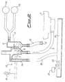
- the dishwasher tank 1 is connected to a tube 2, of any kind suitable for the purpose, whose upper end is inserted on a duct 3 which is part of a shaped hollow body 4.
- the duct 3 has its mouth located at a height corresponding to a level 5 which is the safety level for the water contained in the dishwasher tank 1.
- a float 6 is inserted inside duct 3 and vertically movable according to the water level therein.
- the hollow body 4 further includes a duct 9 through which clean water coming from the supply system flows over float 6.
- the hollow body 4 finally includes a chamber 10 provided with two outlets 10a, 10b and an inlet 10c, located below level 5, wherein a duct 11 is inserted whose mouth is located at the same height as the one of duct 3 and in communication therewith.
- the outlet 10b of chamber 10 is preferably connected to a drainpipe 12 whose opposite end is closed by a plug 13 whose function will be explained later on.
- the outlet 10a of chamber 10 is connected, on the contrary, to a safety manostat 14 and to an electropneumatic valve 15.
- the manostat 14 is capable of activating a discharge pump (not shown) for the emergency emptying of tank 1, while valve 15 is capable of stopping the water supply to the dishwasher.
- the dishwasher inlet manostat (not shown) controls the water supply to the machine and the level inside tank 1 is such as to keep float 6 at a height lower than switch 7.
- the float 6 is partially immersed in "dirty” water since the latter comes from tank 1, but it is continuously sprinkled by the clean water flowing down through duct 9. This flow of clean water prevents the accumulation on float 6 of washing residues forming encrustations which would weigh it down thus altering its functionality or could even block it.
- manostat 14 and valve 15 can not return to the condition corresponding to normal functioning of the dishwasher until the user, or preferably a technician, sees to the elimination of the excess water from chamber 10 by acting on plug 13, thus restoring the starting pressure value for the air contained therein.
- a second embodiment of the device according to the present invention which allows to get round a possible non-working of the safety manostat 14 and of valve 15.
- the non-working of manostat 14 and of valve 15 consequently causes the further increase of the water level, in particular inside the hollow body 4.
- said body also includes an emergency duct 16 whose mouth is located at a second safety level 17 higher than the first safety level 5.
- the second safety level 17 substantially can not get above it and is conveyed, through duct 16 and a tube 18 connected thereto, to a collecting tank 19 provided with a second float 20 which causes, when it is raised by the water discharged therein, the commutation of a microswitch 21 which controls the stopping of the water supply to the dishwasher.
- hollow body 4 may be made in any material and with any shape suitable for the purpose.
- a safety device with the above-described functionalities may also be obtained by assembling separate members to form a structure similar to that of the hollow body 4.
- the float 6 may be of any kind suitable for the described purpose and switch 7 may be of any kind suitable to detect the position of said float inside duct 3 of the device.
- the use of two or more switches 7 and of respective signals 8 may also be supposed in order to sense subsequent positions of float 6, while it is clear that plug 13 may be replaced by any member assuring the same functionality.
- the float 6 and respective switch 7 could also be located inside tank 1.
- float 6 and switch 7 it is also possible to completely eliminate float 6 and switch 7 by replacing them with a further chamber connected to a manostat, similar to chamber 10 connected to manostat 14.
- This additional chamber may be adjacent to duct 3 and in communication therewith, or it may be directly inside tank 1; in both instances the increase of water level would be detected by the manostat which would activate signals 8.
Landscapes
- Washing And Drying Of Tableware (AREA)
Abstract
A safety device for dishwashers, in particular for sensing high water consumption, including a duct (3), communicating with the machine tank (1), wherein a float (6) is housed whose rise is detected by a switch (7) which activates light and/or sound signals (8) to inform the user of an anomalous operating condition which anticipates the dishwasher emergency stop, said stop being controlled by the device through electropneumatic means (14, 15) and being reversible only following the intervention of an operator.
Description
- The present invention concerns the safety devices for dishwashing machines and in particular refers to a safety device for dishwashers for sensing anomalies in the water consumption.
- A number of devices are known suitable to sense an excessive accumulation of water in the tank of a dishwasher and to intervene, as a consequence thereof, by stopping the running of the machine.
- In particular, it is known a device including a duct in communication with the bottom of the dishwasher tank and whose upper end, located at a height corresponding with the maximum allowed water level, communicates through a siphon with an adjacent chamber provided with a sensor for detecting the pressure of the air contained therein. An excessive accumulation of water in the dishwasher tank, for example caused by the malfunctioning of the inlet manostat, implies the increase of the water level in said duct, and at the reaching of the emergency level a certain amount of water flows into said chamber compressing the air therein and causing, through the pressure sensor, the stop of the dishwasher.
- Since the malfunctionings which usually involve an excessive water consumption, and therefore an excessive accumulation thereof in the dishwasher, are usually not sudden but become progressively serious throughout a certain period of time corresponding to various operating cycles of the machine, the fact that the known device can only sense the reaching of an extreme condition considered dangerous is a serious drawback of the device.
- Another drawback of the known device arises from the fact that the excess water which has entered the controlled pressure chamber is automatically discharged, so that the dishwasher can be reactivated after an emergency stop without having eliminated the cause of the stop of the machine, and therefore in flooding risk conditions.
- The object of the present invention is therefore to provide a device capable of detecting and reporting a significant increase in the water consumption of a dishwasher before such an anomaly generates an emergency condition, and which is also capable of preventing the reactivation of the machine, after a possible emergency stop, until the manual intervention of an operator.
- This object is achieved by means of a device having the characteristics cited in claim 1.
- In addition to the above cited safety characteristics, the device according to the present invention has the advantage of providing, in one of its embodiments, a continuous flow of clean water on the float which is a fundamental part of the device, so as to avoid the formation of encrustations and the like which could alter the functioning of the float.
- These and other advantages and characteristics of the device according to the present invention will be apparent from the following detailed description of two embodiments referring to the annexed drawings wherein:
- Fig.1 is a schematic partially sectional view of a device according to the present invention; and
- Fig.2 is a view similar to the preceding one of a second embodiment.
- Referring to fig.1, there is seen that the dishwasher tank 1 is connected to a
tube 2, of any kind suitable for the purpose, whose upper end is inserted on a duct 3 which is part of a shaped hollow body 4. The duct 3 has its mouth located at a height corresponding to a level 5 which is the safety level for the water contained in the dishwasher tank 1. - A float 6 is inserted inside duct 3 and vertically movable according to the water level therein. A switch 7, preferably of electromagnetic type, capable of detecting the proximity of float 6 and of activating, as a consequence thereof, light and/or sound signals, schematized by the warning light 8, is mounted outside duct 3 below the safety level 5.
- The hollow body 4 further includes a duct 9 through which clean water coming from the supply system flows over float 6. The hollow body 4 finally includes a
chamber 10 provided with twooutlets 10a, 10b and aninlet 10c, located below level 5, wherein aduct 11 is inserted whose mouth is located at the same height as the one of duct 3 and in communication therewith. - The
outlet 10b ofchamber 10 is preferably connected to adrainpipe 12 whose opposite end is closed by aplug 13 whose function will be explained later on. - The outlet 10a of
chamber 10 is connected, on the contrary, to asafety manostat 14 and to anelectropneumatic valve 15. Themanostat 14 is capable of activating a discharge pump (not shown) for the emergency emptying of tank 1, whilevalve 15 is capable of stopping the water supply to the dishwasher. - In normal operating conditions, the dishwasher inlet manostat (not shown) controls the water supply to the machine and the level inside tank 1 is such as to keep float 6 at a height lower than switch 7. The float 6 is partially immersed in "dirty" water since the latter comes from tank 1, but it is continuously sprinkled by the clean water flowing down through duct 9. This flow of clean water prevents the accumulation on float 6 of washing residues forming encrustations which would weigh it down thus altering its functionality or could even block it.
- When, for any reason, the water level inside tank 1 increases, also float 6 rises inside duct 3 until it is detected by the electromagnetic switch 7 which, as already said, activates the light and/or sound signals 8. Therefore, the user is warned of the arising of an anomaly in the functioning of the dishwasher. At this moment the malfunctioning is not so serious as to justify the emergency stop of the machine, so that the dishwasher can regularly complete its operating cycle. Thus, there remains to the free choice of the user the further use of the machine in conditions which result economically and ecologically disadvantageous, since an excessive water consumption also involves a greater electric power consumption as well as significantly longer washing times.
- If the water level in tank 1 continues to rise, the same happens in duct 3 and on reaching level 5 the water flows into
duct 11 and after having filledpipe 12 starts to fillchamber 10 too. As a result, there is the compression of the air contained in the chamber which is connected tomanostat 14 and tovalve 15 through airtight connections. When water inchamber 10 reaches the safety level 5, the pressure of the overlying air activatesmanostat 14 andvalve 15, with the consequent emergency stop of the dishwasher. - It should be noted that
manostat 14 andvalve 15 can not return to the condition corresponding to normal functioning of the dishwasher until the user, or preferably a technician, sees to the elimination of the excess water fromchamber 10 by acting onplug 13, thus restoring the starting pressure value for the air contained therein. - Referring to fig.2, there is seen a second embodiment of the device according to the present invention which allows to get round a possible non-working of the
safety manostat 14 and ofvalve 15. In fact, in case the water in tank 1 has reached the safety level 5, the non-working ofmanostat 14 and ofvalve 15 consequently causes the further increase of the water level, in particular inside the hollow body 4. In this instance, however, said body also includes anemergency duct 16 whose mouth is located at a second safety level 17 higher than the first safety level 5. - Therefore, if the water reaches the second safety level 17 substantially can not get above it and is conveyed, through
duct 16 and atube 18 connected thereto, to a collectingtank 19 provided with asecond float 20 which causes, when it is raised by the water discharged therein, the commutation of amicroswitch 21 which controls the stopping of the water supply to the dishwasher. - It is clear that the hollow body 4 may be made in any material and with any shape suitable for the purpose.
- A safety device with the above-described functionalities may also be obtained by assembling separate members to form a structure similar to that of the hollow body 4.
- The float 6 may be of any kind suitable for the described purpose and switch 7 may be of any kind suitable to detect the position of said float inside duct 3 of the device. The use of two or more switches 7 and of respective signals 8 may also be supposed in order to sense subsequent positions of float 6, while it is clear that
plug 13 may be replaced by any member assuring the same functionality. The float 6 and respective switch 7 could also be located inside tank 1. - It is also possible to completely eliminate float 6 and switch 7 by replacing them with a further chamber connected to a manostat, similar to
chamber 10 connected tomanostat 14. This additional chamber may be adjacent to duct 3 and in communication therewith, or it may be directly inside tank 1; in both instances the increase of water level would be detected by the manostat which would activate signals 8. - Therefore, these and other changes may be made to the device according to the present invention by those skilled in the art yet remaining within the scope of the invention.
Claims (10)
- A safety device for dishwashers including a duct (3) communicating with the tank (1) of the machine and having its mouth at a height corresponding to a safety level (5) of the water contained in said tank (1), above which the water flows into an airtight chamber (10) in communication with the duct (3) and connected to pneumatic means (14, 15) suitable to carry out the emergency stop of the machine, said device being characterized in that it includes means suitable to sense the increase of the water level before it reaches said safety level (5) as well as suitable to activate signals (8) of light and /or sound type, said chamber (10) being provided with a drainpipe which can be opened only on command of an operator.
- A device according to claim 1, characterized in that said sensing means consist of a float (6) and one or more switches (7) suitable to sense the position of said float (6).
- A device according to claim 2, characterized in that the float (6) is located inside the duct (3).
- A device according to claim 3, characterized in that the float (6) is continuously sprinkled from above by water directly taken from the supply system through a second duct (9) connected to the duct (3).
- A device according to claim 2, characterized in that the float (6) is located inside the tank (1).
- A device according to claim 1, characterized in that said sensing means consist of an airtight chamber (10) connected to a manostat (14).
- A device according to claim 6, characterized in that the airtight chamber (10) is in communication with the duct (3).
- A device according to claim 6, characterized in that the airtight chamber (10) is located inside the tank (1) and in communication therewith.
- A device according to one of the preceding claims, characterized in that it also includes a third duct (16), in communication with the duct (3), whose mouth is located at a height corresponding to a second safety level (17), higher than the first safety level (5), and is in communication with a collecting tank (19) provided with electromechanical means (20, 21) suitable to carry out the emergency stop of the machine.
- A dishwasher provided with a device according to one of the preceding claims.
Applications Claiming Priority (2)
| Application Number | Priority Date | Filing Date | Title |
|---|---|---|---|
| ITMI921768 | 1992-07-22 | ||
| ITMI921768A IT1256122B (en) | 1992-07-22 | 1992-07-22 | SAFETY DEVICE FOR DISHWASHER, IN PARTICULAR FOR THE DETECTION OF HIGH WATER CONSUMPTION |
Publications (1)
| Publication Number | Publication Date |
|---|---|
| EP0580563A1 true EP0580563A1 (en) | 1994-01-26 |
Family
ID=11363707
Family Applications (1)
| Application Number | Title | Priority Date | Filing Date |
|---|---|---|---|
| EP93830318A Withdrawn EP0580563A1 (en) | 1992-07-22 | 1993-07-21 | Safety device for dishwashers, in particular for sensing high water consumption |
Country Status (2)
| Country | Link |
|---|---|
| EP (1) | EP0580563A1 (en) |
| IT (1) | IT1256122B (en) |
Cited By (2)
| Publication number | Priority date | Publication date | Assignee | Title |
|---|---|---|---|---|
| EP1532917A1 (en) * | 2003-11-21 | 2005-05-25 | Electrolux Home Products Corporation N.V. | Household-type dishwashing machine with improved light indicators |
| CN104545748A (en) * | 2014-12-31 | 2015-04-29 | 宁波方太厨具有限公司 | Overflow protection device of water tank type cleaning machine |
Citations (8)
| Publication number | Priority date | Publication date | Assignee | Title |
|---|---|---|---|---|
| GB1192125A (en) * | 1968-09-25 | 1970-05-20 | Philips Electronic Associated | Improvements in or relating to Dish-Washing Machines |
| GB1267737A (en) * | 1968-05-15 | 1972-03-22 | Zanussi A Spa Industrie | An improved dishwashing or other washing machine |
| US3986372A (en) * | 1976-01-16 | 1976-10-19 | Whirlpool Corporation | Appliance programmer including a safety circuit |
| EP0017453A1 (en) * | 1979-04-02 | 1980-10-15 | Eaton Corporation | Washing appliance and liquid level sensing means therefor |
| EP0028067A1 (en) * | 1979-09-12 | 1981-05-06 | Kenwood Manufacturing Company Limited | Washing machine having drain blockage indicator |
| EP0439397A1 (en) * | 1990-01-26 | 1991-07-31 | Esswein S.A. | Water level control in a household appliance and machine provided with such a device |
| EP0461722A1 (en) * | 1990-06-15 | 1991-12-18 | Bauknecht Hausgeräte GmbH | Inlet quantity control for dish washers and washing machines |
| WO1992004855A1 (en) * | 1990-09-18 | 1992-04-02 | Bosch-Siemens Hausgeräte Gmbh | Safety device for domestic appliances through which water flows |
-
1992
- 1992-07-22 IT ITMI921768A patent/IT1256122B/en active IP Right Grant
-
1993
- 1993-07-21 EP EP93830318A patent/EP0580563A1/en not_active Withdrawn
Patent Citations (8)
| Publication number | Priority date | Publication date | Assignee | Title |
|---|---|---|---|---|
| GB1267737A (en) * | 1968-05-15 | 1972-03-22 | Zanussi A Spa Industrie | An improved dishwashing or other washing machine |
| GB1192125A (en) * | 1968-09-25 | 1970-05-20 | Philips Electronic Associated | Improvements in or relating to Dish-Washing Machines |
| US3986372A (en) * | 1976-01-16 | 1976-10-19 | Whirlpool Corporation | Appliance programmer including a safety circuit |
| EP0017453A1 (en) * | 1979-04-02 | 1980-10-15 | Eaton Corporation | Washing appliance and liquid level sensing means therefor |
| EP0028067A1 (en) * | 1979-09-12 | 1981-05-06 | Kenwood Manufacturing Company Limited | Washing machine having drain blockage indicator |
| EP0439397A1 (en) * | 1990-01-26 | 1991-07-31 | Esswein S.A. | Water level control in a household appliance and machine provided with such a device |
| EP0461722A1 (en) * | 1990-06-15 | 1991-12-18 | Bauknecht Hausgeräte GmbH | Inlet quantity control for dish washers and washing machines |
| WO1992004855A1 (en) * | 1990-09-18 | 1992-04-02 | Bosch-Siemens Hausgeräte Gmbh | Safety device for domestic appliances through which water flows |
Non-Patent Citations (1)
| Title |
|---|
| PATENT ABSTRACTS OF JAPAN vol. 014, no. 299 (C-733)1990 & JP-A-02 098 332 ( MITSUBISHI ELECTRIC CORP. ) * |
Cited By (2)
| Publication number | Priority date | Publication date | Assignee | Title |
|---|---|---|---|---|
| EP1532917A1 (en) * | 2003-11-21 | 2005-05-25 | Electrolux Home Products Corporation N.V. | Household-type dishwashing machine with improved light indicators |
| CN104545748A (en) * | 2014-12-31 | 2015-04-29 | 宁波方太厨具有限公司 | Overflow protection device of water tank type cleaning machine |
Also Published As
| Publication number | Publication date |
|---|---|
| IT1256122B (en) | 1995-11-29 |
| ITMI921768A0 (en) | 1992-07-22 |
| ITMI921768A1 (en) | 1994-01-22 |
Similar Documents
| Publication | Publication Date | Title |
|---|---|---|
| GB1586342A (en) | Washing machine | |
| KR950014659B1 (en) | Safety device for domestic appliances through which water flows | |
| ITMI951271A1 (en) | DEVICE TO CHECK THE WASHING OF THE FILTER OF A DISHWASHER MACHINE | |
| US3885580A (en) | Dishwasher control system | |
| CA2015958C (en) | Coffee or tea machine | |
| EP1363527B1 (en) | A water level indicating device for a dishwasher | |
| US3656866A (en) | Drain pump control | |
| GB2166645A (en) | Water inflow control in an appliance operable with water | |
| EP0669099B1 (en) | Device for controlling the level of washing liquid in a dishwasher | |
| EP0753281A1 (en) | A device for controlling the level of feed water of dishwasher machines and the like | |
| EP0710464B1 (en) | Device for controlling the feed of washing liquid in a dishwasher machine | |
| EP0685198B1 (en) | Control device for feeding differentiated volumes of washing liquid in a dishwasher | |
| GB2067891A (en) | Dishwashing machine | |
| US4132936A (en) | Condensate discharge apparatus | |
| US4684327A (en) | Washing machine fluid discharge monitoring unit | |
| JPS5995098A (en) | Washer | |
| GB2090874A (en) | Automatic washing machine with improved water supply circuit | |
| CN220013892U (en) | Drainer and integrated water tank | |
| EP0022911B1 (en) | Washing machine provided with a device for preventing backflow of water | |
| EP0931503A2 (en) | Device for controlling and restoring the water level in a dishwashing machine | |
| KR0136456Y1 (en) | Water level detector for dish washer | |
| KR0140595B1 (en) | Abnormal water level detector for dish washer | |
| EP0947156A1 (en) | Device for the liquid supply and dosage in a domestic washing machine tub, in particular a dishwashing machine | |
| GB2225934A (en) | Regulating water supply to dishwashing and laundry washing machines | |
| GB2144031A (en) | Dishwashing machine |
Legal Events
| Date | Code | Title | Description |
|---|---|---|---|
| PUAI | Public reference made under article 153(3) epc to a published international application that has entered the european phase |
Free format text: ORIGINAL CODE: 0009012 |
|
| AK | Designated contracting states |
Kind code of ref document: A1 Designated state(s): AT CH DE ES FR GB IT LI SE |
|
| 17P | Request for examination filed |
Effective date: 19940422 |
|
| 17Q | First examination report despatched |
Effective date: 19950816 |
|
| STAA | Information on the status of an ep patent application or granted ep patent |
Free format text: STATUS: THE APPLICATION IS DEEMED TO BE WITHDRAWN |
|
| 18D | Application deemed to be withdrawn |
Effective date: 19960227 |