EP0580537A2 - Improved cramp for joining modular form panels - Google Patents
Improved cramp for joining modular form panels Download PDFInfo
- Publication number
- EP0580537A2 EP0580537A2 EP93500004A EP93500004A EP0580537A2 EP 0580537 A2 EP0580537 A2 EP 0580537A2 EP 93500004 A EP93500004 A EP 93500004A EP 93500004 A EP93500004 A EP 93500004A EP 0580537 A2 EP0580537 A2 EP 0580537A2
- Authority
- EP
- European Patent Office
- Prior art keywords
- jaws
- section
- wedge
- cramp
- mounting section
- Prior art date
- Legal status (The legal status is an assumption and is not a legal conclusion. Google has not performed a legal analysis and makes no representation as to the accuracy of the status listed.)
- Granted
Links
Images

Classifications
-
- B—PERFORMING OPERATIONS; TRANSPORTING
- B07—SEPARATING SOLIDS FROM SOLIDS; SORTING
- B07B—SEPARATING SOLIDS FROM SOLIDS BY SIEVING, SCREENING, SIFTING OR BY USING GAS CURRENTS; SEPARATING BY OTHER DRY METHODS APPLICABLE TO BULK MATERIAL, e.g. LOOSE ARTICLES FIT TO BE HANDLED LIKE BULK MATERIAL
- B07B1/00—Sieving, screening, sifting, or sorting solid materials using networks, gratings, grids, or the like
- B07B1/46—Constructional details of screens in general; Cleaning or heating of screens
- B07B1/4609—Constructional details of screens in general; Cleaning or heating of screens constructional details of screening surfaces or meshes
- B07B1/4645—Screening surfaces built up of modular elements
-
- E—FIXED CONSTRUCTIONS
- E04—BUILDING
- E04G—SCAFFOLDING; FORMS; SHUTTERING; BUILDING IMPLEMENTS OR AIDS, OR THEIR USE; HANDLING BUILDING MATERIALS ON THE SITE; REPAIRING, BREAKING-UP OR OTHER WORK ON EXISTING BUILDINGS
- E04G17/00—Connecting or other auxiliary members for forms, falsework structures, or shutterings
- E04G17/04—Connecting or fastening means for metallic forming or stiffening elements, e.g. for connecting metallic elements to non-metallic elements
- E04G17/045—Connecting or fastening means for metallic forming or stiffening elements, e.g. for connecting metallic elements to non-metallic elements being tensioned by wedge-shaped elements
-
- E—FIXED CONSTRUCTIONS
- E04—BUILDING
- E04G—SCAFFOLDING; FORMS; SHUTTERING; BUILDING IMPLEMENTS OR AIDS, OR THEIR USE; HANDLING BUILDING MATERIALS ON THE SITE; REPAIRING, BREAKING-UP OR OTHER WORK ON EXISTING BUILDINGS
- E04G9/00—Forming or shuttering elements for general use
- E04G9/02—Forming boards or similar elements
- E04G2009/023—Forming boards or similar elements with edge protection
- E04G2009/025—Forming boards or similar elements with edge protection by a flange of the board's frame
Definitions
- the invention relates to a cramp with which modular form panels can be joined to each other simply, efficiently and rapidly, the cramp comprising a pair of jaws that clasp and clamp the frame sections of the boards to join, one of the jaws being displaceable and hence travelling to and from the other, clamping being effected by a simple wedge.
- the cramp subject hereof is based upon the above-mentioned type of structure, i.e. it comprises three parts that will hereinafter be designated “male part”, “female part” and “wedge” or mounting pin, and is characteristic in that the male part, which comprises two mounting jaws that are defined by two wings integral with a mounting section, has a heel at its free end facing another heel with which the two jaws in the female part are provided, the female part comprising a U-section that clasps and travels along the above-mentioned mounting section, guiding itself on the same because the two jaws on this female or travelling part have two inwardly projecting bolts reaching into grooves provided to such end on the mounting section, thereby acting as guide means for the said female part and moreover a pivoting means therefor.
- the two lateral faces upon which the jaws of both male and female parts and of the mounting section are moreover positioned, are provided with two longitudinal windows with notches towards either side, the aim being for the notches to be slanting and offset on one side with regard to the other in order to obtain a perfect fit for the relevant wedge or mounting pin, such comprising a lowered T-section with what could be designated the transverse branch having a skew longitudinal edge.
- This wedge crosses not only the windows provided on the sides of the mounting section but naturally also the windows provided on the side wings of the female part, i.e. the windows backed to and clasping the sides of the mounting section, one of the windows being singularly rectangular and the one opposite being provided with a notch on one of the end sides to house the edge of the skew wedge wing.
- the sections of the panels to join will be located between the facing jaws and clamping will be effected by merely inserting the wedge across the facing windows of the female part and the male part, i.e. in the latter case of the mounting section, so that as the wedge is pushed the travelling jaw or female part will move and clamping will take place, as appropriate.
- the wedge or mounting pin has a tailpiece or transverse projection at its free end to prevent the said wedge from becoming detached once the aforesaid three-part assembly is mounted.
- Figure 1.- Is a side elevation view of the cramp joining the two modular form panel sections to each other.
- Figure 2. Is a plan view of the actual cramp, the dash line showing the slanting and offset notches that form part of the longitudinal window provided on either side of the mounting section, the said figure also showing the peculiar shape of the actual mounting pin or wedge.
- Figure 3.- Is a profile view of the assembly shown in the above figure.
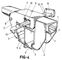
- Figure 4.- Is finally a general perspective view of the cramp of the invention joining the sections of two adjacent panels to each other, as shown in figure 1.
- the cramp of the invention has a male part comprising a peculiarly shaped tubular section (1) and a pair of jaws (2) integral with two of the sides of the mounting section (1), the latter also having on what could be considered the lower edge of such sides where the jaws (2) are fixed, two steps (1') the purpose of which will be described hereinafter.
- the jaws (2) have heels (3) at their free end that shall reach into grooves or recesses (4') in the very sections (4) of the modular panels to join, as clearly shown in figures (1) and (4).
- the sides of the mounting section (1) with which the two jaws (2) are integral are further provided with an elongate window (5) with notches on its longitudinal edges making up successive T shapes, thereby for these notches, with reference number (6), to be slanting and slightly offset, as shown in figure 2.
- the cramp is additionally provided with a second travelling part having two further jaws (7) identical to jaws (2) and likewise provided with the relevant heels (3) at their ends, the jaws (7) projecting from the ends of a U-section (7') that clasps and travels along section (1).
- the cramp is further provided with a third part that consists of a pin or wedge (8) shaped and working as described hereinafter.
- the inner face of the jaws (7) is provided with two bolts (9) that reach into the steps (1') on the mounting section (1), such steps (1') constituting the guiding means for the part comprising the jaws (7) and the U-section (7') from which they project to travel as a whole, preventing run-off during travel from the mounting section (1) and allowing the female part to pivot about the said bolts (9).
- the side wings of the U-section (7') are provided with a rectangular window (10) and one of these is recessed at one of its shorter sides, which recess naturally faces the window (5) provided on that side of the mounting section (1).
- the wedge or cross pin (8) is T-shaped and one of its branches (11) has its slanting longitudinal edge precisely acting as a wedge while the other branch defines ribs on either side which adjust to and are positioned in the notches of the window (5) of the side wings of the mounting section (1), the said pin or wedge (8) also having a tailpiece (13) that prevents the same from becoming detached once the said three parts are mounted.
- one of the windows (10) on the sides of the female or travelling part (7') is provided at one of its end sides, namely on the skew edge of the wing (11), with a central expansion-like notch, of considerably smaller width than the actual window (10), that is precisely positioned on the skew edge of the wedge (8) wing (11).
Landscapes
- Engineering & Computer Science (AREA)
- Architecture (AREA)
- Mechanical Engineering (AREA)
- Civil Engineering (AREA)
- Structural Engineering (AREA)
- Mutual Connection Of Rods And Tubes (AREA)
- Forms Removed On Construction Sites Or Auxiliary Members Thereof (AREA)
- Vessels, Lead-In Wires, Accessory Apparatuses For Cathode-Ray Tubes (AREA)
- Connection Of Plates (AREA)
Abstract
Description
- The invention relates to a cramp with which modular form panels can be joined to each other simply, efficiently and rapidly, the cramp comprising a pair of jaws that clasp and clamp the frame sections of the boards to join, one of the jaws being displaceable and hence travelling to and from the other, clamping being effected by a simple wedge.
- Many kinds of cramps are currently known and sold with which to fix or hold form module panels to each other. Of these, a particular type can be referred to provided with two jaws that have their facing edges stepped to hold the panel frame sections, with one of the jaws travelling along a mounting section to which the other jaw is fixed, and locked in a mounting position by a cross pin.
- A number of problems and disadvantages are none the less derived from the above, namely a complex overall structure, a pin that is scarcely reliable in its final locking, and the jaws section is barely rational, which all leads not only to an economical cost in obtaining the cramp but to a product that can be improved to obtain a far better performance.
- The cramp subject hereof is based upon the above-mentioned type of structure, i.e. it comprises three parts that will hereinafter be designated "male part", "female part" and "wedge" or mounting pin, and is characteristic in that the male part, which comprises two mounting jaws that are defined by two wings integral with a mounting section, has a heel at its free end facing another heel with which the two jaws in the female part are provided, the female part comprising a U-section that clasps and travels along the above-mentioned mounting section, guiding itself on the same because the two jaws on this female or travelling part have two inwardly projecting bolts reaching into grooves provided to such end on the mounting section, thereby acting as guide means for the said female part and moreover a pivoting means therefor. The two lateral faces upon which the jaws of both male and female parts and of the mounting section are moreover positioned, are provided with two longitudinal windows with notches towards either side, the aim being for the notches to be slanting and offset on one side with regard to the other in order to obtain a perfect fit for the relevant wedge or mounting pin, such comprising a lowered T-section with what could be designated the transverse branch having a skew longitudinal edge. This wedge crosses not only the windows provided on the sides of the mounting section but naturally also the windows provided on the side wings of the female part, i.e. the windows backed to and clasping the sides of the mounting section, one of the windows being singularly rectangular and the one opposite being provided with a notch on one of the end sides to house the edge of the skew wedge wing.
- Thus, the sections of the panels to join will be located between the facing jaws and clamping will be effected by merely inserting the wedge across the facing windows of the female part and the male part, i.e. in the latter case of the mounting section, so that as the wedge is pushed the travelling jaw or female part will move and clamping will take place, as appropriate.
- It should also be noted that the wedge or mounting pin has a tailpiece or transverse projection at its free end to prevent the said wedge from becoming detached once the aforesaid three-part assembly is mounted.
- In order to provide a fuller description and contribute to the complete understanding of the characteristics of this invention, a set of drawings is attached to the specification which, while purely illustrative and not fully comprehensive, shows the following:
- Figure 1.- Is a side elevation view of the cramp joining the two modular form panel sections to each other.
- Figure 2.- Is a plan view of the actual cramp, the dash line showing the slanting and offset notches that form part of the longitudinal window provided on either side of the mounting section, the said figure also showing the peculiar shape of the actual mounting pin or wedge.
- Figure 3.- Is a profile view of the assembly shown in the above figure.
- Figure 4.- Is finally a general perspective view of the cramp of the invention joining the sections of two adjacent panels to each other, as shown in figure 1.
- It is clear in light of the said figures that the cramp of the invention has a male part comprising a peculiarly shaped tubular section (1) and a pair of jaws (2) integral with two of the sides of the mounting section (1), the latter also having on what could be considered the lower edge of such sides where the jaws (2) are fixed, two steps (1') the purpose of which will be described hereinafter. The jaws (2) have heels (3) at their free end that shall reach into grooves or recesses (4') in the very sections (4) of the modular panels to join, as clearly shown in figures (1) and (4).
- The sides of the mounting section (1) with which the two jaws (2) are integral are further provided with an elongate window (5) with notches on its longitudinal edges making up successive T shapes, thereby for these notches, with reference number (6), to be slanting and slightly offset, as shown in figure 2.
- The cramp is additionally provided with a second travelling part having two further jaws (7) identical to jaws (2) and likewise provided with the relevant heels (3) at their ends, the jaws (7) projecting from the ends of a U-section (7') that clasps and travels along section (1).
- The cramp is further provided with a third part that consists of a pin or wedge (8) shaped and working as described hereinafter.
- The inner face of the jaws (7) is provided with two bolts (9) that reach into the steps (1') on the mounting section (1), such steps (1') constituting the guiding means for the part comprising the jaws (7) and the U-section (7') from which they project to travel as a whole, preventing run-off during travel from the mounting section (1) and allowing the female part to pivot about the said bolts (9).
- The side wings of the U-section (7') are provided with a rectangular window (10) and one of these is recessed at one of its shorter sides, which recess naturally faces the window (5) provided on that side of the mounting section (1).
- The wedge or cross pin (8) is T-shaped and one of its branches (11) has its slanting longitudinal edge precisely acting as a wedge while the other branch defines ribs on either side which adjust to and are positioned in the notches of the window (5) of the side wings of the mounting section (1), the said pin or wedge (8) also having a tailpiece (13) that prevents the same from becoming detached once the said three parts are mounted.
- In accordance with this structure when two modular form panels are to be joined to each other, with adjacent sections referred to as number (4) in figures 1 and 2, the jaws (2) and (7) shall face one another, and their heels (3) will be housed in the recesses or grooves (4') of the said sections (4) to join, whereupon the wedge (8) will be pushed to travel along the said notches (6) in the windows (5) of the mounting section (1), and the slanting and offset layout of the notches (6) will cause the wedge to drive or draw the female part and namely the travelling jaws (7) along the section (1), thereby for both sections (4) to be clamped and hence joined to one another.
- It should finally be said that one of the windows (10) on the sides of the female or travelling part (7') is provided at one of its end sides, namely on the skew edge of the wing (11), with a central expansion-like notch, of considerably smaller width than the actual window (10), that is precisely positioned on the skew edge of the wedge (8) wing (11).
Claims (3)
Applications Claiming Priority (2)
| Application Number | Priority Date | Filing Date | Title |
|---|---|---|---|
| ES09201525A ES2066676B1 (en) | 1992-07-21 | 1992-07-21 | PERFECTED STAPLE FOR THE JOINT OF MODULAR FORMWORK PANELS. |
| ES9201525 | 1992-07-21 |
Publications (3)
| Publication Number | Publication Date |
|---|---|
| EP0580537A2 true EP0580537A2 (en) | 1994-01-26 |
| EP0580537A3 EP0580537A3 (en) | 1995-03-15 |
| EP0580537B1 EP0580537B1 (en) | 1997-08-20 |
Family
ID=8277731
Family Applications (1)
| Application Number | Title | Priority Date | Filing Date |
|---|---|---|---|
| EP93500004A Expired - Lifetime EP0580537B1 (en) | 1992-07-21 | 1993-01-21 | Improved cramp for joining modular form panels |
Country Status (3)
| Country | Link |
|---|---|
| EP (1) | EP0580537B1 (en) |
| DE (1) | DE69313213T2 (en) |
| ES (1) | ES2066676B1 (en) |
Cited By (7)
| Publication number | Priority date | Publication date | Assignee | Title |
|---|---|---|---|---|
| FR2738859A1 (en) * | 1995-09-14 | 1997-03-21 | Deko | Pincers for assembling concrete shuttering panels |
| WO2001063073A1 (en) * | 2000-02-24 | 2001-08-30 | Bauma S.A. | A lock for connecting boarding plates |
| WO2005007997A1 (en) | 2003-07-11 | 2005-01-27 | Peri Gmbh | Clamping lock device comprising an obliquely guided wedge |
| WO2006108893A1 (en) * | 2005-04-11 | 2006-10-19 | Sistemas Tecnicos De Encofrados, S.A. | Clamp for securing shuttering panels |
| EP2039849A3 (en) * | 2007-09-19 | 2013-01-16 | Condor Group S.p.A. | Device for blocking formworks |
| ITUA20162408A1 (en) * | 2016-04-08 | 2017-10-08 | Faresin Building S P A | CONNECTION DEVICE FOR TWO COMPONENTS OF A CASSERATION SYSTEM |
| WO2020201274A1 (en) * | 2019-04-05 | 2020-10-08 | Paschal-Werk G. Maier Gmbh | Connecting clip and formwork element having a connecting clip |
Families Citing this family (1)
| Publication number | Priority date | Publication date | Assignee | Title |
|---|---|---|---|---|
| RU2385396C1 (en) * | 2008-08-19 | 2010-03-27 | Роман Вадимович Кузнецов | Lock for attaching formwork elements |
Family Cites Families (3)
| Publication number | Priority date | Publication date | Assignee | Title |
|---|---|---|---|---|
| US3481575A (en) * | 1967-04-03 | 1969-12-02 | Rocform Corp | Prefabricated wall form |
| DE3545273C3 (en) * | 1985-12-20 | 1995-09-07 | Peri Werk Schwoerer Kg Artur | Turnbuckle device for concrete formwork elements |
| DE3734390C2 (en) * | 1987-10-10 | 1993-10-28 | Gerhard Dingler | Composite for formwork |
-
1992
- 1992-07-21 ES ES09201525A patent/ES2066676B1/en not_active Expired - Fee Related
-
1993
- 1993-01-21 EP EP93500004A patent/EP0580537B1/en not_active Expired - Lifetime
- 1993-01-21 DE DE69313213T patent/DE69313213T2/en not_active Expired - Fee Related
Cited By (9)
| Publication number | Priority date | Publication date | Assignee | Title |
|---|---|---|---|---|
| FR2738859A1 (en) * | 1995-09-14 | 1997-03-21 | Deko | Pincers for assembling concrete shuttering panels |
| WO2001063073A1 (en) * | 2000-02-24 | 2001-08-30 | Bauma S.A. | A lock for connecting boarding plates |
| WO2005007997A1 (en) | 2003-07-11 | 2005-01-27 | Peri Gmbh | Clamping lock device comprising an obliquely guided wedge |
| US8104738B2 (en) * | 2003-07-11 | 2012-01-31 | Peri Gmbh | Concrete shell system including clamping devices having diagonally guided wedges |
| WO2006108893A1 (en) * | 2005-04-11 | 2006-10-19 | Sistemas Tecnicos De Encofrados, S.A. | Clamp for securing shuttering panels |
| US7966703B2 (en) | 2005-04-11 | 2011-06-28 | Sistemas Tecnicos De Encofrados, S.A. | Clamp for securing shuttering panels |
| EP2039849A3 (en) * | 2007-09-19 | 2013-01-16 | Condor Group S.p.A. | Device for blocking formworks |
| ITUA20162408A1 (en) * | 2016-04-08 | 2017-10-08 | Faresin Building S P A | CONNECTION DEVICE FOR TWO COMPONENTS OF A CASSERATION SYSTEM |
| WO2020201274A1 (en) * | 2019-04-05 | 2020-10-08 | Paschal-Werk G. Maier Gmbh | Connecting clip and formwork element having a connecting clip |
Also Published As
| Publication number | Publication date |
|---|---|
| DE69313213T2 (en) | 1998-01-02 |
| DE69313213D1 (en) | 1997-09-25 |
| ES2066676R (en) | 1997-01-16 |
| EP0580537A3 (en) | 1995-03-15 |
| ES2066676A2 (en) | 1995-03-01 |
| EP0580537B1 (en) | 1997-08-20 |
| ES2066676B1 (en) | 1997-07-16 |
Similar Documents
| Publication | Publication Date | Title |
|---|---|---|
| KR100225876B1 (en) | Lock Slider for Slide Fasteners | |
| US6128881A (en) | Portable floor | |
| EP0580537B1 (en) | Improved cramp for joining modular form panels | |
| CA2312822A1 (en) | Method for laying and interlocking panels | |
| PT1335453E (en) | Electrical splice connector | |
| US20090293403A1 (en) | Connections for suspended ceiling system | |
| DE203904T1 (en) | FORMWORK AND REINFORCEMENT WALL. | |
| DE69208989T2 (en) | Skeleton profile with an arrangement of accessories | |
| US4839472A (en) | Closure system for a longitudinally divided cable sleeve | |
| CA2051315A1 (en) | Casement frame clip assembly | |
| DE3872821T2 (en) | BUCKLE. | |
| KR950001609Y1 (en) | Slider for closing coupling elements | |
| KR940005248A (en) | Slide fastener and manufacturing method thereof | |
| KR870002381Y1 (en) | Slide fasteners | |
| DE2609388B2 (en) | Stabilization and alignment element for miter joints between two construction profiles | |
| DE3218184C2 (en) | Interior light for vehicles | |
| DE2723287A1 (en) | SCRUB, OR SKIRTING, PREFERABLY MADE OF SYNTHETIC MATERIAL | |
| DE2022009C3 (en) | Arrangement for the detachable connection of two channel-shaped profile parts facing each other with their longitudinal opening, in particular in the case of a lamp for fluorescent tubes | |
| DE19715247C1 (en) | Composite frame, particularly for door | |
| DE4002476C1 (en) | ||
| NO161014B (en) | Insulating composite profile for windows, doors or facades. | |
| DE3436201A1 (en) | COMPONENT | |
| DE3402174A1 (en) | Corner connection for frames, in particular heat-insulated, metal frames, of doors, windows or the like | |
| DE2617228C3 (en) | End bracket with shield cap | |
| DE19956441A1 (en) | Clamp for insulating glass pane in frame incorporates blocks in pockets, insert in profiled grove, protective plate, and link |
Legal Events
| Date | Code | Title | Description |
|---|---|---|---|
| PUAI | Public reference made under article 153(3) epc to a published international application that has entered the european phase |
Free format text: ORIGINAL CODE: 0009012 |
|
| AK | Designated contracting states |
Kind code of ref document: A2 Designated state(s): DE FR GB IT PT |
|
| PUAL | Search report despatched |
Free format text: ORIGINAL CODE: 0009013 |
|
| AK | Designated contracting states |
Kind code of ref document: A3 Designated state(s): DE FR GB IT PT |
|
| 17P | Request for examination filed |
Effective date: 19950427 |
|
| GRAG | Despatch of communication of intention to grant |
Free format text: ORIGINAL CODE: EPIDOS AGRA |
|
| 17Q | First examination report despatched |
Effective date: 19961011 |
|
| GRAH | Despatch of communication of intention to grant a patent |
Free format text: ORIGINAL CODE: EPIDOS IGRA |
|
| GRAH | Despatch of communication of intention to grant a patent |
Free format text: ORIGINAL CODE: EPIDOS IGRA |
|
| GRAA | (expected) grant |
Free format text: ORIGINAL CODE: 0009210 |
|
| RAP1 | Party data changed (applicant data changed or rights of an application transferred) |
Owner name: ULMA C Y E, S. COOP. |
|
| AK | Designated contracting states |
Kind code of ref document: B1 Designated state(s): DE FR GB IT PT |
|
| ET | Fr: translation filed | ||
| REF | Corresponds to: |
Ref document number: 69313213 Country of ref document: DE Date of ref document: 19970925 |
|
| ITF | It: translation for a ep patent filed | ||
| REG | Reference to a national code |
Ref country code: PT Ref legal event code: SC4A Free format text: AVAILABILITY OF NATIONAL TRANSLATION Effective date: 19971031 |
|
| PLBQ | Unpublished change to opponent data |
Free format text: ORIGINAL CODE: EPIDOS OPPO |
|
| PLBI | Opposition filed |
Free format text: ORIGINAL CODE: 0009260 |
|
| PLBF | Reply of patent proprietor to notice(s) of opposition |
Free format text: ORIGINAL CODE: EPIDOS OBSO |
|
| 26 | Opposition filed |
Opponent name: PERI GMBH Effective date: 19980516 |
|
| PLBF | Reply of patent proprietor to notice(s) of opposition |
Free format text: ORIGINAL CODE: EPIDOS OBSO |
|
| PLBO | Opposition rejected |
Free format text: ORIGINAL CODE: EPIDOS REJO |
|
| APAC | Appeal dossier modified |
Free format text: ORIGINAL CODE: EPIDOS NOAPO |
|
| APAE | Appeal reference modified |
Free format text: ORIGINAL CODE: EPIDOS REFNO |
|
| APAC | Appeal dossier modified |
Free format text: ORIGINAL CODE: EPIDOS NOAPO |
|
| APCC | Communication from the board of appeal sent |
Free format text: ORIGINAL CODE: EPIDOS OBAPO |
|
| REG | Reference to a national code |
Ref country code: GB Ref legal event code: IF02 |
|
| APAC | Appeal dossier modified |
Free format text: ORIGINAL CODE: EPIDOS NOAPO |
|
| PLBN | Opposition rejected |
Free format text: ORIGINAL CODE: 0009273 |
|
| STAA | Information on the status of an ep patent application or granted ep patent |
Free format text: STATUS: OPPOSITION REJECTED |
|
| 27O | Opposition rejected |
Effective date: 19990920 |
|
| APAH | Appeal reference modified |
Free format text: ORIGINAL CODE: EPIDOSCREFNO |
|
| PGFP | Annual fee paid to national office [announced via postgrant information from national office to epo] |
Ref country code: GB Payment date: 20060109 Year of fee payment: 14 |
|
| GBPC | Gb: european patent ceased through non-payment of renewal fee |
Effective date: 20070121 |
|
| PG25 | Lapsed in a contracting state [announced via postgrant information from national office to epo] |
Ref country code: GB Free format text: LAPSE BECAUSE OF NON-PAYMENT OF DUE FEES Effective date: 20070121 |
|
| PGFP | Annual fee paid to national office [announced via postgrant information from national office to epo] |
Ref country code: PT Payment date: 20090119 Year of fee payment: 17 Ref country code: DE Payment date: 20090123 Year of fee payment: 17 |
|
| PGFP | Annual fee paid to national office [announced via postgrant information from national office to epo] |
Ref country code: IT Payment date: 20090128 Year of fee payment: 17 |
|
| PGFP | Annual fee paid to national office [announced via postgrant information from national office to epo] |
Ref country code: FR Payment date: 20090129 Year of fee payment: 17 |
|
| REG | Reference to a national code |
Ref country code: PT Ref legal event code: MM4A Free format text: LAPSE DUE TO NON-PAYMENT OF FEES Effective date: 20100721 |
|
| REG | Reference to a national code |
Ref country code: FR Ref legal event code: ST Effective date: 20100930 |
|
| PG25 | Lapsed in a contracting state [announced via postgrant information from national office to epo] |
Ref country code: FR Free format text: LAPSE BECAUSE OF NON-PAYMENT OF DUE FEES Effective date: 20100201 |
|
| PG25 | Lapsed in a contracting state [announced via postgrant information from national office to epo] |
Ref country code: DE Free format text: LAPSE BECAUSE OF NON-PAYMENT OF DUE FEES Effective date: 20100803 |
|
| PG25 | Lapsed in a contracting state [announced via postgrant information from national office to epo] |
Ref country code: PT Free format text: LAPSE BECAUSE OF NON-PAYMENT OF DUE FEES Effective date: 20100721 |
|
| PG25 | Lapsed in a contracting state [announced via postgrant information from national office to epo] |
Ref country code: IT Free format text: LAPSE BECAUSE OF NON-PAYMENT OF DUE FEES Effective date: 20100121 |