EP0580401B1 - Ink jet printer - Google Patents
Ink jet printer Download PDFInfo
- Publication number
- EP0580401B1 EP0580401B1 EP93305690A EP93305690A EP0580401B1 EP 0580401 B1 EP0580401 B1 EP 0580401B1 EP 93305690 A EP93305690 A EP 93305690A EP 93305690 A EP93305690 A EP 93305690A EP 0580401 B1 EP0580401 B1 EP 0580401B1
- Authority
- EP
- European Patent Office
- Prior art keywords
- pinch rollers
- recording sheet
- sheet
- rollers
- ink jet
- Prior art date
- Legal status (The legal status is an assumption and is not a legal conclusion. Google has not performed a legal analysis and makes no representation as to the accuracy of the status listed.)
- Expired - Lifetime
Links
Images




Classifications
-
- B—PERFORMING OPERATIONS; TRANSPORTING
- B41—PRINTING; LINING MACHINES; TYPEWRITERS; STAMPS
- B41J—TYPEWRITERS; SELECTIVE PRINTING MECHANISMS, i.e. MECHANISMS PRINTING OTHERWISE THAN FROM A FORME; CORRECTION OF TYPOGRAPHICAL ERRORS
- B41J29/00—Details of, or accessories for, typewriters or selective printing mechanisms not otherwise provided for
- B41J29/17—Cleaning arrangements
Definitions
- the present invention relates to an ink jet printer capable of forming ink dots in desired patterns on a recording sheet for printing.
- an ink jet print head 102 is included in a printing unit C disposed in a substantially U-shaped sheet feed passage 101 extending between a sheet feed unit A to a sheet ejecting unit B.
- the ink jet print head 102 is mounted on a carriage, not shown, capable of traveling in directions perpendicular to the paper and jets ink droplets against a recording sheet for printing.
- a recording sheet fed from a sheet cassette placed on a feed tray 106 or a hand-fed recording sheet is fed to the printing unit C by the synergetic actions of a feed roller 103 and a leaf plate 104 disposed in the sheet feed passage 101.
- the feed roller 103 rotates in the direction of the arrow shown in Fig. 9 to advance the recording sheet pressed against thereto by the leaf plate 104 to the printing unit C.
- a sheet ejecting mechanism 110A is disposed at the outlet end of the sheet feed passage 101 to eject a recording sheet carrying characters or patterns printed with the ink jet print head 102 (hereinafter referred to as "printed recording sheet").
- the sheet ejecting mechanism 110A comprises an ejecting roller 111 for ejecting the printed recording sheet in the direction of the arrow E (Fig. 9), pinch rollers 112 for pressing the printed recording sheet against the ejecting roller 111.
- the ejecting roller 111 is disposed behind the ink jet print head 102 with respect to the direction of travel of the printed recording sheet and supported for rotation in the direction of the arrow (Fig. 9).
- the pinch rollers 112 can be pressed against the ejecting roller 111 with springs or the like.
- the circumferences of the pinch rollers 112 are serrated to reduce the area of contact between the printed recording sheet and the pinch rollers 112 so that the ink printed on the recording sheet will not be transferred to the pinch rollers 112.
- a shaft 112a supporting the pinch rollers 112 is journaled for rotation on a pinch roller holder 113 and biased with springs 114 so that the pinch rollers 112 are pressed against the ejecting roller 111.
- a plurality of cleaning rollers 115 are supported on the pinch roller holder 113 so as to be in contact respectively with the pinch rollers 112 to remove the ink adhering to the circumferences of the pinch rollers 112.
- the number of the cleaning rollers 115 of the ink jet printer shown in Fig. 9 is six.
- the cleaning rollers 115 are supported for rotation on a support shaft 116 held on the pinch roller holder 113.
- the feed roller 103 rotates to advance a recording sheet fed from the feed tray 106 along the sheet feed passage 101, the ink jet print head 102 of the printing unit C prints desired characters on the recording sheet, the printed recording sheet is advanced in the direction of the arrow E (Fig. 9) by the synergetic actions of the ejecting roller 111 and the pinch rollers 112, and the printed recording sheet is stored on a delivery tray 119 with its printed surface facing up.
- the pinch rollers 112 are driven for rotation by the ejecting roller 111, and the cleaning rollers 115 are driven for rotation by the pinch rollers 112.
- the ink adhering to the circumferences of the pinch rollers 112 is absorbed by the cleaning rollers 115. Consequently, the ink once transferred from the printed recording sheet to the pinch rollers 112 will not be transferred again from the pinch rollers 112 to the printed recording sheet to smear the printed recording sheet.
- the pinch roller holder 113 When replacing the worn cleaning rollers 115 with new ones, the pinch roller holder 113 is removed from the main frame of the ink jet printer, the support shaft 116 supporting the worn cleaning rollers 115 is removed from the pinch roller holder 113, the worn cleaning rollers 115 are replaced with new cleaning rollers 115, the support shaft 116 supporting the new cleaning rollers 115 is put on the pinch roller holder 113, and then the pinch roller holder 113 is mounted on the main frame of the ink jet printer so that the pinch rollers 112 are pressed against the ejecting roller 111 at a specified pressure.
- the change of the cleaning rollers 115 requires much time and labor, and professional knowledge and skill. Accordingly, it is practically difficult for the ordinary user to change the cleaning rollers 115.
- the pinch roller holder 113 is an elongate member having a length equivalent to the width of the printed recording sheet and liable to be deformed in a curved shape during manufacture. If the pinch roller holder 113 is deformed in a curved shape, it is possible that the support shaft 112a supporting the pinch rollers 112 and the support shaft 116 supporting the cleaning rollers 115 cannot be extended in parallel to each other, so that some of the cleaning rollers 115 are unable to be in proper contact with the corresponding pinch rollers 112.
- the cleaning rollers 115 are not properly in contact with the corresponding pinch rollers 112, the ink adhering to the pinch rollers 112 cannot be completely and effectively removed with the cleaning rollers 115, and the ink remaining on the pinch rollers 112 is transferred again to the printed recording sheet.
- EP-A-0424968 discloses a sheet feeding apparatus applied to a recording system such as an ink jet recording system.
- the individual pinch rollers and cleaning members are held within shaft recesses 42B and 42C which, as part of holder 42, are a fixed distance apart.
- a second objection of the present invention is to provide an ink jet printer provided with a plurality of pinch rollers and capable of uniformly removing the ink adhering to the pinch rollers.
- a third object of the present invention is to provide an ink jet printer capable of smoothly ejecting the printed recording sheet regardless of the thickness of the same.
- the present invention provides an ink jet printer capable of printing desired characters and the like on a recording sheet by jetting ink droplets against the recording sheet, said ink jet printer comprising:
- the sheet feed passage 1 is defined by a sheet guide panel 9 having a substantially U-shaped cross section and associated parts so as to extend from a sheet feed unit A via a printing unit C to a sheet ejecting unit B.
- the sheet feed unit A has a sheet feed tray, not shown, the ink jet print head 2 is included in the printing unit C, and the sheet ejecting unit B has a delivery tray 19.
- the feed roller 3 is disposed at a position corresponding to a substantially U-shaped bend formed in the sheet feed passage 1.
- the feed roller is driven for rotation by a driving unit, not shown, to feed recording sheets stacked in layers on the sheet feed tray sequentially one at a time into the sheet feed passage 1 and feeds the recording sheet to the printing unit C in cooperation with a leaf plate 4.
- the ink jet print head 2 is mounted on a carriage, not shown, capable of traveling in directions perpendicular to the paper as viewed in Fig. 1 to print desired characters and the like on the recording sheet by jetting ink droplets against the recording sheet.
- the sheet ejecting mechanism 10 is disposed immediately before the sheet delivery tray 19 on the sheet feed passage 1.
- the ejecting roller 11 of the sheet ejecting mechanism 10 is partially protruded through openings 20 formed in the sheet guide panel 9 into the sheet feed passage 1.
- the pinch rollers 12 are disposed so as to be in contact with the printed surface of the printed recording sheet on which characters and the like have been printed by the printing unit C to press the printed recording sheet against the ejecting roller 11 so that the printed recording sheet is advanced in an ejecting direction, i.e., the direction of the arrow in Fig. 1, by the synergetic actions of the ejecting roller 11 and the pinch rollers 12.
- the number of the pinch rollers 12 is six.
- the pinch rollers are supported for rotation on a support shaft 12a held on the roller holder 13.
- Cleaning rollers 21, namely, cleaning members, formed of a material capable of efficiently absorbing the ink are supported for rotation on a support shaft 21a.
- the support shaft 21a is held on a roller holder 13 so that the cleaning rollers 21 are disposed above the printing unit C and in contact with the respective circumferences of the pinch rollers 12, respectively.
- the number of the cleaning rollers 21 is six.
- Cleaning roller holding structures 31 for detachably holding the support shaft 21a supporting the cleaning rollers 21 are formed respectively in the opposite side walls of the roller holder 13.
- the cleaning rollers 21 are pressed against the respective circumferences of the pinch rollers 12, respectively, at a specified pressure.
- each cleaning roller holding structure 31 has a positioning recess 32 and a protrusion 33.
- the support shaft 21a is positioned by the cooperative function of the positioning recesses 32 and the protrusions 33 so that the cleaning rollers 21 are held in contact with the respective circumferences of the pinch rollers 12 at a specified pressure.
- the positioning recesses 32 are inclined at a specified angle to a horizontal plane so as to open upward.
- the feed roller 3 is rotated to pull out the recording sheets stacked on the sheet feed tray one at a time into the sheet feed passage 1 and to feed the recording sheet to the printing unit C.
- the ink jet print head 2 of the printing unit C prints desired characters and the like on the recording sheet.
- the ejecting roller 11 and the pinch rollers 12 cooperate to advance the printed recording sheet in an ejecting direction, i.e., in the direction of the arrow E (Fig. 1).
- the printed recording sheet is ejected into the delivery tray 19 and stored on the delivery tray 19 with the printed surface thereof facing up.
- the cleaning rollers 21 in contact with the respective circumferences of the pinch rollers 12 absorb the ink transferred from the printed recording sheet to the pinch rollers 12 and adhering to the respective circumferences of the pinch rollers 12 to clean the pinch rollers 12.
- the support shaft 21a supporting the cleaning rollers 21 is pulled out from the positioning recesses 32 of the roller holder 13, and another support shaft 21a supporting new cleaning rollers 21 is forced into the bottoms of the positioning recesses 32, deforming the protrusions 33, whereby the new cleaning rollers 21 are positioned correctly respectively in contact with the respective circumferences of the pinch rollers 12 at the specified pressure.
- the worn cleaning rollers 21 can be easily replaced with the new cleaning rollers 21 without requiring special skill.
- the positioning recesses 32 serve as both means for positioning the cleaning rollers 21 and means for holding the cleaning rollers 21 in place.
- the simple construction of the positioning structures 31 each having the positioning recess 32 and the protrusion 33 simplifies the construction of the ink jet printer, reduces the number of component parts of the ink jet printer and enables the ink jet printer to be formed in a relatively small construction. Since the positioning recesses 32 open upward on a high level and the cleaning rollers 21 are disposed above the printing unit C, the cleaning rollers 21 can be easily put on and removed from the roller holder 13.
- a modification of the ink jet printer has a roller holder 13 detachably provided with a protective cover 15 for covering the cleaning rollers 21.
- the protective cover 15 covers the cleaning rollers 21 so that the hands and the like will not be stained with the ink absorbed by the cleaning rollers 21 when inspecting the internal components of the ink jet printer.
- the protective cover 15 may be transparent to enable the observation of the condition of the cleaning rollers 21.
- the protective cover 15 may be hinged on the roller holder 13 so that the protective cover 15 can be moved away from the vicinity of the cleaning rollers 21 to enable the cleaning rollers 21 to be removed from the roller holder 13.
- the ink jet printer is provided with six pairs of pinch rollers 12 and six pairs of cleaning rollers.
- each pair of pinch rollers 12 are mounted with a space therebetween on a support shaft 12a, and each pair of cleaning rollers 21 are mounted contiguously on a support shaft 21a.
- Each of the cleaning rollers 21 has a surface layer having a thickness t of 4 mm and formed of an urethane elastomer sponge ET (manufactured by BRIDGESTONE KASEIHIN K.K.). The surfaces of the cleaning rollers 21 are finished by grinding.
- a roller holder 13 is provided with six pairs of first support blocks 22, which are arranged longitudinally, i.e., along the direction of the arrow Y (Fig. 5), at predetermined intervals. Each pair of pinch rollers 12 are supported for rotation in each pair of first support blocks 22 so as to be able to move away from an ejecting roller 11.
- the first support blocks 22 are provided respectively with taper recesses 23 for receiving the support shafts 12a supporting the pinch rollers 12.
- the recesses 23 are inclined at an angle to a horizontal plane and have open ends opening upward, i.e., opening toward the left as viewed in Fig. 6.
- the inclination of the recesses 23 of the first support blocks 22 are determined so that the pinch rollers 12 are pressed against the ejecting roller 11 at a specified pressure by gravity and able to move smoothly away from the ejecting roller 11.
- the inclination of the recesses 23 of the first support blocks 22 to a horizontal plane is 25°.
- the roller holder 13 is provided in each of its opposite ends with a recess 17 and a protrusion 18 for detachably joining a protective cover 15 to the roller holder 13.
- the roller holder 13 is provided with six supports 25 at positions respectively corresponding to the six pairs of first support blocks 22.
- Each support 25 has a pair of second support blocks 26.
- the second support blocks 26 are provided respectively with recesses 27 to support the support shafts 21a each supporting each pair of cleaning rollers 21 for rotation and for free movement in one direction.
- the recesses 27 of the second support blocks 26 are inclined to a horizontal plane and have open ends opening upward, i.e., opening toward the left as viewed in Fig. 6.
- the inclination ⁇ of the recesses 27 of the second support blocks 26 is determined so that the cleaning rollers 21 are able to move smoothly according to the movement of the pinch rollers 12.
- the inclination ⁇ to a horizontal plane is 25°.
- the protective cover 15 is joined detachably to the roller holder 13 so as to cover the cleaning rollers 21.
- the protective cover 15 is provided with hooks 37 and holes 38 corresponding to the recesses 17 and the protrusions 18, respectively of the roller holder 13.
- the protrusions 18 of the roller holder 13 are fitted in the holes of the protective cover 15, and the hooks 37 of the protective cover 15 are brought into engagement with the recesses 17 of the roller holder 13, respectively.
- the protective cover 15 is provided with a pair of ribs 32 to retain the support shafts 21a supporting the cleaning rollers 21 within the recesses 27 of the supports 25 to prevent the cleaning rollers 21 coming into contact with the inner surface of the protective cover 15 and becoming unable to rotate.
- the support shafts 21a of supporting the cleaning rollers 21 are supported for rotation in the supports 25 of the roller holder 13 and the cleaning rollers 21 are kept in contact respectively with the pinch rollers 12 by gravity. Therefore, even if the roller holder 13 is deformed in a longitudinally curved shape, i.e., a curved shape with respect to the direction of the arrow Y (Fig. 5), due to incorrect manufacture, the individual cleaning rollers 21 are able to adapt themselves to the deformation of the roller holder 13 and to be in correct contact with the corresponding pinch rollers 12. Thus, the ink adhering to the pinch rollers 12 can be completely removed.
- the pinch rollers 12 When a thick printed recording sheet P, such as an envelope is inserted between the pinch rollers 12 and the ejecting roller 11, the pinch rollers 12 are moved away from the ejecting roller 11 by the thick printed recording sheet P, and the cleaning rollers 21 move toward the open ends of the recesses 27 according to the movement of the pinch rollers 12.
- the movement of the pinch rollers 12 away from the ejecting roller 11 is not obstructed by the cleaning rollers 21, so that the printed recording sheet P can be smoothly advanced in the ejecting direction, i.e., the direction of the arrow E (Fig. 4).
- the inclination ⁇ of the recesses 27 receiving the support shafts 21a supporting the cleaning rollers 21 is determined so as to secure the smooth movement of the cleaning rollers 21 according to the movement of the corresponding pinch rollers 12. Accordingly, the cleaning rollers 21 can be moved toward the open ends of the recesses 27 by force far lower than that necessary for vertically lifting up the cleaning rollers 21, so that the recording sheet P can be smoothly ejected.
- the ink jet printer may be provided with six pinch rollers.
Landscapes
- Ink Jet (AREA)
- Accessory Devices And Overall Control Thereof (AREA)
Description
- The present invention relates to an ink jet printer capable of forming ink dots in desired patterns on a recording sheet for printing.
- Referring to Fig. 9 showing a prior art ink jet printer relevant to the present invention, an ink
jet print head 102 is included in a printing unit C disposed in a substantially U-shapedsheet feed passage 101 extending between a sheet feed unit A to a sheet ejecting unit B. The inkjet print head 102 is mounted on a carriage, not shown, capable of traveling in directions perpendicular to the paper and jets ink droplets against a recording sheet for printing. - A recording sheet fed from a sheet cassette placed on a
feed tray 106 or a hand-fed recording sheet is fed to the printing unit C by the synergetic actions of afeed roller 103 and aleaf plate 104 disposed in thesheet feed passage 101. Thefeed roller 103 rotates in the direction of the arrow shown in Fig. 9 to advance the recording sheet pressed against thereto by theleaf plate 104 to the printing unit C. - A
sheet ejecting mechanism 110A is disposed at the outlet end of thesheet feed passage 101 to eject a recording sheet carrying characters or patterns printed with the ink jet print head 102 (hereinafter referred to as "printed recording sheet"). Thesheet ejecting mechanism 110A comprises anejecting roller 111 for ejecting the printed recording sheet in the direction of the arrow E (Fig. 9),pinch rollers 112 for pressing the printed recording sheet against theejecting roller 111. The ejectingroller 111 is disposed behind the inkjet print head 102 with respect to the direction of travel of the printed recording sheet and supported for rotation in the direction of the arrow (Fig. 9). Thepinch rollers 112 can be pressed against the ejectingroller 111 with springs or the like. Preferably, the circumferences of thepinch rollers 112 are serrated to reduce the area of contact between the printed recording sheet and thepinch rollers 112 so that the ink printed on the recording sheet will not be transferred to thepinch rollers 112. Ashaft 112a supporting thepinch rollers 112 is journaled for rotation on apinch roller holder 113 and biased withsprings 114 so that thepinch rollers 112 are pressed against the ejectingroller 111. - A plurality of
cleaning rollers 115 are supported on thepinch roller holder 113 so as to be in contact respectively with thepinch rollers 112 to remove the ink adhering to the circumferences of thepinch rollers 112. The number of thecleaning rollers 115 of the ink jet printer shown in Fig. 9 is six. Thecleaning rollers 115 are supported for rotation on asupport shaft 116 held on thepinch roller holder 113. - The
feed roller 103 rotates to advance a recording sheet fed from thefeed tray 106 along thesheet feed passage 101, the inkjet print head 102 of the printing unit C prints desired characters on the recording sheet, the printed recording sheet is advanced in the direction of the arrow E (Fig. 9) by the synergetic actions of theejecting roller 111 and thepinch rollers 112, and the printed recording sheet is stored on adelivery tray 119 with its printed surface facing up. - The
pinch rollers 112 are driven for rotation by the ejectingroller 111, and thecleaning rollers 115 are driven for rotation by thepinch rollers 112. Thus, even if the printed recording sheet is brought into contact with the pinch rollers before the ink printed on the recording sheet is dried up and the ink is transferred from the printed recording sheet to thepinch rollers 112, the ink adhering to the circumferences of thepinch rollers 112 is absorbed by thecleaning rollers 115. Consequently, the ink once transferred from the printed recording sheet to thepinch rollers 112 will not be transferred again from thepinch rollers 112 to the printed recording sheet to smear the printed recording sheet. - Problems in the related art will be described hereinafter. In general, the circumferences of the
pinch rollers 112 of the foregoing known ink jet printer are serrated and, therefore, thecleaning rollers 115 in contact with the serrated circumferences of thepinch rollers 112 are abraded rapidly. Thus, the circumferences of thecleaning rollers 115 become nappy in a comparatively short period of use to deteriorate the cleaning function, i.e., the ink absorbing ability. Suchworn cleaning rollers 115 must be replaced with new ones. When replacing theworn cleaning rollers 115 with new ones, thepinch roller holder 113 is removed from the main frame of the ink jet printer, thesupport shaft 116 supporting theworn cleaning rollers 115 is removed from thepinch roller holder 113, theworn cleaning rollers 115 are replaced withnew cleaning rollers 115, thesupport shaft 116 supporting thenew cleaning rollers 115 is put on thepinch roller holder 113, and then thepinch roller holder 113 is mounted on the main frame of the ink jet printer so that thepinch rollers 112 are pressed against the ejectingroller 111 at a specified pressure. Thus, the change of thecleaning rollers 115 requires much time and labor, and professional knowledge and skill. Accordingly, it is practically difficult for the ordinary user to change thecleaning rollers 115. - Furthermore, the
pinch roller holder 113 is an elongate member having a length equivalent to the width of the printed recording sheet and liable to be deformed in a curved shape during manufacture. If thepinch roller holder 113 is deformed in a curved shape, it is possible that thesupport shaft 112a supporting thepinch rollers 112 and thesupport shaft 116 supporting thecleaning rollers 115 cannot be extended in parallel to each other, so that some of thecleaning rollers 115 are unable to be in proper contact with thecorresponding pinch rollers 112. If thecleaning rollers 115 are not properly in contact with thecorresponding pinch rollers 112, the ink adhering to thepinch rollers 112 cannot be completely and effectively removed with thecleaning rollers 115, and the ink remaining on thepinch rollers 112 is transferred again to the printed recording sheet. - Still further, when a thick sheet, such as an envelope, is inserted between the ejecting
roller 111 and thepinch rollers 112, the movement of thepinch rollers 112 away from the ejectingroller 111 is obstructed by thecleaning rollers 115 and, consequently, thepinch rollers 112 are unable to rotate smoothly to hinder the ejection of the sheet. - EP-A-0424968 discloses a sheet feeding apparatus applied to a recording system such as an ink jet recording system. The individual pinch rollers and cleaning members are held within shaft recesses 42B and 42C which, as part of holder 42, are a fixed distance apart.
- Accordingly, it is a first object of the present invention to provide an ink jet printer provided with cleaning members capable of being easily changed without requiring special skill.
- A second objection of the present invention is to provide an ink jet printer provided with a plurality of pinch rollers and capable of uniformly removing the ink adhering to the pinch rollers.
- A third object of the present invention is to provide an ink jet printer capable of smoothly ejecting the printed recording sheet regardless of the thickness of the same.
- Accordingly the present invention provides an ink jet printer capable of printing desired characters and the like on a recording sheet by jetting ink droplets against the recording sheet, said ink jet printer comprising:
- sheet guide members forming a sheet feed passage extending between a sheet feed unit and a sheet ejecting unit;
- an ink jet print head for printing characters and the like on a recording sheet travelling along the sheet feed passage;
- an ejecting roller disposed so as to be in contact with the non-printed surface of a printed recording sheet to eject the printed recording sheet into the ejecting unit;
- a plurality of individual saw-toothed pinch rollers disposed so as to be in contact with the printed surface of the printed recording sheet to press the printed recording sheet against the ejecting roller;
- a plurality of individual cleaning members disposed in contact respectively with the respective circumferences of the pinch rollers to remove the ink adhering to the circumferences of the pinch rollers; and
- a holding member arranged to hold the cleaning members in contact respectively with the pinch rollers wherein the holding member is arranged to carry support shafts for the pinch rollers, said shafts being located within recesses which are inclined to the horizontal to enable the pinch rollers to move towards and away from the eject roller under pressure due to gravity,
- and that the holding member also carries support shafts for the cleaning members, said support shafts being located within recesses which are also inclined to the horizontal so enabling the cleaning members to move in accordance with the movement of the pinch rollers.
-
-
- Fig.1 is a sectional side view of an essential portion of an ink jet printer in an example which is useful for understanding the present invention, in which a main case and sheet feed unit are omitted;
- Fig.2 is a schematic sectional view of a cleaning member holding unit holding cleaning rollers;
- Fig. 3 is a perspective view of the cleaning member holding unit of Fig. 2;
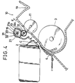
- Fig. 4 is a sectional side view of a modification of the ink jet printer of Fig. 1, in which a main case and a sheet feed unit are omitted;
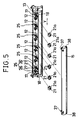
- Fig. 5 is a perspective view of a cleaning member holding unit included in an ink jet printer in an embodiment according to the present invention;
- Fig. 6 is a sectional side view of the cleaning member holding unit of Fig. 5 holding cleaning rollers;
- Fig. 7 is a fragmentary perspective view of the cleaning member holding unit of Fig. 5 holding the cleaning rollers;
- Fig. 8 is a front view of assistance in explaining the positional relation between the pinch roller and the corresponding cleaning roller of the ink jet printer of Fig. 5; and
- Fig. 9 is a sectional side view of a known ink jet printer relevant to the present invention.
-
- Referring to Figs. 1 to 3, an ink jet printer in an example useful in understanding the present invention comprises a
feed roller 3, an inkjet print head 2, and asheet ejecting mechanism 10 comprising anejecting roller 11 andpinch rollers 12, which are arranged sequentially along a sheet feed passage 1. The sheet feed passage 1 is defined by a sheet guide panel 9 having a substantially U-shaped cross section and associated parts so as to extend from a sheet feed unit A via a printing unit C to a sheet ejecting unit B. The sheet feed unit A has a sheet feed tray, not shown, the inkjet print head 2 is included in the printing unit C, and the sheet ejecting unit B has adelivery tray 19. Thefeed roller 3 is disposed at a position corresponding to a substantially U-shaped bend formed in the sheet feed passage 1. The feed roller is driven for rotation by a driving unit, not shown, to feed recording sheets stacked in layers on the sheet feed tray sequentially one at a time into the sheet feed passage 1 and feeds the recording sheet to the printing unit C in cooperation with aleaf plate 4. The inkjet print head 2 is mounted on a carriage, not shown, capable of traveling in directions perpendicular to the paper as viewed in Fig. 1 to print desired characters and the like on the recording sheet by jetting ink droplets against the recording sheet. Thesheet ejecting mechanism 10 is disposed immediately before the sheet delivery tray 19 on the sheet feed passage 1. The ejectingroller 11 of thesheet ejecting mechanism 10 is partially protruded through openings 20 formed in the sheet guide panel 9 into the sheet feed passage 1. - The
pinch rollers 12 are disposed so as to be in contact with the printed surface of the printed recording sheet on which characters and the like have been printed by the printing unit C to press the printed recording sheet against the ejectingroller 11 so that the printed recording sheet is advanced in an ejecting direction, i.e., the direction of the arrow in Fig. 1, by the synergetic actions of the ejectingroller 11 and thepinch rollers 12. In this embodiment, the number of thepinch rollers 12 is six. The pinch rollers are supported for rotation on asupport shaft 12a held on theroller holder 13. -
Cleaning rollers 21, namely, cleaning members, formed of a material capable of efficiently absorbing the ink are supported for rotation on asupport shaft 21a. Thesupport shaft 21a is held on aroller holder 13 so that the cleaningrollers 21 are disposed above the printing unit C and in contact with the respective circumferences of thepinch rollers 12, respectively. In this embodiment, the number of the cleaningrollers 21 is six. - Cleaning
roller holding structures 31 for detachably holding thesupport shaft 21a supporting the cleaningrollers 21 are formed respectively in the opposite side walls of theroller holder 13. When thesupport shaft 21a is held in the cleaningroller holding structures 31 on theroller holder 13, the cleaningrollers 21 are pressed against the respective circumferences of thepinch rollers 12, respectively, at a specified pressure. As shown in Fig. 2, each cleaningroller holding structure 31 has apositioning recess 32 and aprotrusion 33. When the opposite ends of thesupport shaft 21a are fitted in the positioning recesses 32, thesupport shaft 21a is positioned by the cooperative function of the positioning recesses 32 and theprotrusions 33 so that the cleaningrollers 21 are held in contact with the respective circumferences of thepinch rollers 12 at a specified pressure. The positioning recesses 32 are inclined at a specified angle to a horizontal plane so as to open upward. - The
feed roller 3 is rotated to pull out the recording sheets stacked on the sheet feed tray one at a time into the sheet feed passage 1 and to feed the recording sheet to the printing unit C. The inkjet print head 2 of the printing unit C prints desired characters and the like on the recording sheet. Subsequently, the ejectingroller 11 and thepinch rollers 12 cooperate to advance the printed recording sheet in an ejecting direction, i.e., in the direction of the arrow E (Fig. 1). Thus, the printed recording sheet is ejected into thedelivery tray 19 and stored on thedelivery tray 19 with the printed surface thereof facing up. - The cleaning
rollers 21 in contact with the respective circumferences of thepinch rollers 12 absorb the ink transferred from the printed recording sheet to thepinch rollers 12 and adhering to the respective circumferences of thepinch rollers 12 to clean thepinch rollers 12. - When the cleaning
rollers 21 are worn into nappy rollers and the cleaning function of the same is deteriorated, thesupport shaft 21a supporting the cleaningrollers 21 is pulled out from the positioning recesses 32 of theroller holder 13, and anothersupport shaft 21a supportingnew cleaning rollers 21 is forced into the bottoms of the positioning recesses 32, deforming theprotrusions 33, whereby thenew cleaning rollers 21 are positioned correctly respectively in contact with the respective circumferences of thepinch rollers 12 at the specified pressure. Thus, theworn cleaning rollers 21 can be easily replaced with thenew cleaning rollers 21 without requiring special skill. - The positioning recesses 32 serve as both means for positioning the
cleaning rollers 21 and means for holding the cleaningrollers 21 in place. The simple construction of thepositioning structures 31 each having thepositioning recess 32 and theprotrusion 33 simplifies the construction of the ink jet printer, reduces the number of component parts of the ink jet printer and enables the ink jet printer to be formed in a relatively small construction. Since the positioning recesses 32 open upward on a high level and the cleaningrollers 21 are disposed above the printing unit C, the cleaningrollers 21 can be easily put on and removed from theroller holder 13. - As shown in Fig. 4, a modification of the ink jet printer has a
roller holder 13 detachably provided with aprotective cover 15 for covering thecleaning rollers 21. Theprotective cover 15 covers the cleaningrollers 21 so that the hands and the like will not be stained with the ink absorbed by the cleaningrollers 21 when inspecting the internal components of the ink jet printer. Theprotective cover 15 may be transparent to enable the observation of the condition of the cleaningrollers 21. Theprotective cover 15 may be hinged on theroller holder 13 so that theprotective cover 15 can be moved away from the vicinity of the cleaningrollers 21 to enable thecleaning rollers 21 to be removed from theroller holder 13. - An ink jet printer in an embodiment according to the present invention will be described hereinafter with reference to Figs. 5 to 8, in which parts like or corresponding to those of the ink jet printer in the earlier example are denoted by the same reference characters and the description thereof will be omitted.
- The ink jet printer is provided with six pairs of
pinch rollers 12 and six pairs of cleaning rollers. Referring to Fig. 8, each pair ofpinch rollers 12 are mounted with a space therebetween on asupport shaft 12a, and each pair of cleaningrollers 21 are mounted contiguously on asupport shaft 21a. Each of the cleaningrollers 21 has a surface layer having a thickness t of 4 mm and formed of an urethane elastomer sponge ET (manufactured by BRIDGESTONE KASEIHIN K.K.). The surfaces of the cleaningrollers 21 are finished by grinding. - A
roller holder 13 is provided with six pairs of first support blocks 22, which are arranged longitudinally, i.e., along the direction of the arrow Y (Fig. 5), at predetermined intervals. Each pair ofpinch rollers 12 are supported for rotation in each pair of first support blocks 22 so as to be able to move away from an ejectingroller 11. The first support blocks 22 are provided respectively with taper recesses 23 for receiving thesupport shafts 12a supporting thepinch rollers 12. Therecesses 23 are inclined at an angle to a horizontal plane and have open ends opening upward, i.e., opening toward the left as viewed in Fig. 6. The inclination of therecesses 23 of the first support blocks 22 are determined so that thepinch rollers 12 are pressed against the ejectingroller 11 at a specified pressure by gravity and able to move smoothly away from the ejectingroller 11. In this embodiment, the inclination of therecesses 23 of the first support blocks 22 to a horizontal plane is 25°. As shown in Fig. 5, theroller holder 13 is provided in each of its opposite ends with arecess 17 and aprotrusion 18 for detachably joining aprotective cover 15 to theroller holder 13. - Referring to Figs. 5 and 7, the
roller holder 13 is provided with sixsupports 25 at positions respectively corresponding to the six pairs of first support blocks 22. Eachsupport 25 has a pair of second support blocks 26. The second support blocks 26 are provided respectively withrecesses 27 to support thesupport shafts 21a each supporting each pair of cleaningrollers 21 for rotation and for free movement in one direction. As shown in Fig. 6, therecesses 27 of the second support blocks 26 are inclined to a horizontal plane and have open ends opening upward, i.e., opening toward the left as viewed in Fig. 6. The inclination of therecesses 27 of the second support blocks 26 is determined so that the cleaningrollers 21 are able to move smoothly according to the movement of thepinch rollers 12. In this embodiment, the inclination to a horizontal plane is 25°. - The
protective cover 15 is joined detachably to theroller holder 13 so as to cover thecleaning rollers 21. Theprotective cover 15 is provided withhooks 37 and holes 38 corresponding to therecesses 17 and theprotrusions 18, respectively of theroller holder 13. When joining theprotective cover 15 to theroller holder 13, theprotrusions 18 of theroller holder 13 are fitted in the holes of theprotective cover 15, and thehooks 37 of theprotective cover 15 are brought into engagement with therecesses 17 of theroller holder 13, respectively. - As shown in Fig. 6, the
protective cover 15 is provided with a pair ofribs 32 to retain thesupport shafts 21a supporting the cleaningrollers 21 within therecesses 27 of thesupports 25 to prevent thecleaning rollers 21 coming into contact with the inner surface of theprotective cover 15 and becoming unable to rotate. - Thus, the
support shafts 21a of supporting the cleaningrollers 21 are supported for rotation in thesupports 25 of theroller holder 13 and the cleaningrollers 21 are kept in contact respectively with thepinch rollers 12 by gravity. Therefore, even if theroller holder 13 is deformed in a longitudinally curved shape, i.e., a curved shape with respect to the direction of the arrow Y (Fig. 5), due to incorrect manufacture, theindividual cleaning rollers 21 are able to adapt themselves to the deformation of theroller holder 13 and to be in correct contact with thecorresponding pinch rollers 12. Thus, the ink adhering to thepinch rollers 12 can be completely removed. - When a thick printed recording sheet P, such as an envelope is inserted between the
pinch rollers 12 and the ejectingroller 11, thepinch rollers 12 are moved away from the ejectingroller 11 by the thick printed recording sheet P, and the cleaningrollers 21 move toward the open ends of therecesses 27 according to the movement of thepinch rollers 12. Thus, the movement of thepinch rollers 12 away from the ejectingroller 11 is not obstructed by the cleaningrollers 21, so that the printed recording sheet P can be smoothly advanced in the ejecting direction, i.e., the direction of the arrow E (Fig. 4). The inclination of therecesses 27 receiving thesupport shafts 21a supporting the cleaningrollers 21 is determined so as to secure the smooth movement of the cleaningrollers 21 according to the movement of thecorresponding pinch rollers 12. Accordingly, the cleaningrollers 21 can be moved toward the open ends of therecesses 27 by force far lower than that necessary for vertically lifting up the cleaningrollers 21, so that the recording sheet P can be smoothly ejected. - Although this embodiment employs the six pairs of
pinch rollers 12 to press the recording sheet P at twelve points to press the recording sheet P against the ejectingrollers 11 so that the recording sheet P will not separate from the ejectingroller 11, the ink jet printer may be provided with six pinch rollers.
Claims (2)
- An ink jet printer capable of printing desired characters and the like on a recording sheet by jetting ink droplets against the recording sheet, said ink jet printer comprising:sheet guide members forming a sheet feed passage (1) extending between a sheet feed unit (A) and a sheet ejecting unit (B);an ink jet print head (2) for printing characters and the like on a recording sheet travelling along the sheet feed passage;an ejecting roller (11) disposed so as to be in contact with the non-printed surface of a printed recording sheet to eject the printed recording sheet into the ejecting unit;a plurality of individual saw-toothed pinch rollers (12) disposed so as to be in contact with the printed surface of the printed recording sheet to press the printed recording sheet against the ejecting roller (11);a plurality of individual cleaning members (21) disposed in contact respectively with the respective circumferences of the pinch rollers to remove the ink adhering to the circumferences of the pinch rollers; anda holding member (13) arranged to hold the cleaning members in contact respectively with the pinch rollers wherein the holding member (13) is arranged to carry support shafts (12a) for the pinch rollers, said shafts (12a) being located within recesses (23) which are inclined to the horizontal to enable the pinch rollers (12) to move towards and away from the eject roller under pressure due to gravity,and that the holding member (13) also carries support shafts (21a) for the cleaning members (21), said support shafts (21a) being located within recesses (27) which are also inclined to the horizontal so enabling the cleaning members to move in accordance with the movement of the pinch rollers (12).
- An ink jet printer according to Claim 1 further comprising a protective cover (15) joined to said holding member (13) so as to be moveable between a closed position for covering said cleaning members (21) and an open position for allowing access to said cleaning members (21) when removing said cleaning members from said holding member, and provided with ribs (32) formed so as to be disposed contiguously with the open ends of the recesses (27) to retain the support shafts (21a) supporting said cleaning members within the recesses.
Applications Claiming Priority (6)
| Application Number | Priority Date | Filing Date | Title |
|---|---|---|---|
| JP19206792 | 1992-07-20 | ||
| JP4192067A JPH0631908A (en) | 1992-07-20 | 1992-07-20 | Inkjet printer |
| JP192067/92 | 1992-07-20 | ||
| JP33862792A JP2738627B2 (en) | 1992-12-18 | 1992-12-18 | Inkjet printer |
| JP33862792 | 1992-12-18 | ||
| JP338627/92 | 1992-12-18 |
Publications (3)
| Publication Number | Publication Date |
|---|---|
| EP0580401A2 EP0580401A2 (en) | 1994-01-26 |
| EP0580401A3 EP0580401A3 (en) | 1995-01-25 |
| EP0580401B1 true EP0580401B1 (en) | 2000-01-26 |
Family
ID=26507084
Family Applications (1)
| Application Number | Title | Priority Date | Filing Date |
|---|---|---|---|
| EP93305690A Expired - Lifetime EP0580401B1 (en) | 1992-07-20 | 1993-07-20 | Ink jet printer |
Country Status (4)
| Country | Link |
|---|---|
| US (1) | US5719611A (en) |
| EP (1) | EP0580401B1 (en) |
| KR (1) | KR0147859B1 (en) |
| DE (1) | DE69327685T2 (en) |
Families Citing this family (6)
| Publication number | Priority date | Publication date | Assignee | Title |
|---|---|---|---|---|
| JP3126612B2 (en) * | 1994-12-26 | 2001-01-22 | キヤノン株式会社 | Recording medium transport device |
| JP2899234B2 (en) * | 1995-07-27 | 1999-06-02 | キヤノン株式会社 | Recording device |
| JP2001058734A (en) * | 1999-06-09 | 2001-03-06 | Tohoku Ricoh Co Ltd | Printing device |
| US7434928B2 (en) * | 2004-09-17 | 2008-10-14 | Ricoh Company, Ltd. | Image forming apparatus |
| JP5609262B2 (en) | 2010-05-26 | 2014-10-22 | セイコーエプソン株式会社 | Transport roller cleaning mechanism and printer |
| US8931970B1 (en) * | 2012-02-08 | 2015-01-13 | Pyramid Group, Inc. | Ticket printer |
Family Cites Families (6)
| Publication number | Priority date | Publication date | Assignee | Title |
|---|---|---|---|---|
| US5291224A (en) * | 1989-10-27 | 1994-03-01 | Canon Kabushiki Kaisha | Sheet feeding apparatus using pairs of spur rollers |
| JPH04126253A (en) * | 1990-09-18 | 1992-04-27 | Fuji Electric Co Ltd | Ink jet printer |
| EP0571220B1 (en) * | 1992-05-22 | 1996-10-16 | Kabushiki Kaisha TEC | Exchangeable assembly of inkjet printer head and ink cartridge |
| KR970000610B1 (en) * | 1992-06-04 | 1997-01-16 | 가부시키가이샤 테크 | Paper ejecting device of printer |
| JPH0632023A (en) * | 1992-07-20 | 1994-02-08 | Tokyo Electric Co Ltd | Inkjet printer |
| KR970003653B1 (en) * | 1992-07-22 | 1997-03-20 | 가부시키가이샤 테크 | Paper feeding apparatus for a printer |
-
1993
- 1993-07-15 KR KR1019930013317A patent/KR0147859B1/en not_active Expired - Fee Related
- 1993-07-20 DE DE69327685T patent/DE69327685T2/en not_active Expired - Lifetime
- 1993-07-20 EP EP93305690A patent/EP0580401B1/en not_active Expired - Lifetime
-
1995
- 1995-05-10 US US08/438,365 patent/US5719611A/en not_active Expired - Lifetime
Also Published As
| Publication number | Publication date |
|---|---|
| DE69327685T2 (en) | 2000-07-27 |
| KR940002059A (en) | 1994-02-16 |
| US5719611A (en) | 1998-02-17 |
| DE69327685D1 (en) | 2000-03-02 |
| EP0580401A3 (en) | 1995-01-25 |
| KR0147859B1 (en) | 1998-08-17 |
| EP0580401A2 (en) | 1994-01-26 |
Similar Documents
| Publication | Publication Date | Title |
|---|---|---|
| EP1043166B1 (en) | Ink-jet recording apparatus | |
| EP0914959B1 (en) | Printer cutter device | |
| EP1046509A1 (en) | Media handling in an inkjet printer | |
| JPH0375038B2 (en) | ||
| GB2287433A (en) | Paper guiding and feeding and ink collection in an ink jet printer | |
| US5719611A (en) | Ink jet printer with holding member for easily replacing cleaning member | |
| JP2021130286A (en) | Printing equipment | |
| EP0368685B1 (en) | Sheet-feed/sheet-receiving unit used in combination with printer | |
| EP1782956B1 (en) | Ink-jet recording apparatus | |
| US5599120A (en) | Adapter for ink jet printing onto adhesive binding tape | |
| US7645037B2 (en) | Printer structure | |
| JP2010179387A (en) | Cutting device and image recording apparatus having the same | |
| KR100732188B1 (en) | Printing device for easy paper jam handling and mini printer with same | |
| JPH0552275B2 (en) | ||
| JPH0286475A (en) | liquid jet recording device | |
| GB2290262A (en) | Paper handling in ink jet printer. | |
| JPS63251267A (en) | printer | |
| JPH05177827A (en) | Inkjet printer | |
| US11607895B2 (en) | Printing apparatus including a detachable star wheel | |
| JP2002254737A (en) | Printer | |
| JP2021003864A (en) | Printer | |
| JP2738628B2 (en) | Inkjet printer | |
| JP2738627B2 (en) | Inkjet printer | |
| JPH02293154A (en) | liquid jet recording device | |
| JPH072385A (en) | Paper sheet conveying device |
Legal Events
| Date | Code | Title | Description |
|---|---|---|---|
| PUAI | Public reference made under article 153(3) epc to a published international application that has entered the european phase |
Free format text: ORIGINAL CODE: 0009012 |
|
| 17P | Request for examination filed |
Effective date: 19930729 |
|
| AK | Designated contracting states |
Kind code of ref document: A2 Designated state(s): DE FR GB |
|
| PUAL | Search report despatched |
Free format text: ORIGINAL CODE: 0009013 |
|
| AK | Designated contracting states |
Kind code of ref document: A3 Designated state(s): DE FR GB |
|
| RAP1 | Party data changed (applicant data changed or rights of an application transferred) |
Owner name: KABUSHIKI KAISHA TEC |
|
| 17Q | First examination report despatched |
Effective date: 19960118 |
|
| GRAG | Despatch of communication of intention to grant |
Free format text: ORIGINAL CODE: EPIDOS AGRA |
|
| GRAG | Despatch of communication of intention to grant |
Free format text: ORIGINAL CODE: EPIDOS AGRA |
|
| RAP1 | Party data changed (applicant data changed or rights of an application transferred) |
Owner name: TOSHIBA TEC KABUSHIKI KAISHA |
|
| GRAG | Despatch of communication of intention to grant |
Free format text: ORIGINAL CODE: EPIDOS AGRA |
|
| GRAH | Despatch of communication of intention to grant a patent |
Free format text: ORIGINAL CODE: EPIDOS IGRA |
|
| GRAH | Despatch of communication of intention to grant a patent |
Free format text: ORIGINAL CODE: EPIDOS IGRA |
|
| GRAA | (expected) grant |
Free format text: ORIGINAL CODE: 0009210 |
|
| AK | Designated contracting states |
Kind code of ref document: B1 Designated state(s): DE FR GB |
|
| PG25 | Lapsed in a contracting state [announced via postgrant information from national office to epo] |
Ref country code: FR Free format text: LAPSE BECAUSE OF FAILURE TO SUBMIT A TRANSLATION OF THE DESCRIPTION OR TO PAY THE FEE WITHIN THE PRESCRIBED TIME-LIMIT Effective date: 20000126 |
|
| REF | Corresponds to: |
Ref document number: 69327685 Country of ref document: DE Date of ref document: 20000302 |
|
| EN | Fr: translation not filed | ||
| PG25 | Lapsed in a contracting state [announced via postgrant information from national office to epo] |
Ref country code: GB Free format text: LAPSE BECAUSE OF NON-PAYMENT OF DUE FEES Effective date: 20000720 |
|
| PLBE | No opposition filed within time limit |
Free format text: ORIGINAL CODE: 0009261 |
|
| STAA | Information on the status of an ep patent application or granted ep patent |
Free format text: STATUS: NO OPPOSITION FILED WITHIN TIME LIMIT |
|
| 26N | No opposition filed | ||
| GBPC | Gb: european patent ceased through non-payment of renewal fee |
Effective date: 20000720 |
|
| PGFP | Annual fee paid to national office [announced via postgrant information from national office to epo] |
Ref country code: DE Payment date: 20120718 Year of fee payment: 20 |
|
| REG | Reference to a national code |
Ref country code: DE Ref legal event code: R071 Ref document number: 69327685 Country of ref document: DE |
|
| PG25 | Lapsed in a contracting state [announced via postgrant information from national office to epo] |
Ref country code: DE Free format text: LAPSE BECAUSE OF EXPIRATION OF PROTECTION Effective date: 20130723 |