EP0580049A1 - Piezo-electric motor - Google Patents
Piezo-electric motor Download PDFInfo
- Publication number
- EP0580049A1 EP0580049A1 EP93111102A EP93111102A EP0580049A1 EP 0580049 A1 EP0580049 A1 EP 0580049A1 EP 93111102 A EP93111102 A EP 93111102A EP 93111102 A EP93111102 A EP 93111102A EP 0580049 A1 EP0580049 A1 EP 0580049A1
- Authority
- EP
- European Patent Office
- Prior art keywords
- rotor
- stator
- support
- piezoelectric
- piezoelectric motor
- Prior art date
- Legal status (The legal status is an assumption and is not a legal conclusion. Google has not performed a legal analysis and makes no representation as to the accuracy of the status listed.)
- Granted
Links
- 230000033001 locomotion Effects 0.000 claims abstract description 27
- 230000005540 biological transmission Effects 0.000 claims abstract description 12
- 238000005452 bending Methods 0.000 claims description 20
- 230000002093 peripheral effect Effects 0.000 claims description 6
- 239000000463 material Substances 0.000 claims description 5
- 239000000919 ceramic Substances 0.000 description 6
- 238000006073 displacement reaction Methods 0.000 description 6
- 208000031968 Cadaver Diseases 0.000 description 4
- 240000008042 Zea mays Species 0.000 description 4
- 230000001133 acceleration Effects 0.000 description 3
- 229910001369 Brass Inorganic materials 0.000 description 2
- PXHVJJICTQNCMI-UHFFFAOYSA-N Nickel Chemical compound [Ni] PXHVJJICTQNCMI-UHFFFAOYSA-N 0.000 description 2
- 229910045601 alloy Inorganic materials 0.000 description 2
- 239000000956 alloy Substances 0.000 description 2
- 239000010951 brass Substances 0.000 description 2
- 230000005284 excitation Effects 0.000 description 2
- 230000007246 mechanism Effects 0.000 description 2
- 239000007769 metal material Substances 0.000 description 2
- 239000010935 stainless steel Substances 0.000 description 2
- 229910001220 stainless steel Inorganic materials 0.000 description 2
- 229910001256 stainless steel alloy Inorganic materials 0.000 description 2
- 239000004575 stone Substances 0.000 description 2
- VYZAMTAEIAYCRO-UHFFFAOYSA-N Chromium Chemical compound [Cr] VYZAMTAEIAYCRO-UHFFFAOYSA-N 0.000 description 1
- 229920000297 Rayon Polymers 0.000 description 1
- NRTOMJZYCJJWKI-UHFFFAOYSA-N Titanium nitride Chemical compound [Ti]#N NRTOMJZYCJJWKI-UHFFFAOYSA-N 0.000 description 1
- QCWXUUIWCKQGHC-UHFFFAOYSA-N Zirconium Chemical compound [Zr] QCWXUUIWCKQGHC-UHFFFAOYSA-N 0.000 description 1
- 230000009471 action Effects 0.000 description 1
- 229910052782 aluminium Inorganic materials 0.000 description 1
- XAGFODPZIPBFFR-UHFFFAOYSA-N aluminium Chemical compound [Al] XAGFODPZIPBFFR-UHFFFAOYSA-N 0.000 description 1
- 238000012550 audit Methods 0.000 description 1
- DMFGNRRURHSENX-UHFFFAOYSA-N beryllium copper Chemical compound [Be].[Cu] DMFGNRRURHSENX-UHFFFAOYSA-N 0.000 description 1
- 210000004027 cell Anatomy 0.000 description 1
- 229910052804 chromium Inorganic materials 0.000 description 1
- 239000011651 chromium Substances 0.000 description 1
- 238000010276 construction Methods 0.000 description 1
- 230000008878 coupling Effects 0.000 description 1
- 238000010168 coupling process Methods 0.000 description 1
- 238000005859 coupling reaction Methods 0.000 description 1
- 238000010586 diagram Methods 0.000 description 1
- VJPLIHZPOJDHLB-UHFFFAOYSA-N lead titanium Chemical compound [Ti].[Pb] VJPLIHZPOJDHLB-UHFFFAOYSA-N 0.000 description 1
- 238000012423 maintenance Methods 0.000 description 1
- 229910052751 metal Inorganic materials 0.000 description 1
- 239000002184 metal Substances 0.000 description 1
- 229910052759 nickel Inorganic materials 0.000 description 1
- 230000000750 progressive effect Effects 0.000 description 1
- 239000002964 rayon Substances 0.000 description 1
- 230000004044 response Effects 0.000 description 1
- 229910052709 silver Inorganic materials 0.000 description 1
- 239000004332 silver Substances 0.000 description 1
- 239000007787 solid Substances 0.000 description 1
- 230000009466 transformation Effects 0.000 description 1
- 230000001131 transforming effect Effects 0.000 description 1
- 229910052726 zirconium Inorganic materials 0.000 description 1
Images


Classifications
-
- H—ELECTRICITY
- H02—GENERATION; CONVERSION OR DISTRIBUTION OF ELECTRIC POWER
- H02N—ELECTRIC MACHINES NOT OTHERWISE PROVIDED FOR
- H02N2/00—Electric machines in general using piezoelectric effect, electrostriction or magnetostriction
-
- H—ELECTRICITY
- H02—GENERATION; CONVERSION OR DISTRIBUTION OF ELECTRIC POWER
- H02N—ELECTRIC MACHINES NOT OTHERWISE PROVIDED FOR
- H02N2/00—Electric machines in general using piezoelectric effect, electrostriction or magnetostriction
- H02N2/10—Electric machines in general using piezoelectric effect, electrostriction or magnetostriction producing rotary motion, e.g. rotary motors
- H02N2/103—Electric machines in general using piezoelectric effect, electrostriction or magnetostriction producing rotary motion, e.g. rotary motors by pressing one or more vibrators against the rotor
-
- G—PHYSICS
- G04—HOROLOGY
- G04C—ELECTROMECHANICAL CLOCKS OR WATCHES
- G04C3/00—Electromechanical clocks or watches independent of other time-pieces and in which the movement is maintained by electric means
- G04C3/08—Electromechanical clocks or watches independent of other time-pieces and in which the movement is maintained by electric means wherein movement is regulated by a mechanical oscillator other than a pendulum or balance, e.g. by a tuning fork, e.g. electrostatically
- G04C3/12—Electromechanical clocks or watches independent of other time-pieces and in which the movement is maintained by electric means wherein movement is regulated by a mechanical oscillator other than a pendulum or balance, e.g. by a tuning fork, e.g. electrostatically driven by piezoelectric means; driven by magneto-strictive means
-
- H—ELECTRICITY
- H02—GENERATION; CONVERSION OR DISTRIBUTION OF ELECTRIC POWER
- H02N—ELECTRIC MACHINES NOT OTHERWISE PROVIDED FOR
- H02N2/00—Electric machines in general using piezoelectric effect, electrostriction or magnetostriction
- H02N2/0005—Electric machines in general using piezoelectric effect, electrostriction or magnetostriction producing non-specific motion; Details common to machines covered by H02N2/02 - H02N2/16
- H02N2/001—Driving devices, e.g. vibrators
- H02N2/0015—Driving devices, e.g. vibrators using only bending modes
-
- H—ELECTRICITY
- H02—GENERATION; CONVERSION OR DISTRIBUTION OF ELECTRIC POWER
- H02N—ELECTRIC MACHINES NOT OTHERWISE PROVIDED FOR
- H02N2/00—Electric machines in general using piezoelectric effect, electrostriction or magnetostriction
- H02N2/0005—Electric machines in general using piezoelectric effect, electrostriction or magnetostriction producing non-specific motion; Details common to machines covered by H02N2/02 - H02N2/16
- H02N2/005—Mechanical details, e.g. housings
- H02N2/0065—Friction interface
Definitions
- the present invention relates to a piezoelectric motor.
- the invention relates to a thin piezoelectric motor which can be fitted to a timepiece.
- FIG. 1 A small piezoelectric motor capable of satisfying such an application is described in patent application CH 02 553 / 91-0, filed on August 30, 1991 in the name of the applicant.
- This piezoelectric motor which is shown in Figures 1, 2 and 3 appended and which will be described in detail below, conventionally comprises, on the one hand, a stator associated with piezoelectric means, and on the other hand apart, a rotor which is rotatably mounted on this stator.
- the piezoelectric means consist of a polarized ceramic which can be electrically excited to involve a vibratory movement on the stator, while the rotor is provided with bending blades arranged in elastic support on the stator. These blades are shaped to ensure the transmission of this vibratory movement to the rotor.
- support means comprising a spring in the form of a cup.
- This spring is held axially by a head screw engaged in a stepped fixed axis which forms a support and which urges the rotor along this axis. Between the head of the screw and the spring is disposed a bearing allowing the concomitant rotation of the rotor-spring assembly.
- This motor has a space requirement in height such that it cannot be fitted to timepieces having by nature a small thickness.
- the present invention aims to overcome this drawback by providing a piezoelectric motor thin enough to equip a timepiece without affecting its dimensional characteristics.
- This motor which is identified by the general reference M1, comprises a support 2 which is, in this example, constituted by a base 4 in which is embedded, in particular by force fitting of the hunting type, a stepped pin or tenon 6 protruding .
- the pin 6 materializes a geometric axis X1, forming a geometric axis of rotation around which a rotor R1 can rotate.
- the base 4 and the post 6 are made of a metallic material, such as brass or an alloy of the stainless steel type.
- the base assembly 4 - stud 6 therefore constitutes a fixed structure forming the support of this piezoelectric motor.
- the motor M1 also includes a stator S1 which is fixedly mounted, likewise by force fitting (driving) or by bonding, on the post 6.
- piezoelectric means 10 consisting, on the one hand, of a piezoelectric element 10a, such as a ceramic which is polarized uniformly according to its thickness, and on the other hand, of two electrodes 10b and 10c which are conventionally connected to a power supply AL, shown here schematically.
- the piezoelectric means 10 therefore form a transducer which, in response to an electrical excitation supplied by the supply AL via the electrodes 10b and 10c can take on a vibratory movement.
- the stator S1 is constituted by a disc 12 having in its center a through hole 14 which, in this example, is fixedly held on the post 6.
- the disc 12 which forms the framework of the stator S1 rests in axial support on a shoulder 16 of this post.
- a face F1 of the disc 12 disposed facing the base 4 and called the rear face, is hollowed out in its central part to reveal a blind recess or recess 18, opening towards the base 4.
- This recess 18 defines on the rear face F1 of the disc 12, an annular collar 20 on which are fixedly mounted the piezoelectric means 10 which have the same annular shape.
- the rotor R1 As for the rotor R1, it rests axially on a face F2 of the disc 12, opposite the face F1, while it is freely engaged by a central orifice 32 on the post 6.
- the rotor R1 comprises a body which is formed, in this embodiment, by a disc D1 of thin thickness made of a material such as metal, ceramic or hard plastic.
- the disc D1 forms a rigid and load-bearing structure which can mesh with coupling means, not shown.
- the piezoelectric motor M1 further comprises motion transmission means 36 shaped to transmit to the rotor R1 the vibratory movement of the stator S1 and to move the rotor R1 in rotation around its axis X1, in a normal plane of movement Pdm to the axis of rotation X1.
- These transmission means 36 are formed by elastically deformable members constituted by blades of flexion 38.
- the flexion blades 38 are, in the example of FIG. 1, embedded in the disc D1 forming the support structure or body of the rotor R1.
- the rotor R1 is biased in the axial direction towards the stator S1 by means of support means 39.
- These means 39 which allow the axial support of the rotor R1 on the stator S1 here consist of a cup-shaped spring 42 mounted on the post 6 and biased in the axial direction by a bearing 44 which is itself disposed on the post 6 and which is held thereon by a head screw V1 mounted at the free end of said post.
- These support means allow the adjustment of the support pressure of the rotor R1 on the stator S1, by screwing or unscrewing the screw V1.
- FIGS 2 and 3 show a particular embodiment of the rotor described in the aforementioned Swiss application.
- the elastically deformable members 36 are constituted by curved bending blades 50 (of which only one is referenced) formed on a solid disc 52 with which the latter come in one piece.
- the disc 52 is attached under the disc D1 forming the body of the rotor R1 and it is fixedly integral with the latter.
- the flexure blades 50 are formed at the periphery of the disc 52 by a cold deformation operation, and in particular by stamping.
- the motor M2 comprises a rotor R2 which is rotatably mounted, around the geometric axis X1, on a stator S2 embedded in the base 4.
- the stator S2 comprises a support structure ensuring the support of the rotor R2, this structure essentially consisting of a suspended annular plate P2 fixedly held in the base 4.
- the plate P2 is formed, on the one hand, by a disc 60 elastically deformable under which the piezoelectric means 10 are subjected and which has a low uniform thickness, of the order of 0.1 mm (0.1.10 ⁇ 3 meter)
- the plate P2 further comprises a cylindrical tubular barrel 62 projecting from the disc 60 and coming integrally with it.
- the barrel 62 is therefore fixedly removed by force fitting or by bonding in an orifice, not referenced, of the base 4.
- the barrel 62 has a central orifice opening 64 into which is driven a smooth cylindrical tenon with a head V2 which ensures the axial maintenance and the guiding in rotation of the rotor R2 around the axis X1, thanks to two coaxial bearing surfaces (not referenced) formed on this one.
- the rotor R2 comprises a stepped tubular hub 66 of rigid structure, mounted for rotation about the axis X1, on the stud V2.
- the hub 66 comprises mechanical drive means formed, for example, by an external toothing 67 formed at the periphery thereof.
- the toothing 67 is intended to mesh with a drive mechanism, not shown.
- the hub 66 furthermore comprises, under its toothing 67 (taking the motor M2 in its position shown in FIG. 4) a shouldered seat 68 on which the body of the rotor R2 is fixedly engaged.
- the rotor body R2 is, according to the invention, essentially constituted by a perforated flexible disc D2.
- the disc D2 has an annular central part 70 (FIG. 6) which has a central opening 72 and which is connected, by this opening, to the hub 66 while being fixedly engaged on the carried shoulder 68.
- the disc D2 also includes a peripheral ring 72 on which the flexure blades 50 are formed.
- the disc D2 comprises bending arms 74 (for example here four in number, only one being referenced) which resiliently connect the central part 70 and the peripheral ring 72.
- the transmission means 36 which are formed by the bending blades 50 extending from the peripheral ring 72 towards the stator S2, the bending arms 74, the central part 70, as well as the ring 72 are made of material and form a monolithic rotor part.
- the peripheral ring 72, the bending arms 74 and the central part 70 have the same thickness and are, in the rest state (FIGS. 7 and 9), arranged in the same plane (not referenced).
- the body of the rotor R2 is formed by a structure which is elastically deformable, at least in the direction of the stator S2, and which at least partly forms the elastic support means of the rotor R2 on the stator S2, these means being referenced 79.
- These means are also formed in part by the hub 66 which biases the disk D2 axially towards the stator in an axisymmetric manner (relative to the axis X1), while being held by the head, not referenced, of the embedded stud V2.
- the body of the rotor R2 is formed essentially by the elastically disc deformable D2 which forms in an integrated manner said transmission means 36 and said elastic support means 79.
- the hub 66 permanently deforms, under the action of the pin V2, the body of the rotor R2 which is prestressed and which takes the form of bowl.
- the electrodes 10b and 10c of the piezoelectric means 10 both in front projection a full and entire structure, that is to say not cut and not structured by polarized segments, as is the case in classical structures.
- the disc D2 forming the stator S2 is preferably made of a metallic material, such as brass, a stainless steel alloy or aluminum, possibly coated with a thin layer of a hard material, especially chromium or titanium nitride.
- the electrodes 10b and 10c are preferably made of nickel or silver.
- the flexure blades 50 therefore project from the rotor R2, and in particular from the disk D2, in the direction of the front face of the stator S2 at an angle of inclination ⁇ originating from a straight line parallel to the axis of rotation X1.
- the angle ⁇ is between 10 and 30 °.
- each bending blade 50 which has a planar shape of the parallelepiped type protrudes from the rotor R2 over a free length Lcs preferably chosen in values between 0.1 and 0.5 mm (0.1 and 0, 5.10 ⁇ 3 meters).
- each blade 50 has a thickness ec having a value between 0.025 and 0.1 mm (0.025 and 0.1.10 ⁇ 3 meters) and a width lc having a value lying between 0.1 and 0.3 mm (0 , 1 and 0.3.10 ⁇ 3 meters).
- the flexure blades 50 are made of a material, such as an alloy of the beryllium-copper type or of the stainless steel type.
- stator S2 has a bending deformation on either side of its rest position identified by the reference A1. This deformation is very exaggerated by the extreme high and low positions B and C, and in reality it does not exceed a beat amplitude greater than 5 ⁇ m (5.10 ⁇ 6 meters), at the periphery of the stator (arrow). This deformation gives the stator S2 a bowl shape. This deformation in the bowl is due to bending stresses generated in the stator S2 thanks to the piezoelectric means 10. These bending stresses are due to the heterogeneous bimorph structure formed by the rigid assembly of the piezoelectric means 10 on the stator S2.
- a particular ceramic which is adapted to deform radially when a specific electrical excitation, via the electrodes, is applied to it. More particularly, a ceramic is chosen having a piezoelectric constant d, high, this constant representing the deformation obtained with respect to the applied field.
- this vibratory movement and this axisymmetric deformation are centered on the axis of rotation X1.
- a stepped planar motor that is to say having a stator and a rotor of essentially planar shape and superimposed, motor which thanks to the axisymmetric movement centered on the axis of rotation and oriented according to it, is of the essentially axial vibratory movement type, with reference to the axis X1.
- each point for example Pt1 to Pt3 (figure 9) of the stator S2 performs at least in projection on the axis X1, an essentially linear displacement, in a parallel direction to the axis of rotation X1, of the same amplitude for each circle registered rotor at a given radius (for example Rb1 to Rbn) and in phase.
- the axisymmetric vibration mode of the piezoelectric motor according to the invention provides speed components T (only three, T1 to T3, being represented in FIG. 9) essentially normal to the plane of movement Pdm of the rotor R2.
- the stator S2 therefore has no significant speed component in the displacement plane Pdm in view of the extremely low vibration amplitudes. It therefore has no significant radial, centrifugal or centripetal acceleration. It is also remarkable to note that this stator does not present any tangential acceleration, acceleration which one finds on the opposite in the stators of the classic piezoelectric motors having a vibratory mode with progressive waves or stationary.
- FIG. 13 represents the deformation of the stator S2 when it is subjected to a second variant of the axisymmetric vibratory movement according to the invention, the reference D representing its rest position, while the references E and F represent the shape of the stator in its extreme positions of deformation when excited.
- This movement this time has a nodal circle, identified in particular at the radius Rb3 ( Figures 14 and 15). It is in fact noted that the curves C1 and C2 in FIG. 14 pass through an amplitude of zero value marking a vibration node in the stator.
- the disc 60 is in this case made of a stainless steel alloy, while the piezoelectric element 10a is made of a piezoelectric ceramic PZT type (Zirconium doped lead titanium).
- the vibration mode of the motor according to the invention can be generalized to a notation of the type B xo ; where x can vary from 0 to a number n.
- the piezoelectric means 10 are excited by the electrical supply AL, which makes them vibrate.
- the radial component of the vibration of the piezoelectric means 10 generates a bending vibration of the disc 60 by the principle of the heterogeneous bimorph, known to those skilled in the art.
- the power supply AL delivers an alternating signal of frequency F corresponding to the resonance frequency of the mode B X0 desired.
- stator S2 in its entirety is thus excited in resonance in mode B X0 corresponding to an axisymmetric vibratory movement as described above.
- the elastically deformable members 36 formed by the bending blades 50 therefore form movement transformation means capable of transmitting, and at the same time transforming, the essentially axial linear (or normal) movement of the stator, into a perpendicular rotary movement of the rotor. .
- the motor M3 comprises a stator S3 which is provided with the piezoelectric element 10 and the annular disc 60, described above. On this stator S3 is mounted a rotor R3 whose body which is identical to the rotor R2, comprises a perforated flexible disc D3 of the same structure as the disc D2.
- the rotor R3 differs in that it comprises a stepped hub 80 driven on a drive axis 82 passing through the stator S3, through a barrel 84 made in one piece with the disc 60 of the suspended plate P3.
- the hub 80 only supports the perforated flexible disk D3 to keep it stressed, as shown in FIG. 8, under elastic stress, towards the plate P3 of the rotor R3.
- the drive shaft 82 is mounted by a first guide means 86 formed by a pivot (same reference) rotatably mounted in a bearing 88 formed, in this example, by a driven stone in a second support 89 formed by a plate or by a bridge of a clockwork movement, shown here partially.
- This axis 82 is supported in rotation by a second guide means 90 constituted by a cylindrical bearing (same reference) formed on the axis 82, and mounted for rotation in a bearing 92 likewise formed by a stone which is driven into a recess , not referenced, formed in the barrel 84. It will be noted that the barrel 84 is itself driven into a plate or a bridge 94 which forms the support 2 of the stator S3.
- the drive axis 82 which is integral in rotation with the body of the rotor R3, via the hub 80, to ensure its guidance around the axis X1, is mounted for rotation at least inside the support 2 which it passes through to project outwardly therefrom and to cooperate with a mechanical engagement means 96 .
- This mechanical meshing means 96 is constituted, for example, by an externally toothed pinion shaped to come to mesh with a mechanism to be driven, not shown.
- the stator S3 has, by way of example, the same vibration modes as those previously described, the motors M3 and M2 having, for example, the same dimensions.
Abstract
Description
La présente invention concerne un moteur piézo-électrique.The present invention relates to a piezoelectric motor.
Plus particulièrement, l'invention concerne un moteur piézo-électrique de faible épaisseur, pouvant équiper une pièce d'horlogerie.More particularly, the invention relates to a thin piezoelectric motor which can be fitted to a timepiece.
Un moteur piézo-électrique de faible dimension pouvant satisfaire une telle application est décrit dans la demande de brevet CH 02 553/91-0, déposée le 30 Août 1991 au nom de la demanderesse. Ce moteur piézo-électrique, qui est représenté aux figures 1, 2 et 3 annexées et qui sera décrit de façon détaillée ci-après, comprend classiquement, d'une part, un stator associé à des moyens piézo-électriques, et d'autre part, un rotor qui est monté à rotation sur ce stator. Les moyens piézo-électriques sont constitués par une céramique polarisée qui peut être électriquement excitée pour impliquer un mouvement vibratoire au stator, tandis que le rotor est pourvu de lames de flexion disposées en appui élastique sur le stator. Ces lames sont conformées pour assurer la transmission de ce mouvement vibratoire au rotor.A small piezoelectric motor capable of satisfying such an application is described in
L'appui élastique du rotor sur le stator, via ces lames de transmission, est assuré par des moyens d'appui comportant un ressort en forme de cuvette. Ce ressort est maintenu axialement par une vis à tête engagée dans un axe fixe étagé qui forme support et qui sollicite le rotor, selon cet axe. Entre la tête de la vis et le ressort est disposé un roulement permettant la rotation concomitante de l'ensemble rotor-ressort.The elastic support of the rotor on the stator, via these transmission blades, is ensured by support means comprising a spring in the form of a cup. This spring is held axially by a head screw engaged in a stepped fixed axis which forms a support and which urges the rotor along this axis. Between the head of the screw and the spring is disposed a bearing allowing the concomitant rotation of the rotor-spring assembly.
Ce moteur présente un encombrement en hauteur tel qu'il ne peut équiper des pièces d'horlogerie présentant par nature une épaisseur faible.This motor has a space requirement in height such that it cannot be fitted to timepieces having by nature a small thickness.
Ainsi, la présente invention a-t-elle pour but de pallier cet inconvénient en fournissant un moteur piézo-électrique de faible épaisseur capable d'équiper une pièce d'horlogerie sans nuire à ses caractéristiques dimensionnelles.Thus, the present invention aims to overcome this drawback by providing a piezoelectric motor thin enough to equip a timepiece without affecting its dimensional characteristics.
A cet effet, la présente invention a pour objet un moteur piézo-électrique, du type comprenant :
- un support,
- un stator solidaire du support,
- des moyens piézo-électriques susceptibles d'être électriquement excités pour impliquer un mouvement vibratoire au stator,
- un rotor monté à rotation par rapport au support, ce rotor comportant un corps sur lequel sont disposés des moyens de transmission conformés pour transmettre le mouvement vibratoire du stator audit rotor et pour entraîner ce rotor en rotation, et
- des moyens d'appui élastique du rotor sur le stator,
- a support,
- a stator secured to the support,
- piezoelectric means capable of being electrically excited to involve a vibratory movement on the stator,
- a rotor mounted for rotation relative to the support, this rotor comprising a body on which are arranged transmission means designed to transmit the vibratory movement of the stator to said rotor and to drive this rotor in rotation, and
- elastic support means for the rotor on the stator,
Mais d'autres caractéristiques et avantages de l'invention apparaîtront à la lecture de la description détaillée qui suit, faite en référence aux dessins annexés qui sont donnés uniquement à titre d'exemple et dans lesquels:
- La figure 1 est une vue en coupe longitudinale d'un moteur piézo-électrique classique, tel que celui décrit dans la demande de
brevet CH 02 553/91-0, - la figure 2 est une vue faite selon la flèche II de la figure 3, représentant, en vue de dessous, un mode de réalisation particulier d'un élément rotorique du moteur décrit dans la demande suisse susmentionnée,
- la figure 3 est une vue de côté faite selon la flèche III de la figure 2, mais représentant l'élément de cette figure associé à un disque rigide pour former un rotor classique destiné à équiper le moteur de la figure 1,
- la figure 4 est une vue en coupe longitudinale, représentant un moteur selon un premier mode de réalisation de l'invention,
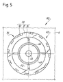
- la figure 5 est une vue de dessus du moteur de la figure 4,
- la figure 6 est une vue faite selon la flèche VI des figures 4 et 7, représentant uniquement le corps et les lames de transmission du rotor équipant le moteur selon l'invention,
- la figure 7 est une vue faite selon la flèche VII de la figure 6 et représentant de côté et dans une position de repos l'ensemble corps-lame de la figure 6,
- la figure 8 est une vue en coupe longitudinale, représentant un moteur selon un deuxième mode de réalisation de l'invention,
- la figure 9 est une vue de côté uniquement du rotor et du stator de la figure 4, mais représentés à une échelle différente pour une meilleure compréhension des dessins,
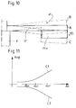
- la figure 10 est une demi-vue en section du stator des figures 4 et 8, représenté en traits plein dans sa position de repos, et en traits mixtes interrompus dans ses deux positions extrêmes de déformation lorsque ce stator est excité en vibration, selon une première variante du mouvement vibratoire selon l'invention,
- les figures 11 et 12 sont des diagrammes représentant les courbes de variation d'amplitude de la déformation du stator selon l'invention en fonction, respectivement, du rayon sur le stator et d'une position angulaire sur celui-ci,
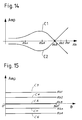
- la figure 13 est une demi-vue en section, similaire à la figure 10, mais représentant une deuxième variante du mouvement vibratoire selon l'invention, et
- les figures 14 et 15 sont respectivement des vues similaires à celles des figures 11 et 12, mais représentant des courbes de variation d'amplitude du stator lorsqu' il est mis en vibration selon la variante du mode vibratoire de la figure 13.
- FIG. 1 is a view in longitudinal section of a conventional piezoelectric motor, such as that described in
patent application CH 02 553 / 91-0, - FIG. 2 is a view taken along arrow II of FIG. 3, showing, in view from below, a particular embodiment of a rotor element of the motor described in the aforementioned Swiss application,
- Figure 3 is a side view taken along arrow III of Figure 2, but showing the element of this figure associated with a rigid disc to form a conventional rotor intended to equip the motor of FIG. 1,
- FIG. 4 is a view in longitudinal section, representing an engine according to a first embodiment of the invention,
- FIG. 5 is a top view of the engine of FIG. 4,
- FIG. 6 is a view taken along arrow VI of FIGS. 4 and 7, showing only the body and the transmission blades of the rotor equipping the engine according to the invention,
- FIG. 7 is a view taken along arrow VII of FIG. 6 and showing from the side and in a rest position the body-blade assembly of FIG. 6,
- FIG. 8 is a view in longitudinal section, representing an engine according to a second embodiment of the invention,
- FIG. 9 is a side view only of the rotor and the stator of FIG. 4, but shown on a different scale for a better understanding of the drawings,
- Figure 10 is a half-sectional view of the stator of Figures 4 and 8, shown in solid lines in its rest position, and in broken lines in its two extreme deformation positions when the stator is excited in vibration, according to a first variant of the vibratory movement according to the invention,
- FIGS. 11 and 12 are diagrams representing the amplitude variation curves of the deformation of the stator according to the invention as a function, respectively, of the radius on the stator and of an angular position thereon,
- FIG. 13 is a half-view in section, similar to FIG. 10, but showing a second variant of the vibratory movement according to the invention, and
- FIGS. 14 and 15 are respectively views similar to those of FIGS. 11 and 12, but showing curves of variation of amplitude of the stator when it is put into vibration according to the variant of the vibratory mode of FIG. 13.
En se référant à la figure 1, on décrira ci-après un moteur piézo-électrique classique, tel que celui décrit dans la demande de brevet CH 02 553/91-0.Referring to FIG. 1, a conventional piezoelectric motor will be described below, such as that described in
Ce moteur, qui est repéré par la référence générale M1, comporte un support 2 qui est, dans cet exemple, constitué par une embase 4 dans laquelle est encastré, notamment par emmanchement à force du type chassage, un axe étagé ou tenon 6 faisant saillie.This motor, which is identified by the general reference M1, comprises a
Le tenon 6 matérialise un axe géométrique X1, formant un axe géométrique de rotation autour duquel peut tourner un rotor R1. L'embase 4 ainsi que le tenon 6 sont réalisés en un matériau métallique, tel que du laiton ou un alliage du type acier inoxydable.The
L'ensemble embase 4 - tenon 6 constitue donc une structure fixe formant le support de ce moteur piézo-électrique.The base assembly 4 -
Le moteur M1 comporte par ailleurs un stator S1 qui est monté fixement, de même par emmanchement à force (chassage) ou par collage, sur le tenon 6.The motor M1 also includes a stator S1 which is fixedly mounted, likewise by force fitting (driving) or by bonding, on the
Sur ce stator sont montés des moyens piézo-électriques 10 constitués, d'une part, d'un élément piézo-électrique 10a, telle qu'une céramique qui est polarisée uniformément selon son épaisseur, et d'autre part, de deux électrodes 10b et 10c qui sont reliées de façon classique à une alimentation électrique AL, représentée ici de façon schématique.On this stator are mounted
Les moyens piézo-électriques 10 forment donc un transducteur qui, en réponse à une excitation électrique fournie par l'alimentation AL via les électrodes 10b et 10c peut prendre un mouvement vibratoire. Ces phénomènes de piézo-électricité ainsi que la construction et l'agencement de tels transducteurs piézo-électriques dans des moteurs de ce type sont bien connus de l'homme du métier et ne seront donc par conséquent pas décrits ici de façon détaillée.The piezoelectric means 10 therefore form a transducer which, in response to an electrical excitation supplied by the supply AL via the
Le stator S1 est constitué par un disque 12 comportant en son centre un orifice débouchant 14 qui, dans cet exemple, est maintenu fixement sur le tenon 6. Le disque 12 qui forme l'ossature du stator S1 repose en appui axial sur un épaulement 16 de ce tenon.The stator S1 is constituted by a
Comme on le voit particulièrement sur la figure 1, une face F1 du disque 12, disposée en regard de l'embase 4 et dite face arrière, est évidée dans sa partie centrale pour laisser apparaître une creusure borgne ou chambrage 18, débouchant vers l'embase 4.As can be seen particularly in FIG. 1, a face F1 of the
Cette creusure 18 délimite sur la face arrière F1 du disque 12, un collet annulaire 20 sur lequel sont montés fixement les moyens piézo-électriques 10 qui ont la même forme annulaire.This
Le rotor R1 quant à lui repose en appui axial sur une face F2 du disque 12, opposée à la face F1, tandis qu'il est engagé librement par un orifice central 32 sur le tenon 6.As for the rotor R1, it rests axially on a face F2 of the
Le rotor R1 comporte un corps qui est formé, dans cet exemple de réalisation, par un disque D1 de faible épaisseur réalisé en un matériau tel que du métal, de la céramique ou du plastique dur. Dans cette disposition, le disque D1 forme une structure rigide et porteuse pouvant engrener avec des moyens d'accouplement, non représentés.The rotor R1 comprises a body which is formed, in this embodiment, by a disc D1 of thin thickness made of a material such as metal, ceramic or hard plastic. In this arrangement, the disc D1 forms a rigid and load-bearing structure which can mesh with coupling means, not shown.
Le moteur piézo-électrique M1 comporte de plus des moyens 36 de transmission de mouvement conformés pour transmettre au rotor R1 le mouvement vibratoire du stator S1 et pour déplacer le rotor R1 en rotation autour de son axe X1, dans un plan de déplacement moyen Pdm normal à l'axe de rotation X1.The piezoelectric motor M1 further comprises motion transmission means 36 shaped to transmit to the rotor R1 the vibratory movement of the stator S1 and to move the rotor R1 in rotation around its axis X1, in a normal plane of movement Pdm to the axis of rotation X1.
Ces moyens de transmission 36 sont formés par des organes élastiquement déformables constitués par des lames de flexion 38. Les lames de flexion 38 sont, dans l'exemple de la figure 1, encastrées dans le disque D1 formant la structure porteuse ou corps du rotor R1.These transmission means 36 are formed by elastically deformable members constituted by blades of
Toujours en se référant à la figure 1, on remarquera que le rotor R1 est sollicité en direction axiale vers le stator S1 par l'intermédiaire de moyens d'appui 39. Ces moyens 39 qui permettent l'appui axial du rotor R1 sur le stator S1 sont constitués ici par un ressort en forme de cuvette 42 monté sur le tenon 6 et sollicité en direction axiale par un roulement 44 qui est lui-même disposé sur le tenon 6 et qui est maintenu sur celui-ci par une vis à tête V1 montée à l'extrémité libre dudit tenon. Ces moyens d'appui permettent l'ajustement de la pression d'appui du rotor R1 sur le stator S1, par vissage ou dévissage de la vis V1.Still referring to FIG. 1, it will be noted that the rotor R1 is biased in the axial direction towards the stator S1 by means of support means 39. These means 39 which allow the axial support of the rotor R1 on the stator S1 here consist of a cup-shaped
Les figures 2 et 3 représentent un mode de réalisation particulier du rotor décrit dans la demande suisse susmentionnée.Figures 2 and 3 show a particular embodiment of the rotor described in the aforementioned Swiss application.
Dans ce mode de réalisation, les organes élastiquement déformables 36 sont constitués par des lames de flexion recourbées 50 (dont seulement seulement une est référencée) ménagées sur un disque plein 52 avec lequel ces dernières viennent de matière. Le disque 52 est rapporté sous le disque D1 formant le corps du rotor R1 et il est fixement solidaire de celui-ci.In this embodiment, the elastically
Dans cet exemple de réalisation, les lames de flexion 50 sont ménagées à la périphérie du disque 52 par une opération de déformation à froid, et notamment par emboutissage.In this exemplary embodiment, the
En se référant désormais aux figures 4 à 15, on décrira ci-après un moteur piézo-électrique selon l'invention. Sur ces figures, on a utilisé les mêmes références que celles des figures précédentes pour repérer les éléments analogues à ceux précédemment décrits.Referring now to Figures 4 to 15, there will be described below a piezoelectric motor according to the invention. In these figures, the same references have been used as those in the previous figures to identify elements similar to those previously described.
On décrira tout d'abord un moteur piézo-électrique selon un premier mode de réalisation de l'invention, représenté aux figures 4 et 5 et repéré sur celles-ci par la référence générale M2.We will first describe a piezoelectric motor according to a first embodiment of the invention, shown in Figures 4 and 5 and identified thereon by the general reference M2.
Le moteur M2 comporte un rotor R2 qui est monté à rotation, autour de l'axe géométrique X1, sur un stator S2 encastré dans l'embase 4.The motor M2 comprises a rotor R2 which is rotatably mounted, around the geometric axis X1, on a stator S2 embedded in the
Le stator S2 comporte une structure porteuse assurant le support du rotor R2, cette structure étant constituée essentiellement par un plateau annulaire suspendu P2 maintenu fixement dans l'embase 4. Le plateau P2 est formé, d'une part, d'un disque 60 élastiquement déformable sous lequel sont assujettis les moyens piézo-électrique 10 et qui présente une épaisseur uniforme faible, de l'ordre de 0,1 mm (0,1.10⁻³ mètre)The stator S2 comprises a support structure ensuring the support of the rotor R2, this structure essentially consisting of a suspended annular plate P2 fixedly held in the
Le plateau P2 comporte d'autre part un canon tubulaire cylindrique 62 faisant saillie du disque 60 et venant de matière avec celui-ci. Le canon 62 est donc chassé fixement par montage à force ou par collage dans un orifice, non référencé, de l'embase 4.The plate P2 further comprises a cylindrical
Le canon 62 comporte un orifice central débouchant 64 dans lequel est chassé un tenon cylindrique lisse à tête V2 qui assure le maintien axial et le guidage en rotation du rotor R2 autour de l'axe X1, grâce à deux portées coaxiales (non référencées) ménagées sur celui-ci.The
A cet effet, le rotor R2 comporte un moyeu tubulaire étagé 66 de structure rigide, monté à rotation autour de l'axe X1, sur le tenon V2.To this end, the rotor R2 comprises a stepped
Le moyeu 66 comporte des moyens d'entraînement mécanique formés, par exemple, par une denture externe 67 ménagée à la périphérie de celui-ci. La denture 67 est destinée à venir engrener avec un mécanisme à entraîner, non représenté.The
Le moyeu 66 comporte par ailleurs, sous sa denture 67 (en prenant le moteur M2 dans sa position représentée à la figure 4) une portée épaulée 68 sur laquelle est engagé fixement le corps du rotor R2.The
De façon avantageuse, le corps du rotor R2 est, selon l'invention, essentiellement constitué par un disque souple ajouré D2.Advantageously, the rotor body R2 is, according to the invention, essentially constituted by a perforated flexible disc D2.
Comme on le voit plus particulièrement sur les figures 5 et 6, le disque D2 comporte une partie centrale annulaire 70 (figure 6) qui comporte une ouverture centrale 72 et qui est reliée, par cette ouverture, au moyeu 66 en étant engagée fixement sur la portée épaulée 68.As can be seen more particularly in FIGS. 5 and 6, the disc D2 has an annular central part 70 (FIG. 6) which has a
Le disque D2 comporte par ailleurs un anneau périphérique 72 sur lequel sont ménagées les lames de flexion 50.The disc D2 also includes a
De plus, le disque D2 comporte des bras de flexion 74 (par exemple ici au nombre de quatre, un seul étant référencé) qui relient de façon élastique la partie centrale 70 et l'anneau périphérique 72. Les moyens de transmission 36 qui sont formés par les lames de flexion 50 s'étendant depuis l'anneau périphérique 72 vers le stator S2, les bras de flexion 74, la partie centrale 70, ainsi que l'anneau 72 viennent de matière et forme une pièce rotorique monolithique. On précisera que, l'anneau périphérique 72, les bras de flexion 74 et la partie centrale 70 présentent la même épaisseur et sont, à l'état de repos (figures 7 et 9), disposés dans un même plan (non référencé).In addition, the disc D2 comprises bending arms 74 (for example here four in number, only one being referenced) which resiliently connect the
On comprend donc que le corps du rotor R2 est formé par une structure qui est élastiquement déformable, au moins en direction du stator S2, et qui forme au moins en partie les moyens d'appui élastique du rotor R2 sur le stator S2, ces moyens étant référencés 79. Ces moyens sont formés aussi en partie par le moyeu 66 qui sollicite le disque D2 axialement vers le stator de façon axisymétrique (par rapport à l'axe X1), en étant maintenu par la tête, non référencée, du tenon encastré V2.It is therefore understood that the body of the rotor R2 is formed by a structure which is elastically deformable, at least in the direction of the stator S2, and which at least partly forms the elastic support means of the rotor R2 on the stator S2, these means being referenced 79. These means are also formed in part by the
On comprend qu'en d'autres termes, le corps du rotor R2 est formé essentiellement par le disque élastiquement déformable D2 qui forme de façon intégrée les dits moyens de transmission 36 et lesdits moyens d'appui élastique 79.It is understood that in other words, the body of the rotor R2 is formed essentially by the elastically disc deformable D2 which forms in an integrated manner said transmission means 36 and said elastic support means 79.
Comme on le voit sur la figure 4, à l'état assemblé, et prêt à fonctionner, le moyeu 66 déforme de façon permanente, sous l'action du tenon V2, le corps du rotor R2 qui est précontraint et qui prend une forme de cuvette.As can be seen in FIG. 4, in the assembled state, and ready to operate, the
Par ailleurs, on précisera que les électrodes 10b et 10c des moyens piézo-électriques 10 toutes deux en projection frontale une structure pleine et entière, c'est-à-dire non découpée et non structurée par des segments polarisés, comme cela est le cas dans les structures classiques.Furthermore, it will be specified that the
On précisera ici que le disque D2 formant le stator S2 est de préférence réalisé en un matériau métallique, tel que du laiton, un alliage d'acier inoxydable ou de l'aluminium, éventuellement revêtu d'une couche mince d'un matériau dur, notamment du chrome ou du nitrure de titane. Les électrodes 10b et 10c sont réalisées de préférence en nickel ou en argent.It will be specified here that the disc D2 forming the stator S2 is preferably made of a metallic material, such as brass, a stainless steel alloy or aluminum, possibly coated with a thin layer of a hard material, especially chromium or titanium nitride. The
En se référant désormais à la figures 9, on donnera plus précisément quelques indications sur la structure du rotor R2 et du stator S2.Referring now to Figures 9, we will give more specific information on the structure of the rotor R2 and the stator S2.
Les lames de flexion 50 font donc saillie du rotor R2, et notamment du disque D2, en direction de la face avant du stator S2 selon un angle d'inclinaison β ayant pour origine une droite parallèle à l'axe de rotation X1. De préférence, l'angle β est compris entre 10 et 30°.The
Par ailleurs, chaque lame de flexion 50 qui a une forme plane du type parallélépipédique fait saillie du rotor R2 sur une longueur libre Lcs choisie de préférence dans des valeurs se situant entre 0,1 et 0,5 mm (0,1 et 0,5.10⁻³ mètres). De préférence, chaque lame 50 présente une épaisseur ec ayant une valeur entre 0,025 et 0,1 mm (0,025 et 0,1.10⁻³ mètres) et une largeur lc ayant une valeur se situant entre 0,1 et 0,3 mm (0,1 et 0,3.10⁻³ mètres). On remarque donc que les lames de flexion 50, qui sont interposées entre le rotor R2 et le stator S2, aboutent et reposent directement sur la face arrière plane F2 du stator S2, la face arrière F2 étant lisse et exempte de tout élément en saillie ou protubérance.Furthermore, each bending
Les lames de flexion 50 sont réalisées en un matériau, tel qu'un alliage du type béryllium-cuivre ou du type acier inoxydable.The
En se référant désormais aux figures 10 à 12, on décrira ci-après une première variante du mouvement vibratoire du stator selon l'invention, donnée à titre d'exemple.Referring now to Figures 10 to 12, there will be described below a first variant of the vibratory movement of the stator according to the invention, given by way of example.
Comme le montre clairement la demi-vue en section du stator S2, représentée à la figure 10, le stator S2 présente une déformation en flexion de part et d'autre de sa position de repos repérée par la référence A1. Cette déformation est représentée de façon très exagérée par les positions extrêmes haute et basse B et C, et en réalité elle ne dépasse pas une amplitude de battement supérieure à 5 µm (5.10⁻⁶ mètres), à la périphérie du stator (flèche). Cette déformation donne au stator S2 une forme de cuvette. Cette déformation en cuvette est due à des contraintes de flexion générées dans le stator S2 grâce aux moyens piézo-électriques 10. Ces contraintes de flexion sont dues à la structure de bimorphe hétérogène formée par l'assemblage rigide des moyens piézo-électriques 10 sur le stator S2.As the half-view in section of the stator S2, shown in FIG. 10, clearly shows, the stator S2 has a bending deformation on either side of its rest position identified by the reference A1. This deformation is very exaggerated by the extreme high and low positions B and C, and in reality it does not exceed a beat amplitude greater than 5 µm (5.10⁻⁶ meters), at the periphery of the stator (arrow). This deformation gives the stator S2 a bowl shape. This deformation in the bowl is due to bending stresses generated in the stator S2 thanks to the piezoelectric means 10. These bending stresses are due to the heterogeneous bimorph structure formed by the rigid assembly of the piezoelectric means 10 on the stator S2.
On précisera ici que pour obtenir la déformation du stator S2 recherchée, on utilise une céramique particulière adaptée pour se déformer radialement losrqu'une excitation électrique spécifique, via les électrodes, lui est appliquée. Plus particulièrement, on a choisit une céramique présentant une constante piézo-électrique d₃₁ élevée, cette constante représentant la déformation obtenue par rapport au champ appliqué.It will be specified here that to obtain the deformation of the stator S2 sought, a particular ceramic is used which is adapted to deform radially when a specific electrical excitation, via the electrodes, is applied to it. More particularly, a ceramic is chosen having a piezoelectric constant d, high, this constant representing the deformation obtained with respect to the applied field.
Ce mouvement vibratoire est du type axisymétrique et fournit au stator une déformation du même type. Ceci est corroboré par les courbes C1 et C2 de la figure 11, où l'on remarque que la variation d'amplitude Amp du stator S2 en fonction de son rayon Rb est de même signe, c'est-à-dire croissante, depuis le centre vers la périphérie du stator S2.This vibratory movement is of the axisymmetric type and provides the stator with a deformation of the same type. this is corroborated by the curves C1 and C2 in Figure 11, where we note that the amplitude variation Amp of the stator S2 as a function of its radius Rb is of the same sign, that is to say increasing, from the center towards the periphery of the stator S2.
On remarque que les courbes C1 et C2 ne présentent aucun point d'inflexion, ni aucun passage par une valeur d'amplitude nulle. Ce mode vibratoire ne fait donc apparaître aucun cercle nodal sur le stator S2. Cette caractéristique est confirmée par les courbes C3 à Cn qui présentent toutes des valeurs d'amplitude différentes de 0 (zéro). Ces courbes C3 à Cn représentent les variations d'amplitude du stator en fonction de positions angulaires sur celui-ci, ces variations étant prises pour une variation d'amplitude positive correspondant à la courbe C1 de la figure 11. De plus, on observe que ces courbes sont droites et toutes parallèles entre elles, ce qui démontre que ce mode vibratoire n'induit aucun diamètre nodal. On a donc une vibration selon la norme internationale Bnm (n étant le nombre de cercles nodaux et m le nombre de diamètre nodaux ) du type B₀₀.We note that the curves C1 and C2 have no inflection point, nor any passage through a value of zero amplitude. This vibratory mode therefore does not show any nodal circle on the stator S2. This characteristic is confirmed by curves C3 to Cn which all have amplitude values other than 0 (zero). These curves C3 to Cn represent the variations in amplitude of the stator as a function of angular positions thereon, these variations being taken for a variation in positive amplitude corresponding to the curve C1 in FIG. 11. In addition, it is observed that these curves are straight and all parallel to each other, which demonstrates that this vibratory mode does not induce any nodal diameter. One thus has a vibration according to the international standard B nm (n being the number of nodal circles and m the number of nodal diameter) of the type B₀₀.
On précisera aussi que ce mouvement vibratoire et cette déformation axisymétriques sont centrés sur l'axe de rotation X1. On a donc fourni un moteur plan étagé, c'est-à-dire ayant un stator et un rotor de forme essentiellement plane et superposés, moteur qui grâce au mouvement axisymétrique centré sur l'axe de rotation et orienté selon celui-ci, est du type à mouvement vibratoire essentiellement axiale, en référence à l'axe X1.It will also be specified that this vibratory movement and this axisymmetric deformation are centered on the axis of rotation X1. We therefore provided a stepped planar motor, that is to say having a stator and a rotor of essentially planar shape and superimposed, motor which thanks to the axisymmetric movement centered on the axis of rotation and oriented according to it, is of the essentially axial vibratory movement type, with reference to the axis X1.
Grâce à ces modes de vibration et de déformation axisymétriques de très faible amplitude, chaque point par exemple Pt1 à Pt3 (figure 9) du stator S2 effectue tout au moins en projection sur l'axe X1, un déplacement essentiellement linéaire, sur une direction parallèle à l'axe de rotation X1, de même amplitude pour chaque cercle inscrit du rotor au niveau d'un rayon donné (par exemple Rb1 à Rbn) et en phase.Thanks to these very low amplitude axisymmetric vibration and deformation modes, each point for example Pt1 to Pt3 (figure 9) of the stator S2 performs at least in projection on the axis X1, an essentially linear displacement, in a parallel direction to the axis of rotation X1, of the same amplitude for each circle registered rotor at a given radius (for example Rb1 to Rbn) and in phase.
En tout point du stator, et notamment dans la région de contact entre le stator et le rotor, le mode de vibration axisymétrique du moteur piézo-électrique selon l'invention fournit des composantes de vitesse T (seulement trois, T1 à T3, étant représentées sur la figure 9) essentiellement normales au plan de déplacement Pdm du rotor R2. Le stator S2 ne présente donc aucune composante de vitesse significative dans le plan de déplacement Pdm au vu des amplitudes de vibrations extrêmement faibles. Il ne présente donc aucune accélération du type radiale, centrifuge ou centripète qui soit significative. Il est aussi remarquable de noter que ce stator ne présente aucune accélération tangentielle, accélération que l'on retrouve à l'opposé dans les stators des moteurs piézo-électriques classiques ayant un mode vibratoire à ondes progressives ou stationnaires.At any point of the stator, and in particular in the region of contact between the stator and the rotor, the axisymmetric vibration mode of the piezoelectric motor according to the invention provides speed components T (only three, T1 to T3, being represented in FIG. 9) essentially normal to the plane of movement Pdm of the rotor R2. The stator S2 therefore has no significant speed component in the displacement plane Pdm in view of the extremely low vibration amplitudes. It therefore has no significant radial, centrifugal or centripetal acceleration. It is also remarkable to note that this stator does not present any tangential acceleration, acceleration which one finds on the opposite in the stators of the classic piezoelectric motors having a vibratory mode with progressive waves or stationary.
La figure 13 représente la déformation du stator S2 lorsqu'il est soumis à une deuxième variante du mouvement vibratoire axisymétrique selon l'invention, la référence D représentant sa position de repos, tandis que les références E et F représentent l'allure du stator dans ses positions extrêmes de déformation lorsqu'il est excité. Ce mouvement présente cette fois un cercle nodal, repéré notamment au rayon Rb3 (figures 14 et 15). On remarque en effet que les courbes C1 et C2 de la figure 14 passent par une amplitude de valeur nulle marquant un noeud de vibration dans le stator. Les courbes C3 à Cn de la figure 15 illustrent le caractère axisymétrique du mode vibratoire et de la déformation du stator S2 en montrant que pour un rayon donné Rbx du stator, tout cercle inscrit sur celui-ci présente sur 360° d'angle une amplitude (valeur de flèche) constante, les courbes C3 à Cn de la figure 15 étant des droites parallèles entre elles. Ces courbes C3 à Cn représentent les variations d'amplitude du stator en fonction de positions angulaires sur celui-ci, ces variations étant prises pour une variation d'amplitude correspondant à la courbe C2 de la figure 15. Ce mode vibratoire n'induit aucun diamètre nodal sur le stator S2. Ce mode vibratoire est donc du type B₁₀.FIG. 13 represents the deformation of the stator S2 when it is subjected to a second variant of the axisymmetric vibratory movement according to the invention, the reference D representing its rest position, while the references E and F represent the shape of the stator in its extreme positions of deformation when excited. This movement this time has a nodal circle, identified in particular at the radius Rb3 (Figures 14 and 15). It is in fact noted that the curves C1 and C2 in FIG. 14 pass through an amplitude of zero value marking a vibration node in the stator. The curves C3 to Cn in FIG. 15 illustrate the axisymmetric nature of the vibratory mode and of the deformation of the stator S2 by showing that for a given radius Rbx of the stator, any circle inscribed on the latter has an amplitude over 360 ° of angle (deflection value) constant, the curves C3 to Cn in Figure 15 being straight lines parallel to each other. These curves C3 to Cn represent the variations in amplitude of the stator as a function of angular positions thereon, these variations being taken for a variation in amplitude corresponding to the curve C2 in FIG. 15. This vibratory mode does not induce any nodal diameter on the stator S2. This vibratory mode is therefore of the B₁₀ type.
Pour obtenir ces modes vibratoires axisymétrique du type B₀₀ et B₁₀, après avoir dimensionné, à titre d'exemple, le stator et les moyens piézo-électriques de la façon suivante (figure 9); on a généré au moyen de l'alimentation électrique AL, un courant alternatif de fréquence F, les dimensions et fréquences pour ces modes ayant les valeurs suivantes :

où Hb est la hauteur totale du stator (disque 60 plus moyens piézo-électriques 10), hb la hauteur du disque 60, c'est-à-dire la hauteur du stator sans les moyens piézo-électriques 10, Ra le grand rayon du stator (pris à la périphérie du disque 60), rb le petit rayon de l'anneau formant les moyens piézo-électrique 10, ha la hauteur totale de ces moyens piézo-électriques 10 (l'épaisseur des électrodes étant ici négligeable), la la largeur des moyens piézo-électriques 10 et F la fréquence de vibration du stator S2. Le disque 60 est dans ce cas constitué d'un alliage d'acier inoxydable, alors que l'élément piézo-électrique 10a est constitué d'une céramique piézo-électrique du type PZT (Titane de plomb dopé au Zirconium). Etant donné que deux variantes du mode vibratoire axisymétrique ont été ici décrites (B₀₀ et B₁₀), on comprendra que le mode vibratoire du moteur selon l'invention peut être généralisé à une notation du type Bxo; où x peut varier de 0 à un nombre n.To obtain these axisymmetric vibrational modes of type B₀₀ and B₁₀, after having dimensioned, by way of example, the stator and the piezoelectric means in the following manner (FIG. 9); an alternating current of frequency F has been generated by means of the electrical supply AL, the dimensions and frequencies for these modes having the following values:
where Hb is the total height of the stator (
En fonctionnement, les moyens piézo-électriques 10 sont excités par l'alimentation électrique AL, ce qui les fait vibrer. La composante radiale de la vibration des moyens piézo-électriques 10 engendre une vibration de flexion du disque 60 par le principe du bimorphe hétérogène, connu de l'homme du métier.In operation, the piezoelectric means 10 are excited by the electrical supply AL, which makes them vibrate. The radial component of the vibration of the piezoelectric means 10 generates a bending vibration of the
L'alimentation électrique AL délivre un signal alternatif de fréquence F correspondant à la fréquence de résonance du mode BX0 désiré.The power supply AL delivers an alternating signal of frequency F corresponding to the resonance frequency of the mode B X0 desired.
Le stator S2 dans son intégralité est ainsi excité en résonance dans le mode BX0 correspondant à un mouvement vibratoire axisymétrique tel qu'on la décrit ci-avant.The stator S2 in its entirety is thus excited in resonance in mode B X0 corresponding to an axisymmetric vibratory movement as described above.
La déformation en flexion du stator, et donc le déplacement essentiellement linéaire de chaque point élémentaire du stator S2 (notamment en projection sur l'axe de rotation X1) dû à la flèche obtenue sont transformés en un déplacement en rotation concomitant du rotor R2 dans le plan de déplacement Pdm, et ce grâce aux organes élastiquement déformables 36 formés par les lames de flexion 50. Ces organes 36, en étant sollicités, fléchissent et induisent dans le rotor R2 des composantes de vitesse tangentielles à la périphérie du rotor, parallèles au plan de déplacement Pdm du rotor R2 et situées dans celui-ci.The bending deformation of the stator, and therefore the essentially linear displacement of each elementary point of the stator S2 (in particular in projection on the axis of rotation X1) due to the arrow obtained are transformed into a concomitant displacement in rotation of the rotor R2 in the displacement plane Pdm , and this thanks to the elastically
Les organes élastiquement déformables 36 formés par les lames de flexion 50 forment donc des moyens de transformation de mouvement capables de transmettre, et en même temps de transformer, le mouvement essentiellement axial linéaire (ou normal) du stator, en un mouvement rotatif perpendiculaire du rotor.The elastically
En se référant désormais à la figure 8, où on a utilisé les mêmes références que celles des figures précédentes pour repérer les éléments analogues à ceux précédemment décrits, on décrira désormais un deuxième mode de réalisation du moteur selon l'invention, référencé par la référence générale M3.Referring now to Figure 8, where we used the same references as those of the previous figures to identify elements similar to those previously described, we will now describe a second embodiment of the engine according to the invention, referenced by the reference general M3.
Le moteur M3 comporte un stator S3 qui est pourvu de l'élément piézo-électrique 10 et du disque annulaire 60, décrits ci-avant. Sur ce stator S3 est monté un rotor R3 dont le corps qui est identique au rotor R2, comporte un disque souple ajouré D3 de même structure que le disque D2.The motor M3 comprises a stator S3 which is provided with the
Le rotor R3 se différencie en ce qu'il comporte un moyeu étagé 80 chassé sur un axe d'entraînement 82 traversant le stator S3, au travers d'un canon 84 venant de matière avec le disque 60 du plateau suspendu P3.The rotor R3 differs in that it comprises a stepped
Le moyeu 80 ne fait que supporter le disque souple ajouré D3 pour le maintenir sollicité, comme représenté à la figure 8, sous contrainte élastique, vers le plateau P3 du rotor R3.The
L'axe d'entraînement 82 est monté par un premier moyen de guidage 86 formé par un pivot (même référence) monté à rotation dans un palier 88 formé, dans cette exemple, par une pierre chassée dans un second support 89 formé par une platine ou par un pont d'un mouvement d'horlogerie, représenté ici de façon partielle.The
Cet axe 82 est supporté en rotation par un second moyen de guidage 90 constitué par une portée cylindrique (même référence) ménagée sur l'axe 82, et montée à rotation dans un palier 92 formé de même par une pierre qui est chassé dans une creusure, non référencée, ménagée dans le canon 84. On notera que le canon 84 est lui même chassé dans une platine ou un pont 94 qui forme le support 2 du stator S3.This
On préçisera par ailleurs que l'axe d'entraînement 82 qui est solidaire en rotation corps du rotor R3, via le moyeu 80, pour assurer son guidage autour de l'axe X1, est monté à rotation au moins à l'intérieur du support 2 qu'il traverse pour faire extérieurement saillie de celui-ci et pour coopérer avec un moyen d'engrénement mécanique 96.It will also be specified that the
Ce moyen d'engrénement mécanique 96 est constitué à titre d'exemple par un pignon extérieurement denté conformé pour venir engrener avec un mécanisme à entraîner, non représenté.This mechanical meshing means 96 is constituted, for example, by an externally toothed pinion shaped to come to mesh with a mechanism to be driven, not shown.
Le stator S3 présente à titre d'exemple, les mêmes modes de vibration que ceux précédemment décrits, les moteurs M3 et M2 présentant à titre d'exemple les mêmes dimensions.The stator S3 has, by way of example, the same vibration modes as those previously described, the motors M3 and M2 having, for example, the same dimensions.
Claims (7)
Applications Claiming Priority (2)
| Application Number | Priority Date | Filing Date | Title |
|---|---|---|---|
| CH2282/92A CH684731B5 (en) | 1992-07-20 | 1992-07-20 | piezoelectric motor. |
| CH2282/92 | 1992-07-20 |
Publications (2)
| Publication Number | Publication Date |
|---|---|
| EP0580049A1 true EP0580049A1 (en) | 1994-01-26 |
| EP0580049B1 EP0580049B1 (en) | 1998-04-01 |
Family
ID=4230130
Family Applications (1)
| Application Number | Title | Priority Date | Filing Date |
|---|---|---|---|
| EP93111102A Expired - Lifetime EP0580049B1 (en) | 1992-07-20 | 1993-07-12 | Piezo-electric motor |
Country Status (8)
| Country | Link |
|---|---|
| US (1) | US5418417A (en) |
| EP (1) | EP0580049B1 (en) |
| JP (1) | JP3436569B2 (en) |
| KR (1) | KR100281395B1 (en) |
| CN (1) | CN1035647C (en) |
| CH (1) | CH684731B5 (en) |
| DE (1) | DE69317707T2 (en) |
| TW (2) | TW261522B (en) |
Cited By (5)
| Publication number | Priority date | Publication date | Assignee | Title |
|---|---|---|---|---|
| EP0642065A1 (en) * | 1993-09-08 | 1995-03-08 | Asulab S.A. | Rotor position detector for piezo-electric motor |
| EP0740353A1 (en) * | 1995-04-26 | 1996-10-30 | Canon Kabushiki Kaisha | A vibriation wave driving apparatus and a vibration member, and manufacturing method of the apparatus and the member |
| EP0774790A1 (en) | 1995-11-16 | 1997-05-21 | Asulab S.A. | Method and circuit for driving and controlling a piezoelectric step motor |
| EP1283592A1 (en) * | 2001-08-09 | 2003-02-12 | Asulab S.A. | Piezoelectric motor |
| US6744176B2 (en) | 2001-08-09 | 2004-06-01 | Asulab S.A. | Piezoelectric motor |
Families Citing this family (8)
| Publication number | Priority date | Publication date | Assignee | Title |
|---|---|---|---|---|
| US5955820A (en) * | 1997-03-21 | 1999-09-21 | The Penn State Research Foundation | Ultrasonic motor |
| JP2002071840A (en) * | 2000-08-29 | 2002-03-12 | Seiko Instruments Inc | Electronic apparatus |
| US20040113519A1 (en) * | 2002-12-12 | 2004-06-17 | Charles Mentesana | Micro-beam friction liner and method of transferring energy |
| US7019437B2 (en) * | 2003-09-04 | 2006-03-28 | Swe-Kai Chen | High-efficiency piezoelectric single-phase uni-polar ultrasonic actuators with a notched PZT back disc |
| EP1903363B1 (en) * | 2006-09-25 | 2010-03-17 | Dialog Imaging Systems GmbH | Compact camera modules with horological stepper motor |
| DE102007044750A1 (en) | 2007-09-19 | 2009-04-09 | Robert Bosch Gmbh | Ultrasonic motor for positioning mobile phone lens, has vibration producing devices i.e. piezo elements, provided at end of linear stator or rotor, where cross section of rotor is adjusted to cross section of stator |
| CN104238338B (en) * | 2014-07-31 | 2017-12-12 | 厦门理工学院 | Oscillating mode traveling wave gear drive |
| CN105281597A (en) * | 2015-01-06 | 2016-01-27 | 长春工业大学 | Powerful output sandwich type mode conversion ultrasonic motor, drive platform and drive method thereof |
Citations (2)
| Publication number | Priority date | Publication date | Assignee | Title |
|---|---|---|---|---|
| US4548090A (en) * | 1979-03-19 | 1985-10-22 | Toshiiku Sashida | Supersonic vibration driven motor device |
| EP0294102A2 (en) * | 1987-06-04 | 1988-12-07 | Seiko Instruments Inc. | Travelling-wave motor |
Family Cites Families (8)
| Publication number | Priority date | Publication date | Assignee | Title |
|---|---|---|---|---|
| US4655096A (en) * | 1984-08-31 | 1987-04-07 | Northrop Corporation | Flexure mount assembly for a dynamically tuned gyroscope |
| JPS62247775A (en) * | 1986-04-21 | 1987-10-28 | Shinsei Kogyo:Kk | Improvement on rotor support of ultrasonic motor |
| JP2629176B2 (en) * | 1986-11-07 | 1997-07-09 | 株式会社ニコン | Vibration motor |
| JP2524346B2 (en) * | 1987-03-27 | 1996-08-14 | オリンパス光学工業株式会社 | Ultrasonic motor |
| JP3008294B2 (en) * | 1989-07-31 | 2000-02-14 | 株式会社フコク | Output structure of ultrasonic motor |
| US5247220A (en) * | 1989-10-20 | 1993-09-21 | Seiko Epson Corporation | Ultrasonic motor |
| CH685183A5 (en) * | 1991-08-30 | 1995-04-13 | Asulab Sa | piezoelectric motor. |
| US5332941A (en) * | 1992-02-21 | 1994-07-26 | Honda Electronics Co., Ltd. | Ultrasonic driving motor |
-
1992
- 1992-07-20 CH CH2282/92A patent/CH684731B5/en not_active IP Right Cessation
- 1992-07-28 TW TW081105942A patent/TW261522B/zh not_active IP Right Cessation
-
1993
- 1993-06-29 TW TW082105191A patent/TW225616B/zh active
- 1993-07-12 DE DE69317707T patent/DE69317707T2/en not_active Expired - Fee Related
- 1993-07-12 EP EP93111102A patent/EP0580049B1/en not_active Expired - Lifetime
- 1993-07-13 US US08/090,253 patent/US5418417A/en not_active Expired - Lifetime
- 1993-07-15 KR KR1019930013284A patent/KR100281395B1/en not_active IP Right Cessation
- 1993-07-16 JP JP19768193A patent/JP3436569B2/en not_active Expired - Fee Related
- 1993-07-19 CN CN93108703A patent/CN1035647C/en not_active Expired - Fee Related
Patent Citations (2)
| Publication number | Priority date | Publication date | Assignee | Title |
|---|---|---|---|---|
| US4548090A (en) * | 1979-03-19 | 1985-10-22 | Toshiiku Sashida | Supersonic vibration driven motor device |
| EP0294102A2 (en) * | 1987-06-04 | 1988-12-07 | Seiko Instruments Inc. | Travelling-wave motor |
Non-Patent Citations (2)
| Title |
|---|
| PATENT ABSTRACTS OF JAPAN vol. 12, no. 118 (E-600)(2965) 13 Avril 1988 & JP-A-62 247 775 ( SHINSEI KOGYO K. K. ) * |
| PATENT ABSTRACTS OF JAPAN vol. 12, no. 369 (E-665)(3216) 4 Octobre 1988 & JP-A-63 121 478 ( NIKON CORP ) * |
Cited By (8)
| Publication number | Priority date | Publication date | Assignee | Title |
|---|---|---|---|---|
| EP0642065A1 (en) * | 1993-09-08 | 1995-03-08 | Asulab S.A. | Rotor position detector for piezo-electric motor |
| US5473215A (en) * | 1993-09-08 | 1995-12-05 | Asulab S.A. | Position detector of the rotor of a piezo-electric motor |
| EP0740353A1 (en) * | 1995-04-26 | 1996-10-30 | Canon Kabushiki Kaisha | A vibriation wave driving apparatus and a vibration member, and manufacturing method of the apparatus and the member |
| US5949178A (en) * | 1995-04-26 | 1999-09-07 | Canon Kabushiki Kaisha | Vibration wave driving apparatus and a vibration member, and manufacturing method of the apparatus and the member |
| EP0774790A1 (en) | 1995-11-16 | 1997-05-21 | Asulab S.A. | Method and circuit for driving and controlling a piezoelectric step motor |
| EP1283592A1 (en) * | 2001-08-09 | 2003-02-12 | Asulab S.A. | Piezoelectric motor |
| EP1283591A1 (en) * | 2001-08-09 | 2003-02-12 | Asulab S.A. | Piezoelectric motor |
| US6744176B2 (en) | 2001-08-09 | 2004-06-01 | Asulab S.A. | Piezoelectric motor |
Also Published As
| Publication number | Publication date |
|---|---|
| DE69317707T2 (en) | 1998-10-22 |
| CN1083983A (en) | 1994-03-16 |
| CN1035647C (en) | 1997-08-13 |
| TW261522B (en) | 1995-11-01 |
| US5418417A (en) | 1995-05-23 |
| JP3436569B2 (en) | 2003-08-11 |
| JPH06189571A (en) | 1994-07-08 |
| TW225616B (en) | 1994-06-21 |
| CH684731B5 (en) | 1995-06-15 |
| KR940006332A (en) | 1994-03-23 |
| DE69317707D1 (en) | 1998-05-07 |
| CH684731GA3 (en) | 1994-12-15 |
| EP0580049B1 (en) | 1998-04-01 |
| KR100281395B1 (en) | 2001-02-01 |
Similar Documents
| Publication | Publication Date | Title |
|---|---|---|
| EP0537446B1 (en) | Piezoelectric motor | |
| EP0580049B1 (en) | Piezo-electric motor | |
| EP3559755B1 (en) | Flexible monolithic component for timepiece | |
| EP0587031B1 (en) | Timepiece with driving means consisting of a piezoelectric motor | |
| EP2290476B1 (en) | Isochronism corrector for a timepiece escapement and an escapement equipped with such a corrector | |
| EP3548973B1 (en) | Device for timepiece, clockwork mechanism and timepiece comprising such a device. | |
| EP0505848B1 (en) | Piezo-electric motor, in particular for timepiece | |
| EP2690507A1 (en) | Holorological hairspring | |
| EP3792700B1 (en) | Timepiece oscillator with flexible pivot | |
| EP3555708B1 (en) | Timepiece component with a flexible pivot | |
| EP2908183B1 (en) | Clock hairspring | |
| EP2887156B1 (en) | Regulator device | |
| EP0642065B1 (en) | Rotor position detector for piezo-electric motor | |
| EP3598243B1 (en) | Timepiece mechanism with jumping member | |
| EP3839651A1 (en) | Mechanical timepiece oscillator with flexible guide | |
| CH702994B1 (en) | Timepiece comprising a barrel mounted on a barrel bridge. | |
| CH705300B1 (en) | Wheel exhaust. | |
| EP3637196A1 (en) | Mechanical oscillator | |
| EP3761122B1 (en) | Timepiece escapement component, associated escapement mechanism and timepiece | |
| EP3707563A1 (en) | Driving member of a timepiece | |
| CH701155B1 (en) | Balance spiral type mechanical oscillator for e.g. wrist watch, has balance and spiral, which are made of non-magnetic material such as diamond, where material possesses very low thermal expansion coefficient | |
| EP2515185A1 (en) | Engine with constant torque | |
| EP3537228A1 (en) | Device for adjusting the vibration frequency of a bell of a chiming mechanism | |
| EP3825786B1 (en) | Display mechanism for a timepiece | |
| EP1283592A1 (en) | Piezoelectric motor |
Legal Events
| Date | Code | Title | Description |
|---|---|---|---|
| PUAI | Public reference made under article 153(3) epc to a published international application that has entered the european phase |
Free format text: ORIGINAL CODE: 0009012 |
|
| AK | Designated contracting states |
Kind code of ref document: A1 Designated state(s): DE FR GB IT NL |
|
| 17P | Request for examination filed |
Effective date: 19940211 |
|
| 17Q | First examination report despatched |
Effective date: 19960102 |
|
| GRAG | Despatch of communication of intention to grant |
Free format text: ORIGINAL CODE: EPIDOS AGRA |
|
| GRAG | Despatch of communication of intention to grant |
Free format text: ORIGINAL CODE: EPIDOS AGRA |
|
| GRAH | Despatch of communication of intention to grant a patent |
Free format text: ORIGINAL CODE: EPIDOS IGRA |
|
| GRAH | Despatch of communication of intention to grant a patent |
Free format text: ORIGINAL CODE: EPIDOS IGRA |
|
| GRAA | (expected) grant |
Free format text: ORIGINAL CODE: 0009210 |
|
| AK | Designated contracting states |
Kind code of ref document: B1 Designated state(s): DE FR GB IT NL |
|
| PG25 | Lapsed in a contracting state [announced via postgrant information from national office to epo] |
Ref country code: NL Free format text: LAPSE BECAUSE OF FAILURE TO SUBMIT A TRANSLATION OF THE DESCRIPTION OR TO PAY THE FEE WITHIN THE PRESCRIBED TIME-LIMIT Effective date: 19980401 Ref country code: IT Free format text: LAPSE BECAUSE OF FAILURE TO SUBMIT A TRANSLATION OF THE DESCRIPTION OR TO PAY THE FEE WITHIN THE PRE;WARNING: LAPSES OF ITALIAN PATENTS WITH EFFECTIVE DATE BEFORE 2007 MAY HAVE OCCURRED AT ANY TIME BEFORE 2007. THE CORRECT EFFECTIVE DATE MAY BE DIFFERENT FROM THE ONE RECORDED.SCRIBED TIME-LIMIT Effective date: 19980401 |
|
| REF | Corresponds to: |
Ref document number: 69317707 Country of ref document: DE Date of ref document: 19980507 |
|
| GBT | Gb: translation of ep patent filed (gb section 77(6)(a)/1977) |
Effective date: 19980625 |
|
| NLV1 | Nl: lapsed or annulled due to failure to fulfill the requirements of art. 29p and 29m of the patents act | ||
| PLBE | No opposition filed within time limit |
Free format text: ORIGINAL CODE: 0009261 |
|
| STAA | Information on the status of an ep patent application or granted ep patent |
Free format text: STATUS: NO OPPOSITION FILED WITHIN TIME LIMIT |
|
| 26N | No opposition filed | ||
| REG | Reference to a national code |
Ref country code: GB Ref legal event code: IF02 |
|
| PGFP | Annual fee paid to national office [announced via postgrant information from national office to epo] |
Ref country code: FR Payment date: 20080730 Year of fee payment: 16 |
|
| PGFP | Annual fee paid to national office [announced via postgrant information from national office to epo] |
Ref country code: GB Payment date: 20080630 Year of fee payment: 16 |
|
| PGFP | Annual fee paid to national office [announced via postgrant information from national office to epo] |
Ref country code: DE Payment date: 20090707 Year of fee payment: 17 |
|
| GBPC | Gb: european patent ceased through non-payment of renewal fee |
Effective date: 20090712 |
|
| REG | Reference to a national code |
Ref country code: FR Ref legal event code: ST Effective date: 20100331 |
|
| PG25 | Lapsed in a contracting state [announced via postgrant information from national office to epo] |
Ref country code: FR Free format text: LAPSE BECAUSE OF NON-PAYMENT OF DUE FEES Effective date: 20090731 |
|
| PG25 | Lapsed in a contracting state [announced via postgrant information from national office to epo] |
Ref country code: GB Free format text: LAPSE BECAUSE OF NON-PAYMENT OF DUE FEES Effective date: 20090712 |
|
| PG25 | Lapsed in a contracting state [announced via postgrant information from national office to epo] |
Ref country code: DE Free format text: LAPSE BECAUSE OF NON-PAYMENT OF DUE FEES Effective date: 20110201 |
|
| REG | Reference to a national code |
Ref country code: DE Ref legal event code: R119 Ref document number: 69317707 Country of ref document: DE Effective date: 20110201 |