EP0579486A2 - Specimen tube transfer carrier - Google Patents
Specimen tube transfer carrier Download PDFInfo
- Publication number
- EP0579486A2 EP0579486A2 EP93305503A EP93305503A EP0579486A2 EP 0579486 A2 EP0579486 A2 EP 0579486A2 EP 93305503 A EP93305503 A EP 93305503A EP 93305503 A EP93305503 A EP 93305503A EP 0579486 A2 EP0579486 A2 EP 0579486A2
- Authority
- EP
- European Patent Office
- Prior art keywords
- test tube
- holding
- carrier
- axis
- coupling
- Prior art date
- Legal status (The legal status is an assumption and is not a legal conclusion. Google has not performed a legal analysis and makes no representation as to the accuracy of the status listed.)
- Granted
Links
- 230000008878 coupling Effects 0.000 claims abstract description 27
- 238000010168 coupling process Methods 0.000 claims abstract description 27
- 238000005859 coupling reaction Methods 0.000 claims abstract description 27
- 230000001419 dependent effect Effects 0.000 claims 1
- 230000007246 mechanism Effects 0.000 abstract description 32
- 239000000969 carrier Substances 0.000 abstract description 30
- 239000011159 matrix material Substances 0.000 abstract description 5
- 230000015572 biosynthetic process Effects 0.000 description 1
- 230000000295 complement effect Effects 0.000 description 1
- 239000012050 conventional carrier Substances 0.000 description 1
- 238000005755 formation reaction Methods 0.000 description 1
- 239000011521 glass Substances 0.000 description 1
- 238000007373 indentation Methods 0.000 description 1
- 238000003780 insertion Methods 0.000 description 1
- 230000037431 insertion Effects 0.000 description 1
- 239000007788 liquid Substances 0.000 description 1
- 238000012986 modification Methods 0.000 description 1
- 230000004048 modification Effects 0.000 description 1
- 229920003217 poly(methylsilsesquioxane) Polymers 0.000 description 1
- 239000007787 solid Substances 0.000 description 1
- 238000006467 substitution reaction Methods 0.000 description 1
- 229920003002 synthetic resin Polymers 0.000 description 1
- 239000000057 synthetic resin Substances 0.000 description 1
Images


Classifications
-
- B—PERFORMING OPERATIONS; TRANSPORTING
- B01—PHYSICAL OR CHEMICAL PROCESSES OR APPARATUS IN GENERAL
- B01L—CHEMICAL OR PHYSICAL LABORATORY APPARATUS FOR GENERAL USE
- B01L9/00—Supporting devices; Holding devices
- B01L9/06—Test-tube stands; Test-tube holders
-
- B—PERFORMING OPERATIONS; TRANSPORTING
- B01—PHYSICAL OR CHEMICAL PROCESSES OR APPARATUS IN GENERAL
- B01L—CHEMICAL OR PHYSICAL LABORATORY APPARATUS FOR GENERAL USE
- B01L2200/00—Solutions for specific problems relating to chemical or physical laboratory apparatus
- B01L2200/02—Adapting objects or devices to another
- B01L2200/028—Modular arrangements
-
- Y—GENERAL TAGGING OF NEW TECHNOLOGICAL DEVELOPMENTS; GENERAL TAGGING OF CROSS-SECTIONAL TECHNOLOGIES SPANNING OVER SEVERAL SECTIONS OF THE IPC; TECHNICAL SUBJECTS COVERED BY FORMER USPC CROSS-REFERENCE ART COLLECTIONS [XRACs] AND DIGESTS
- Y10—TECHNICAL SUBJECTS COVERED BY FORMER USPC
- Y10T—TECHNICAL SUBJECTS COVERED BY FORMER US CLASSIFICATION
- Y10T436/00—Chemistry: analytical and immunological testing
- Y10T436/11—Automated chemical analysis
- Y10T436/113332—Automated chemical analysis with conveyance of sample along a test line in a container or rack
Definitions
- the present invention broadly relates to an apparatus for transferring test tubes containing specimens from one location to another in laboratories or medical facilities. More specifically, the present invention relates to a single cavity test tube carrier which can be joined with other single cavity carriers to form multiple cavity carriers along a single axis, or which alternatively can be formed in matrices of manageable sizes.
- Test tubes perform a vital function in the operation of any laboratory or medical facility. For instance, test tubes store liquid or solid specimens that are used by the medical community for analyzing and treating medical problems. Generally, test tubes are handled rather frequently as they are filled, stoppered, labeled, sorted, processed, unstoppered and re-stoppered as the contents are analyzed, emptied and perhaps cleaned for reuse.
- Test tubes are generally cylindrical in shape, varying in diameter and length and may be made of either glass or synthetic resins.
- the cylindrical shape and varying size often make it difficult to grasp a test tube firmly. Difficulty in grasping, combined with the need for frequent handling, often results in breakage of the test tubes and/or spillage of the tubes' contents.
- Test tubes often are transported and stored at medical facilities in test tube carriers.
- Conentional test tube carriers typically comprise single unit containers having multiple test tube cavities for holding a number of test tubes.
- the fixed size and inflexible orientation of conventional multiple cavity carriers detracts from their ability to be handled by automatic handling equipment.
- test tubes stored in conventional carriers often need to be manually removed from the carrier for examining, sorting and then must be manually replaced in the carrier.
- Such manual manipulation of the test tubes is time and labor intensive.
- test tube carrier that would hold test tubes securely, would permit grouping of the test tubes in various physical directions and formations for processing in automatic equipment and which would permit viewing of the test tube contents or labels without the need for removal of individual test tubes from the test tube carrier would increase productivity and decrease test tube damage and specimen spillage.
- test tube carrier embodying the present invention.
- the test tube carrier hereof is specially adapted to be linked to other single cavity test tube carriers to form lines or matrices for storage and transportation.
- a test tube carrier in accordance with a preferred embodiment permits viewing of the contents of the test tube or a test tube label through a viewing slot in one face of the test tube carrier.
- the test tube carrier broadly includes a test tube holder with a viewing slot, a side-to-side coupling mechanism and a front-to-back joining mechanism.
- the coupling mechanism includes flattened round projections on one side of the test tube carrier and flexible receptacles on the opposite side of the test tube carrier for receiving the projections in a force fit.
- the round projections on the side of one carrier can be mated to the receptacles on the side of a second carrier, and so on, to form a row of carriers of a desired length.
- the joining mechanism includes rectangular protrusions and a horizontal bar along the back of the carrier, opposite the viewing slot on the front of the carrier.
- the rectangular protrusions on one carrier can be fit into the front viewing slot of a second carrier to join the carriers together in a column.
- the horizontal bar on the back of the first carrier fits snugly underneath a ledge along the front of the second carrier
- Matrices are formed by connecting the carriers with both the side-to-side coupling mechanism and front-to-back joining mechanism into a matrix of desired size.
- test tube carrier 10 embodying the present invention is depicted in various ones of the figures with a test tube 12 carried within.
- a large test tube 12 is depicted, plugged by a stopper 14 and with bar code label 16 attached to the side of the test tube 12.
- a smaller test tube 12' is depicted which likewise includes a stopper 14' and label 16'.
- the test tube carrier 10 is a unitary piece and broadly includes an upper portion 20, a base 22, a mid-portion 24 extending between the upper portion 20 and base 22, a side-to-side coupling mechanism 26, front-to-back joining mechanism 28 and a viewing slot 30.
- the front 32 of the test tube carrier 10 is designated as the face of the test tube carrier carrying the viewing slot 30.
- the back face 34 of the test tube carrier 10 is the face opposed to the front face 32.
- the left face 36 and right face 38 of the test tube carrier 10 are designated as right and left while viewing the front face 32 of the test tube carrier 10. It is understood that the designations front, back, right and left may be changed as the orientation of the test tube carrier 10 varies.
- the upper portion 20 is formed by exterior surfaces presenting a generally cube-like shape with an embossed arrow 40 carried on the upper planar surface 42.
- a generally cylindrical interior surface 44 defines the upper portion of a test tube receiving cavity 46.
- a generally square recessed opening 48 is presented by the upper portion 20 on the right face 38 of the carrier 10. The embossed arrow 40 extends from the back face 34 to the interior surface 44.
- the base 22 is a generally cube-like shape with a planar bottom floor 50 and generally square recessed opening 48 presented on the right face 38 of the carrier 10.
- the base 22 broadly includes the lower portion of the test tube receiving cavity 46 and opposed track receiving grooves 52.
- the lower portion of the test tube receiving cavity 46 includes a drainage passage 54 extending from the cavity 46 through the floor 50 of the base 22.
- the opposed track receiving grooves 52 each include opposed horizontal track walls 56, 58 with outwardly flared ends 60, 62.
- the mid-portion 24 includes the mid-portion of test tube receiving cavity 46 defined by a cylindrical test tube receiving bore 64 extending from the upper portion 20 to the base 22.
- An outer cylindrical surface 66 of mid-portion 24 generally extends around the test tube receiving bore 64.
- the side-to-side coupling mechanism 26 includes an upper coupling mechanism 68 carried by the upper portion 20 and a lower coupling mechanism 70 carried by the base 22.
- the upper coupling mechanism 68 and the lower coupling mechanism 70 each include a boss 72 positioned along the left face 36 of the test tube carrier 10, and an opposed boss receiving cavity 74 positioned within the recessed opening 48.
- Each boss 72 broadly includes opposed vertical, side surfaces 76, 78, opposed upper and lower curved surfaces 80, 82 and a circular indentation 84.
- the upper and lower curved surfaces 80, 82 include a beveled edge 86 along the margin between the curved surfaces 80, 82 and the outer margin 88 of the boss 72.
- the boss 72 is sized to snap snugly into the boss receiving cavity 74 of an adjacent carrier 10 with a force fit.
- Each boss receiving cavity 74 is defined by opposed arcuate walls 90, 92 opposed flexible tension channels 94, 96 and circular well 98.
- the tension channels 94, 96 extend inwardly and horizontally from the vertical side walls 100, 102 of the recessed opening 48.
- the arcuate walls 90, 92 are molded to the tension channels 94, 96 and are of a curvature and vertical distance apart to snugly engage the upper and lower curved surfaces 80, 82 of boss 72 of an adjacent carrier 10.
- the circular well 98 is centered between the arcuate walls 90, 92.
- the front-to-back joining mechanism 28 includes an upper front-to-back joining mechanism 104 carried by the upper portion 20 and a lower front-to-back joining mechanism 106 carried by the base 22.
- the upper front-to-back joining mechanism 104 includes a rectangular protrusion 108, opposed protrusion receiving guide 110, a horizontal bar 112 extending along the back face 34 of the test tube carrier 10 and a complementary bar receiving channel 114 presented by the front face 32 of the test tube carrier 10.
- the rectangular protrusion 108 presents opposed beveled edges 116, 118.
- the rectangular protrusion 108 is sized to fit snugly into the protrusion receiving guide 110 of an adjacent test tube carrier 10.
- the protrusion receiving guide 110 includes opposed ledges 120, 122 presented by the viewing slot 30.
- the horizontal bar 112 extends along the back face 34 opposed to the bar receiving channel 114.
- the lower joining mechanism 106 includes a generally rectangular knob 124 carried along the back face 34 of the carrier 10.
- the knob 124 presents beveled margins 126, 128 and is sized to fit snugly into the viewing slot 30.
- the viewing slot 30, presented along the front face 32 of the test tube carrier 10, extends from the upper portion 20 of the test tube carrier 10 into the base 22.
- Opposed slot side walls 130 extend along and define viewing slot 30.
- test tube carrier 10 can be connected to adjacent test tube carriers 10 as depicted in Figures 10 and 11.
- a plurality of test tube carriers 10 are depicted in Figures 10 and 11 as connected in a row through the side-to-side coupling mechanism 26.
- the side-to-side coupling mechanism 26 connects two adjacent test tube carriers 10 together by the snapping of the boss 72 of the upper coupling mechanism 68 and the boss 72 of the lower coupling mechanism 70 of a first carrier 10 into the corresponding boss receiving cavities 74 on the upper portion 20 and base 22 of an adjacent, second carrier 10.
- test tube receiving cavity 46 is of sufficient diameter to rotate test tubes 12 placed within the test tube receiving cavity 46 so that the bar code label 16 is easily visible through viewing slot 30. Any spillage or moisture on the test tube 12 can pass outside the carrier 10 through the drainage passage 54.
- each boss 72 of the upper coupling mechanism 68 and lower coupling mechanism 70 of each carrier 10 have been connected to the corresponding boss receiving cavities 48 of the adjacent test tube carrier 10.
- the beveled edges 86 of each boss 72 guide the bosses 72 into a force fit with each respective boss receiving cavity 74.
- the tensions channels 94, 96 urge the arcuate walls 90, 92 snugly against the upper and lower curved surfaces 80, 82 of each boss 72.
- the two test tube carriers 10 on the far left contain test tubes 12, 12' of different sizes while the two test tube carriers 10 on the right are empty.
- the opposed track receiving grooves 52 are operably engaged by the carrier engaging tracks 132 for movement of the carrier along a predetermined path by automated handling equipment.
- the flared ends 60, 62 of the track walls 56, 58 guide the track reciving grooves 52 into operable engagement with the tracks 132.
- a pair of robotic arms 134 are depicted as grasping a selected test tube carrier 10 as a plurality of connected test tube carriers 10 carry the test tubes 12 through the automatic processing equipment.
- the front-to-back joining mechanisms 42 of adjacent carriers 10 are depicted in Figure 14 as connecting a plurality of test tube carriers 10 in a column.
- the front-to-back joining mechanisms 42 connect each test tube carrier 10 to an adjacent test tube carrier 10 by the insertion of the rectangular protrusion 108 of respective upper joining mechanisms 104 snugly into the opposed protrusion receiving guides 110 of adjacent test tube carriers 10 and by the fitting of the rectangular knob 124 of the lower joining mechanisms 106 snugly into the lower portion of the viewing slot 30 of adjacent test tube carriers 10.
- the horizontal bar 112 of respective carriers are received into the bar receiving channel 114 of adjacent test tube carriers 10.
- a plurality of test tube carriers 10 are joined in a two axis matrix. Note that the embossed arrow 40 readily identifies the front of each carrier 10.
Landscapes
- Health & Medical Sciences (AREA)
- Clinical Laboratory Science (AREA)
- Chemical & Material Sciences (AREA)
- Chemical Kinetics & Catalysis (AREA)
- Sampling And Sample Adjustment (AREA)
- Automatic Analysis And Handling Materials Therefor (AREA)
- Devices For Use In Laboratory Experiments (AREA)
Abstract
Description
- The present invention broadly relates to an apparatus for transferring test tubes containing specimens from one location to another in laboratories or medical facilities. More specifically, the present invention relates to a single cavity test tube carrier which can be joined with other single cavity carriers to form multiple cavity carriers along a single axis, or which alternatively can be formed in matrices of manageable sizes.
- Test tubes perform a vital function in the operation of any laboratory or medical facility. For instance, test tubes store liquid or solid specimens that are used by the medical community for analyzing and treating medical problems. Generally, test tubes are handled rather frequently as they are filled, stoppered, labeled, sorted, processed, unstoppered and re-stoppered as the contents are analyzed, emptied and perhaps cleaned for reuse.
- Test tubes are generally cylindrical in shape, varying in diameter and length and may be made of either glass or synthetic resins. The cylindrical shape and varying size often make it difficult to grasp a test tube firmly. Difficulty in grasping, combined with the need for frequent handling, often results in breakage of the test tubes and/or spillage of the tubes' contents.
- Test tubes often are transported and stored at medical facilities in test tube carriers. Conentional test tube carriers typically comprise single unit containers having multiple test tube cavities for holding a number of test tubes. The fixed size and inflexible orientation of conventional multiple cavity carriers detracts from their ability to be handled by automatic handling equipment. As a result, test tubes stored in conventional carriers often need to be manually removed from the carrier for examining, sorting and then must be manually replaced in the carrier. Such manual manipulation of the test tubes is time and labor intensive.
- A test tube carrier that would hold test tubes securely, would permit grouping of the test tubes in various physical directions and formations for processing in automatic equipment and which would permit viewing of the test tube contents or labels without the need for removal of individual test tubes from the test tube carrier would increase productivity and decrease test tube damage and specimen spillage.
- The problems outlined above are in large measure solved by a single cavity specimen test tube carrier embodying the present invention. The test tube carrier hereof is specially adapted to be linked to other single cavity test tube carriers to form lines or matrices for storage and transportation. In addition, a test tube carrier in accordance with a preferred embodiment permits viewing of the contents of the test tube or a test tube label through a viewing slot in one face of the test tube carrier.
- In a preferred embodiment the test tube carrier broadly includes a test tube holder with a viewing slot, a side-to-side coupling mechanism and a front-to-back joining mechanism. The coupling mechanism includes flattened round projections on one side of the test tube carrier and flexible receptacles on the opposite side of the test tube carrier for receiving the projections in a force fit. The round projections on the side of one carrier can be mated to the receptacles on the side of a second carrier, and so on, to form a row of carriers of a desired length.
- The joining mechanism includes rectangular protrusions and a horizontal bar along the back of the carrier, opposite the viewing slot on the front of the carrier. The rectangular protrusions on one carrier can be fit into the front viewing slot of a second carrier to join the carriers together in a column. The horizontal bar on the back of the first carrier fits snugly underneath a ledge along the front of the second carrier
- Matrices are formed by connecting the carriers with both the side-to-side coupling mechanism and front-to-back joining mechanism into a matrix of desired size.
-
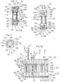
- Fig. 1 is a perspective view of a large test tube;
- Fig. 2 is a perspective view of a small test tube;
- Fig. 3 is a right side perspective view of a test tube carrier embodying the present invention;
- Fig. 4 is a left side perspective view thereof;
- Fig. 5 is a rear elevational view of the carrier;
- Fig. 6 is a front elevational view of the carrier;
- Fig. 7 is a left side elevational view of the carrier;
- Fig. 8 is a right side elevational view of the carrier;
- Fig. 9 is a top plan view of the carrier;
- Fig. 10 is a front elevational view showing a plurality of carriers connected together along a single axis;
- Fig. 11 is a top plan view of a plurality of carriers connected together along a single axis;
- Fig. 12 is a fragmentary, right side elevational view depicting the carrier held within a tracked receiver;
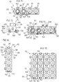
- Fig. 13 is a top plan view depicting a plurality of carriers connected together along a single axis received within a tracked receiver, and depicting one of the carriers engaged by robotic selector elements;
- Fig. 14 is a top plan view of a plurality of carriers connected along a single axis different from the axis of connection depicted in Figs. 10, 11 and 13;
- Fig. 15 is a top plan view of a plurality of carriers connected into a two axis matrix.
- Reference is now made to the drawings, wherein like reference numerals denote like elements throughout the several views. A
test tube carrier 10 embodying the present invention is depicted in various ones of the figures with atest tube 12 carried within. Referring to Figure 1, alarge test tube 12 is depicted, plugged by astopper 14 and withbar code label 16 attached to the side of thetest tube 12. Referring to Figure 2, a smaller test tube 12' is depicted which likewise includes a stopper 14' and label 16'. - Referring to Figures 3 and 4, the
test tube carrier 10 is a unitary piece and broadly includes anupper portion 20, abase 22, a mid-portion 24 extending between theupper portion 20 andbase 22, a side-to-side coupling mechanism 26, front-to-back joining mechanism 28 and aviewing slot 30. - For ease of discussion, the
front 32 of thetest tube carrier 10 is designated as the face of the test tube carrier carrying theviewing slot 30. Theback face 34 of thetest tube carrier 10 is the face opposed to thefront face 32. Theleft face 36 andright face 38 of thetest tube carrier 10 are designated as right and left while viewing thefront face 32 of thetest tube carrier 10. It is understood that the designations front, back, right and left may be changed as the orientation of thetest tube carrier 10 varies. - The
upper portion 20 is formed by exterior surfaces presenting a generally cube-like shape with an embossedarrow 40 carried on the upperplanar surface 42. A generally cylindricalinterior surface 44 defines the upper portion of a testtube receiving cavity 46. A generally squarerecessed opening 48 is presented by theupper portion 20 on theright face 38 of thecarrier 10. The embossedarrow 40 extends from theback face 34 to theinterior surface 44. - The
base 22 is a generally cube-like shape with aplanar bottom floor 50 and generally squarerecessed opening 48 presented on theright face 38 of thecarrier 10. Thebase 22 broadly includes the lower portion of the testtube receiving cavity 46 and opposedtrack receiving grooves 52. Referring to Figure 6, the lower portion of the testtube receiving cavity 46 includes adrainage passage 54 extending from thecavity 46 through thefloor 50 of thebase 22. Referring to Figures 5 and 6, the opposedtrack receiving grooves 52 each include opposedhorizontal track walls flared ends - The mid-portion 24 includes the mid-portion of test
tube receiving cavity 46 defined by a cylindrical test tube receivingbore 64 extending from theupper portion 20 to thebase 22. An outercylindrical surface 66 of mid-portion 24 generally extends around the testtube receiving bore 64. - The side-to-
side coupling mechanism 26 includes anupper coupling mechanism 68 carried by theupper portion 20 and alower coupling mechanism 70 carried by thebase 22. - The
upper coupling mechanism 68 and thelower coupling mechanism 70 each include aboss 72 positioned along theleft face 36 of thetest tube carrier 10, and an opposedboss receiving cavity 74 positioned within therecessed opening 48. Eachboss 72 broadly includes opposed vertical, side surfaces 76, 78, opposed upper and lowercurved surfaces circular indentation 84. The upper and lowercurved surfaces beveled edge 86 along the margin between thecurved surfaces outer margin 88 of theboss 72. Theboss 72 is sized to snap snugly into theboss receiving cavity 74 of anadjacent carrier 10 with a force fit. - Each
boss receiving cavity 74 is defined by opposedarcuate walls flexible tension channels circular well 98. Thetension channels vertical side walls opening 48. Thearcuate walls tension channels curved surfaces boss 72 of anadjacent carrier 10. Thecircular well 98 is centered between thearcuate walls - Referring to Figures 3-9, the front-to-
back joining mechanism 28 includes an upper front-to-back joining mechanism 104 carried by theupper portion 20 and a lower front-to-back joining mechanism 106 carried by thebase 22. The upper front-to-back joining mechanism 104 includes arectangular protrusion 108, opposedprotrusion receiving guide 110, ahorizontal bar 112 extending along theback face 34 of thetest tube carrier 10 and a complementarybar receiving channel 114 presented by thefront face 32 of thetest tube carrier 10. Therectangular protrusion 108 presents opposedbeveled edges rectangular protrusion 108 is sized to fit snugly into theprotrusion receiving guide 110 of an adjacenttest tube carrier 10. Theprotrusion receiving guide 110 includes opposed ledges 120, 122 presented by theviewing slot 30. Thehorizontal bar 112 extends along theback face 34 opposed to thebar receiving channel 114. - The lower joining mechanism 106 includes a generally
rectangular knob 124 carried along theback face 34 of thecarrier 10. Theknob 124 presents beveledmargins viewing slot 30. - The
viewing slot 30, presented along thefront face 32 of thetest tube carrier 10, extends from theupper portion 20 of thetest tube carrier 10 into thebase 22. Opposedslot side walls 130 extend along and defineviewing slot 30. - In operation, the
test tube carrier 10 can be connected to adjacenttest tube carriers 10 as depicted in Figures 10 and 11. A plurality oftest tube carriers 10 are depicted in Figures 10 and 11 as connected in a row through the side-to-side coupling mechanism 26. The side-to-side coupling mechanism 26 connects two adjacenttest tube carriers 10 together by the snapping of theboss 72 of theupper coupling mechanism 68 and theboss 72 of thelower coupling mechanism 70 of afirst carrier 10 into the correspondingboss receiving cavities 74 on theupper portion 20 andbase 22 of an adjacent,second carrier 10. - As depicted in Figure 10, the test
tube receiving cavity 46 is of sufficient diameter to rotatetest tubes 12 placed within the testtube receiving cavity 46 so that thebar code label 16 is easily visible throughviewing slot 30. Any spillage or moisture on thetest tube 12 can pass outside thecarrier 10 through thedrainage passage 54. - Referring to Figure 11, the
bosses 72 of theupper coupling mechanism 68 andlower coupling mechanism 70 of eachcarrier 10 have been connected to the correspondingboss receiving cavities 48 of the adjacenttest tube carrier 10. The beveled edges 86 of eachboss 72 guide thebosses 72 into a force fit with each respectiveboss receiving cavity 74. Thetensions channels arcuate walls curved surfaces boss 72. It will be noted in Figure 11 that the twotest tube carriers 10 on the far left containtest tubes 12, 12' of different sizes while the twotest tube carriers 10 on the right are empty. - Referring to Figure 12, the opposed
track receiving grooves 52 are operably engaged by thecarrier engaging tracks 132 for movement of the carrier along a predetermined path by automated handling equipment. The flared ends 60, 62 of thetrack walls track reciving grooves 52 into operable engagement with thetracks 132. - Referring to Figure 13, a pair of robotic arms 134 are depicted as grasping a selected
test tube carrier 10 as a plurality of connectedtest tube carriers 10 carry thetest tubes 12 through the automatic processing equipment. - The front-to-
back joining mechanisms 42 ofadjacent carriers 10 are depicted in Figure 14 as connecting a plurality oftest tube carriers 10 in a column. The front-to-back joining mechanisms 42 connect eachtest tube carrier 10 to an adjacenttest tube carrier 10 by the insertion of therectangular protrusion 108 of respective upper joining mechanisms 104 snugly into the opposed protrusion receiving guides 110 of adjacenttest tube carriers 10 and by the fitting of therectangular knob 124 of the lower joining mechanisms 106 snugly into the lower portion of theviewing slot 30 of adjacenttest tube carriers 10. In addition, thehorizontal bar 112 of respective carriers are received into thebar receiving channel 114 of adjacenttest tube carriers 10. - Referring to Figure 15, a plurality of
test tube carriers 10 are joined in a two axis matrix. Note that the embossedarrow 40 readily identifies the front of eachcarrier 10. - Having disclosed the subject matter of this invention, it should be apparent that many substitutions, modifications, and variations of the invention are possible in light of the above teachings. It is therefore to be understood that the invention as taught and described herein is only limited to the extent of the breath and scope of the appended claims.
Claims (7)
- A test tube holding device adapted for selective intercoupling with like holding devices for organized storage of a pluraltiy of test tubes, each of said test tubes presenting a test tube longitudinal axis, comprising:
holding means including structure defining an elongated test tube receiving cavity for removably carrying said test tube;
coupling assembly means operably carried by said holding means for operably, selectively, detachably coupling said holding means to said like holding devices. - A test tube holding device as claimed in claim 1, said holding means including structure defining an elongated slot for viewing of said test tube along a substantial portion of said test tube longitudinal axis.
- A test tube holding device as claimed in claim 2, said holding means presenting a first holding means axis transverse to said elongated slot, said coupling assembly means including coupling means for operably, detachably coupling said holding devices along said first holding means axis, whereby the longitudinal axes of each of a plurality of test tubes carried by a plurality of said holding devices joined together by respective coupling assembly means along said first holding means axis are exposed for viewing.
- A test tube holding device as claimed in claim 3, said holding means including a second holding means axis transverse to said first holding means axis, said coupling assembly means including joining means for operably, detachably joining said holding devices along said second axis for two-dimensional coupling of said test tube holding devices and storage of said test tubes.
- A test tube holding device as claimed in claim 3 or claim 4, said coupling means including at least one boss and at least one opposed boss receiving cavity carried by said holding means for mateable coupling of adjacent ones of said holding devices along said first holding means axis.
- A test tube holding device as claimed in claim 5, the boss and boss receiving cavity of adjacent ones of said holding devices being detachably couplable together in a force fit.
- A test tube holding device as claimed in claim 4 or as claimed in claim 5 or claim 6 when dependent on claim 4, said joining means including at least one protrusion carried by said holding means, said protrusion being adapted for mateable reception within the elongated slot of an adjacent one of said like holding device.
Applications Claiming Priority (2)
| Application Number | Priority Date | Filing Date | Title |
|---|---|---|---|
| US91358992A | 1992-07-14 | 1992-07-14 | |
| US913589 | 1992-07-14 |
Publications (3)
| Publication Number | Publication Date |
|---|---|
| EP0579486A2 true EP0579486A2 (en) | 1994-01-19 |
| EP0579486A3 EP0579486A3 (en) | 1994-06-15 |
| EP0579486B1 EP0579486B1 (en) | 1997-03-12 |
Family
ID=25433422
Family Applications (1)
| Application Number | Title | Priority Date | Filing Date |
|---|---|---|---|
| EP93305503A Expired - Lifetime EP0579486B1 (en) | 1992-07-14 | 1993-07-14 | Specimen tube transfer carrier |
Country Status (4)
| Country | Link |
|---|---|
| US (1) | US5397542A (en) |
| EP (1) | EP0579486B1 (en) |
| CA (1) | CA2100434A1 (en) |
| DE (1) | DE69308665T2 (en) |
Cited By (4)
| Publication number | Priority date | Publication date | Assignee | Title |
|---|---|---|---|---|
| EP2509887A4 (en) * | 2009-12-08 | 2013-06-19 | Life Technologies Corp | Packaging systems and methods for transporting vials |
| CN103204381A (en) * | 2012-01-16 | 2013-07-17 | 克罗内斯股份公司 | Carrier Element For Articles Or Containers |
| EP3248684A1 (en) * | 2016-05-24 | 2017-11-29 | Heathrow Scientific LLC | Test tube holding assembly |
| WO2023274463A1 (en) * | 2021-06-30 | 2023-01-05 | Pepperl+Fuchs Se | Device for presenting a code |
Families Citing this family (47)
| Publication number | Priority date | Publication date | Assignee | Title |
|---|---|---|---|---|
| US5575978A (en) | 1992-03-27 | 1996-11-19 | Abbott Laboratories | Sample container segment assembly |
| JP3350163B2 (en) * | 1993-06-25 | 2002-11-25 | 株式会社カイノス | Extraction container holding transfer device |
| DE9411517U1 (en) * | 1994-07-15 | 1995-08-17 | Boehringer Mannheim Gmbh, 68305 Mannheim | Anti-twist device for test tubes |
| US5777303A (en) * | 1994-09-09 | 1998-07-07 | Gay Freres, Vente Et Exportation S.A. | Device for associating test tube samples with electronic labels for storage of identifying data |
| US5672317A (en) * | 1995-04-19 | 1997-09-30 | Roche Diagnostics Systems, Inc. | Analyzer with fixed position bar code reader |
| US5700429A (en) * | 1995-04-19 | 1997-12-23 | Roche Diagnostic Systems, Inc. | Vessel holder for automated analyzer |
| US6066300A (en) * | 1995-07-07 | 2000-05-23 | Bayer Corporation | Reagent handling system and configurable vial carrier for use therein |
| DE19540877C2 (en) * | 1995-11-02 | 1998-02-26 | Byk Sangtec Diagnostica | Modular reagent cartridge |
| FI101610B (en) * | 1995-11-22 | 1998-07-31 | Clids Oy | The sample sensor |
| US5750075A (en) * | 1996-02-15 | 1998-05-12 | Sun International Trading , Ltd. | Chromotography vial |
| US5885529A (en) * | 1996-06-28 | 1999-03-23 | Dpc Cirrus, Inc. | Automated immunoassay analyzer |
| US5821524A (en) * | 1996-08-19 | 1998-10-13 | Pharmacopeia, Inc. | Method and apparatus for reading bar coded tubular members such as cylindrical vials |
| US6171554B1 (en) | 1996-10-02 | 2001-01-09 | Matrix Technologies Corporation | Apparatus and method for alphanumerically identifying and arranging test tubes |
| US6663836B1 (en) | 1996-10-02 | 2003-12-16 | Matrix Technologies Corporation | Apparatus and method for alphanumerically identifying and arranging test tubes |
| CA2287962C (en) | 1997-05-02 | 2007-01-02 | Gen-Probe Incorporated | Reaction receptacle apparatus |
| FR2763396A1 (en) * | 1997-05-15 | 1998-11-20 | Tosoh Corp | DOSING APPARATUS, AND CONTAINER SUPPORT DEVICE FOR USE WITH SAID APPARATUS |
| US6221027B1 (en) * | 1997-10-21 | 2001-04-24 | Isadore Pitesky | Modular allergy testing apparatus |
| USD432245S (en) * | 1999-07-27 | 2000-10-17 | Becton Dickinson And Company | Collection assembly with a specimen label |
| USD444885S1 (en) | 1999-08-06 | 2001-07-10 | Becton, Dickinson And Company | Stackable tube assembly |
| USD444886S1 (en) | 1999-08-06 | 2001-07-10 | Becton, Dickinson And Company | Stackable tube assembly |
| ATE337096T1 (en) * | 1999-10-20 | 2006-09-15 | Gentra Systems Inc | MIXING AND POURING APPARATUS WITH ROTATING ARM AND ASSOCIATED VESSEL |
| USD435663S (en) * | 1999-12-07 | 2000-12-26 | Becton Dickinson And Company | Collection tube with a specimen label |
| USD436182S1 (en) | 1999-12-07 | 2001-01-09 | Becton Dickinson And Company | Collection tube with a specimen label |
| USD435662S (en) * | 1999-12-07 | 2000-12-26 | Becton Dickinson And Company | Collection tube with a specimen label |
| USD436183S1 (en) | 1999-12-14 | 2001-01-09 | Becton Dickinson And Company | Collection tube with a specimen label |
| USD435664S (en) * | 2000-02-03 | 2000-12-26 | Becton Dickinson And Company | Collection tube with a specimen label |
| US6435582B1 (en) | 2000-07-31 | 2002-08-20 | Motoman, Inc. | Object manipulator and manipulation system |
| US7070053B1 (en) * | 2000-09-05 | 2006-07-04 | Cv Holdings Llc | System, method, and apparatuses for maintaining, tracking, transporting and identifying the integrity of a disposable specimen container with a re-usable transponder |
| US7666363B2 (en) * | 2001-09-05 | 2010-02-23 | Quest Diagnostics Investments Incorporated | Reagent cartridge |
| JP2005164509A (en) * | 2003-12-05 | 2005-06-23 | Hitachi High-Technologies Corp | Reagent container |
| ITFI20040170A1 (en) | 2004-07-30 | 2004-10-30 | Everex S R L | SUPPORT ELEMENT FOR TEST TUBES AND SIMILAR |
| GB0425786D0 (en) * | 2004-11-24 | 2004-12-22 | Dubois Ltd | Packaging article |
| ATE519682T1 (en) * | 2006-08-18 | 2011-08-15 | Brother Max Ltd | FOOD CONTAINERS |
| US8357538B2 (en) * | 2007-04-06 | 2013-01-22 | Qiagen Gaithersburg, Inc. | Automated assay and system |
| US8703492B2 (en) | 2007-04-06 | 2014-04-22 | Qiagen Gaithersburg, Inc. | Open platform hybrid manual-automated sample processing system |
| WO2010132045A1 (en) * | 2009-05-15 | 2010-11-18 | Hamilton Company | Shift and scan test tube rack apparatus and method |
| USD639445S1 (en) * | 2009-06-26 | 2011-06-07 | Labcon, North America | Container with label |
| US9953141B2 (en) | 2009-11-18 | 2018-04-24 | Becton, Dickinson And Company | Laboratory central control unit method and system |
| US8985347B2 (en) * | 2011-07-29 | 2015-03-24 | Alan S. Thompson | Linear spice rack |
| WO2013063431A1 (en) * | 2011-10-28 | 2013-05-02 | Lightbulb, Llc | Toothbrush holder |
| US20150108076A1 (en) * | 2013-10-21 | 2015-04-23 | Health Diagnostic Laboratory, Inc. | Test tube rack insert device |
| US9381516B2 (en) * | 2014-01-27 | 2016-07-05 | Gary L. Sharpe | Vial transport element and assembly |
| US9868555B2 (en) * | 2014-04-28 | 2018-01-16 | Robert F. LiVolsi | Systems and methods for filling inoculations |
| USD773070S1 (en) * | 2015-02-24 | 2016-11-29 | Good Start Genetics, Inc. | Device for barcoding individual wells and vessels |
| CN113275060B (en) * | 2021-05-19 | 2022-05-31 | 广东轻工职业技术学院 | Mistake proofing application of sample device for molecular biology |
| USD1033540S1 (en) * | 2021-10-15 | 2024-07-02 | Gourgen AMBARTSOUMIAN | Label |
| USD1033539S1 (en) * | 2021-10-15 | 2024-07-02 | Gourgen AMBARTSOUMIAN | Label |
Family Cites Families (21)
| Publication number | Priority date | Publication date | Assignee | Title |
|---|---|---|---|---|
| BE354629A (en) * | 1926-06-04 | |||
| US3350946A (en) * | 1964-12-29 | 1967-11-07 | Technicon Instr | Sample containers for analysis apparatus |
| US3883308A (en) * | 1967-05-12 | 1975-05-13 | Centre Nat Rech Scient | Apparatus for analysing liquid substances likely to form agglutinates |
| US3854879A (en) * | 1973-07-27 | 1974-12-17 | Coulter Electronics | Sample identification and test data correlation method and apparatus |
| US3909203A (en) * | 1974-08-04 | 1975-09-30 | Anatronics Corp | Analysis system having random identification and labeling system |
| DE2722672A1 (en) * | 1977-05-18 | 1978-11-30 | Siemens Ag | TRANSPORT CHAIN FOR LIQUID SAMPLING VESSELS |
| US4595562A (en) * | 1981-07-20 | 1986-06-17 | American Hospital Supply Corporation | Loading and transfer assembly for chemical analyzer |
| GB2116711B (en) * | 1982-03-17 | 1985-07-31 | Vickers Plc | Automatic chemical analysis |
| US4480745A (en) * | 1983-04-13 | 1984-11-06 | Goodmark Foods, Inc. | Interlocking modular display rack system, component units therefor, and methods |
| DE3464971D1 (en) * | 1983-05-10 | 1987-08-27 | Jouan Sa | Modular holder for containers of different sizes, in particular for analyzers |
| US4542930A (en) * | 1984-01-06 | 1985-09-24 | Adams Mark S | Rigid tube type beverage can carrier |
| US4873633A (en) * | 1985-10-18 | 1989-10-10 | Cetus Corporation | User controlled off-center light absorbance reading adjuster in a liquid handling and reaction system |
| US4944924A (en) * | 1987-06-11 | 1990-07-31 | Technicon Instruments Corporation | Test tube holder |
| US4861553A (en) * | 1987-06-11 | 1989-08-29 | Technicon Instruments Corporation | Automatic sampling system |
| US4919296A (en) * | 1987-07-20 | 1990-04-24 | Janet A. Kirsh | Container |
| DE3735708A1 (en) * | 1987-10-22 | 1989-05-03 | Maprotec Probenverteilsysteme | CONTROL UNIT FOR REAGENT, SAMPLING TUBES OR THE LIKE |
| DE68925493T2 (en) * | 1988-05-11 | 1996-05-30 | Du Pont Canada | Device for collecting blood |
| US5008082A (en) * | 1988-08-25 | 1991-04-16 | Eastman Kodak Company | Analyzers using linear sample trays with random access |
| EP0414644A3 (en) * | 1989-08-25 | 1991-08-28 | Greiner Vibrograf Ag | Chain fashioned holding device having tubes for holding a tubular vessel each |
| US5050755A (en) * | 1990-03-28 | 1991-09-24 | Strawder Glenn G | Modular receptacles such as trash cans |
| US5137693A (en) * | 1990-07-30 | 1992-08-11 | Miles Inc. | Spring biased test tube holder |
-
1993
- 1993-07-13 CA CA002100434A patent/CA2100434A1/en not_active Abandoned
- 1993-07-14 DE DE69308665T patent/DE69308665T2/en not_active Expired - Fee Related
- 1993-07-14 EP EP93305503A patent/EP0579486B1/en not_active Expired - Lifetime
-
1994
- 1994-07-29 US US08/283,395 patent/US5397542A/en not_active Expired - Lifetime
Cited By (9)
| Publication number | Priority date | Publication date | Assignee | Title |
|---|---|---|---|---|
| EP2509887A4 (en) * | 2009-12-08 | 2013-06-19 | Life Technologies Corp | Packaging systems and methods for transporting vials |
| CN103204381A (en) * | 2012-01-16 | 2013-07-17 | 克罗内斯股份公司 | Carrier Element For Articles Or Containers |
| EP2615047A1 (en) * | 2012-01-16 | 2013-07-17 | Krones Aktiengesellschaft | Carrier element for articles or containers |
| CN103204381B (en) * | 2012-01-16 | 2015-07-29 | 克罗内斯股份公司 | For the load-carrying unit of article or container |
| EP3248684A1 (en) * | 2016-05-24 | 2017-11-29 | Heathrow Scientific LLC | Test tube holding assembly |
| US10207273B2 (en) | 2016-05-24 | 2019-02-19 | Heathrow Scientific Llc | Test tube holding assembly |
| WO2023274463A1 (en) * | 2021-06-30 | 2023-01-05 | Pepperl+Fuchs Se | Device for presenting a code |
| EP4163823A1 (en) * | 2021-06-30 | 2023-04-12 | Pepperl+Fuchs SE | Device for presenting a code |
| US12236299B2 (en) | 2021-06-30 | 2025-02-25 | Pepperl+Fuchs Se | Device for presenting a code |
Also Published As
| Publication number | Publication date |
|---|---|
| US5397542A (en) | 1995-03-14 |
| CA2100434A1 (en) | 1994-01-15 |
| EP0579486B1 (en) | 1997-03-12 |
| EP0579486A3 (en) | 1994-06-15 |
| DE69308665D1 (en) | 1997-04-17 |
| DE69308665T2 (en) | 1997-06-19 |
Similar Documents
| Publication | Publication Date | Title |
|---|---|---|
| US5397542A (en) | Specimen tube transfer carrier | |
| CA1235093A (en) | Cassette for supporting test tubes of different diameters and/or lengths | |
| US5651941A (en) | Sample tube carrier | |
| US7000785B2 (en) | Tube rack accommodating a range of tube diameters | |
| US4124122A (en) | Test tube rack | |
| AU675605B2 (en) | Sample tube rack and adapter | |
| US5687849A (en) | Test tube cassette for accommodating different tube sizes | |
| EP3167962B1 (en) | Sample tube rack and sample tube analysing system | |
| CA1230327A (en) | Method and apparatus for transporting carriers of sealed sample tubes and mixing the samples | |
| US5036989A (en) | Test tube support system | |
| EP0365828B1 (en) | Rack for sample containers | |
| US8017093B2 (en) | Method and system for transporting and storing multiple reagent packs and reagent packs used therein | |
| EP2148204B1 (en) | A laboratory storage and retrieval system and a method to handle laboratory sample tubes | |
| US5540334A (en) | Beaker transport tray | |
| EP1883475B1 (en) | Sample tube holder | |
| US4938369A (en) | Multiple-option test tube support system | |
| US4207289A (en) | Sample tube holder | |
| US20200122149A1 (en) | Apparatus and method for handling sample containers | |
| JP2003329693A (en) | Cartridge rack structure for dispensing device | |
| US4636477A (en) | Procedure for loading cuvette packages into an instrument, and cuvette package | |
| CN107257712A (en) | Sample container rack, method for locking sample container in sample container rack and sample container rack system | |
| JPS63502929A (en) | modular storage system | |
| US20020068022A1 (en) | Mini-tube rack | |
| EP1232011A4 (en) | Pipette tip having plural channels and a titration kit therefore | |
| US4202289A (en) | Specimen processing apparatus for microscopy |
Legal Events
| Date | Code | Title | Description |
|---|---|---|---|
| PUAI | Public reference made under article 153(3) epc to a published international application that has entered the european phase |
Free format text: ORIGINAL CODE: 0009012 |
|
| AK | Designated contracting states |
Kind code of ref document: A2 Designated state(s): BE DE ES FR GB IT NL |
|
| PUAL | Search report despatched |
Free format text: ORIGINAL CODE: 0009013 |
|
| AK | Designated contracting states |
Kind code of ref document: A3 Designated state(s): BE DE ES FR GB IT NL |
|
| 17P | Request for examination filed |
Effective date: 19941001 |
|
| 17Q | First examination report despatched |
Effective date: 19950503 |
|
| GRAG | Despatch of communication of intention to grant |
Free format text: ORIGINAL CODE: EPIDOS AGRA |
|
| GRAH | Despatch of communication of intention to grant a patent |
Free format text: ORIGINAL CODE: EPIDOS IGRA |
|
| RIN1 | Information on inventor provided before grant (corrected) |
Inventor name: EUMARIAN, CHARLES Inventor name: NELMS,GEORGE E. |
|
| GRAH | Despatch of communication of intention to grant a patent |
Free format text: ORIGINAL CODE: EPIDOS IGRA |
|
| GRAA | (expected) grant |
Free format text: ORIGINAL CODE: 0009210 |
|
| AK | Designated contracting states |
Kind code of ref document: B1 Designated state(s): BE DE ES FR GB IT NL |
|
| PG25 | Lapsed in a contracting state [announced via postgrant information from national office to epo] |
Ref country code: NL Free format text: LAPSE BECAUSE OF FAILURE TO SUBMIT A TRANSLATION OF THE DESCRIPTION OR TO PAY THE FEE WITHIN THE PRESCRIBED TIME-LIMIT Effective date: 19970312 Ref country code: IT Free format text: LAPSE BECAUSE OF FAILURE TO SUBMIT A TRANSLATION OF THE DESCRIPTION OR TO PAY THE FEE WITHIN THE PRE;WARNING: LAPSES OF ITALIAN PATENTS WITH EFFECTIVE DATE BEFORE 2007 MAY HAVE OCCURRED AT ANY TIME BEFORE 2007. THE CORRECT EFFECTIVE DATE MAY BE DIFFERENT FROM THE ONE RECORDED.SCRIBED TIME-LIMIT Effective date: 19970312 Ref country code: FR Effective date: 19970312 Ref country code: ES Free format text: THE PATENT HAS BEEN ANNULLED BY A DECISION OF A NATIONAL AUTHORITY Effective date: 19970312 Ref country code: BE Effective date: 19970312 |
|
| REF | Corresponds to: |
Ref document number: 69308665 Country of ref document: DE Date of ref document: 19970417 |
|
| PGFP | Annual fee paid to national office [announced via postgrant information from national office to epo] |
Ref country code: DE Payment date: 19970718 Year of fee payment: 5 |
|
| NLV1 | Nl: lapsed or annulled due to failure to fulfill the requirements of art. 29p and 29m of the patents act | ||
| EN | Fr: translation not filed | ||
| PLBE | No opposition filed within time limit |
Free format text: ORIGINAL CODE: 0009261 |
|
| STAA | Information on the status of an ep patent application or granted ep patent |
Free format text: STATUS: NO OPPOSITION FILED WITHIN TIME LIMIT |
|
| 26N | No opposition filed | ||
| PGFP | Annual fee paid to national office [announced via postgrant information from national office to epo] |
Ref country code: GB Payment date: 19980710 Year of fee payment: 6 |
|
| PG25 | Lapsed in a contracting state [announced via postgrant information from national office to epo] |
Ref country code: DE Free format text: LAPSE BECAUSE OF NON-PAYMENT OF DUE FEES Effective date: 19990501 |
|
| PG25 | Lapsed in a contracting state [announced via postgrant information from national office to epo] |
Ref country code: GB Free format text: LAPSE BECAUSE OF NON-PAYMENT OF DUE FEES Effective date: 19990714 |
|
| GBPC | Gb: european patent ceased through non-payment of renewal fee |
Effective date: 19990714 |