EP0579474B1 - Row feeder for distribution of nuts - Google Patents
Row feeder for distribution of nuts Download PDFInfo
- Publication number
- EP0579474B1 EP0579474B1 EP93305464A EP93305464A EP0579474B1 EP 0579474 B1 EP0579474 B1 EP 0579474B1 EP 93305464 A EP93305464 A EP 93305464A EP 93305464 A EP93305464 A EP 93305464A EP 0579474 B1 EP0579474 B1 EP 0579474B1
- Authority
- EP
- European Patent Office
- Prior art keywords
- nuts
- stroking
- guide passage
- pusher
- main unit
- Prior art date
- Legal status (The legal status is an assumption and is not a legal conclusion. Google has not performed a legal analysis and makes no representation as to the accuracy of the status listed.)
- Expired - Lifetime
Links
Images


Classifications
-
- B—PERFORMING OPERATIONS; TRANSPORTING
- B23—MACHINE TOOLS; METAL-WORKING NOT OTHERWISE PROVIDED FOR
- B23P—METAL-WORKING NOT OTHERWISE PROVIDED FOR; COMBINED OPERATIONS; UNIVERSAL MACHINE TOOLS
- B23P19/00—Machines for simply fitting together or separating metal parts or objects, or metal and non-metal parts, whether or not involving some deformation; Tools or devices therefor so far as not provided for in other classes
- B23P19/001—Article feeders for assembling machines
- B23P19/003—Escapement mechanisms used therewith
-
- B—PERFORMING OPERATIONS; TRANSPORTING
- B23—MACHINE TOOLS; METAL-WORKING NOT OTHERWISE PROVIDED FOR
- B23P—METAL-WORKING NOT OTHERWISE PROVIDED FOR; COMBINED OPERATIONS; UNIVERSAL MACHINE TOOLS
- B23P19/00—Machines for simply fitting together or separating metal parts or objects, or metal and non-metal parts, whether or not involving some deformation; Tools or devices therefor so far as not provided for in other classes
- B23P19/04—Machines for simply fitting together or separating metal parts or objects, or metal and non-metal parts, whether or not involving some deformation; Tools or devices therefor so far as not provided for in other classes for assembling or disassembling parts
- B23P19/06—Screw or nut setting or loosening machines
- B23P19/062—Pierce nut setting machines
-
- B—PERFORMING OPERATIONS; TRANSPORTING
- B23—MACHINE TOOLS; METAL-WORKING NOT OTHERWISE PROVIDED FOR
- B23Q—DETAILS, COMPONENTS, OR ACCESSORIES FOR MACHINE TOOLS, e.g. ARRANGEMENTS FOR COPYING OR CONTROLLING; MACHINE TOOLS IN GENERAL CHARACTERISED BY THE CONSTRUCTION OF PARTICULAR DETAILS OR COMPONENTS; COMBINATIONS OR ASSOCIATIONS OF METAL-WORKING MACHINES, NOT DIRECTED TO A PARTICULAR RESULT
- B23Q7/00—Arrangements for handling work specially combined with or arranged in, or specially adapted for use in connection with, machine tools, e.g. for conveying, loading, positioning, discharging, sorting
- B23Q7/10—Arrangements for handling work specially combined with or arranged in, or specially adapted for use in connection with, machine tools, e.g. for conveying, loading, positioning, discharging, sorting by means of magazines
-
- B—PERFORMING OPERATIONS; TRANSPORTING
- B65—CONVEYING; PACKING; STORING; HANDLING THIN OR FILAMENTARY MATERIAL
- B65G—TRANSPORT OR STORAGE DEVICES, e.g. CONVEYORS FOR LOADING OR TIPPING, SHOP CONVEYOR SYSTEMS OR PNEUMATIC TUBE CONVEYORS
- B65G47/00—Article or material-handling devices associated with conveyors; Methods employing such devices
- B65G47/74—Feeding, transfer, or discharging devices of particular kinds or types
- B65G47/82—Rotary or reciprocating members for direct action on articles or materials, e.g. pushers, rakes, shovels
Definitions
- the invention relates to a row feeder for distribution of nuts.
- Such a row feeder can, for example, successively distribute nuts, as mechanical parts, from a delivery source to various nut attaching apparatus such as self-piercing nut assembling apparatus.
- Self-piercing nuts are widely used and are usually affixed to metal plates such as those which are typically incorporated in automobiles.
- the self-piercing nut has an end face serving as a punch against the metal plate, thereby causing the nut to punch an installation aperture in the metal plate and simultaneously to fix the nut in place on the plate.
- the nut supplying apparatus widely employ vibrating feeders.
- the popular self-piercing nuts (hereinafter simply called “nuts”) can be applied to various metal places, typically to those which construct a car body. It is usual practice to attach in a one shot operation many such nuts to one metal plate as a workpiece, which in many cases is subjected at the same time to punching, blanking, trimming and/or partial drawing processes. Generally, several sets of the nut assembling apparatus are built into one press together with its main moulds or parts. Any passage through which the nuts are fed to such self-piercing nut assembling apparatus must not interfere with any punching dies or the like in the press. Thus, nut feeders are provided in the vicinity of the press to deliver the nuts through flexible chute hoses to the respective nut assembling apparatus.
- chute hoses may have to extend into the press and each of many nut feeders disposed near it must comprise a transfer device to feed the nuts into the flexible chute hose.
- a transfer device to feed the nuts into the flexible chute hose.
- French Published Patent Application FR-A-2 596 311 describes a row-feeder for the distribution of nuts having a main unit, a guide passage to receive a certain number of successively delivered nuts, and a plurality of distribution channels, to which individual nuts are directed from the guide passage by reciprocating stroking pushers.
- Individual feed chutes are connected to the distribution channels, enabling the nuts to be fed directly to the part to which they are to be attached.
- a row feeder for distribution of nuts comprising:
- the stroking pushers can be controlled to operate in response to nut attaching apparatus such as self-piercing nut assembling apparatus which are supplied with the nuts.
- Each stroking pusher preferably has a lower face formed with a cutout, such that the successively delivered nuts are not prevented from advancing forward along the guide passage while any stroking pusher is disposed across it to enter the distribution passage.
- the stroking pushers operate individually so that some of them can be rested if desired.
- nuts which are successively delivered in series to the guide passage will be transferred by the stroking pushers one by one into the distribution passages connected to the feed chutes leading to the nut assembling apparatus or the like.
- Figure 1 illustrates a system which includes a row feeder 10 for distributing nuts, for example self-piercing nuts.
- the row feeder 10 is provided in association with a press 1 in which sets of nut attaching apparatus 7 as detailed below are incorporated.
- a nut supplier 2 disposed in the vicinity of the press 1 will arrange the self-piercing nuts to take their regulated position, before they are delivered in a successive manner to the row feeder 10 through a flexible chute hose 3.
- a pneumatically driven lift 4 is associated with the chute hose 3 at an appropriate region thereof.
- the self-piercing nuts are elevated to a peak 5 of the hose higher than the row feeder 10 and then descend thereto due to gravitational force.
- Sensors S 1 and S 2 for detecting the nuts are disposed along a descent portion 3 a of the chute hose 3, to check that the descent portion 3 a is always filled with a predetermined number of the nuts.
- the weight of all the nuts within the descent portion 3 a will act on leading ones of them, so that they are delivered to the row feeder 10 in a continuous manner.
- each self-piercing nut assembling apparatus 7 is secured to and between a lower mould 8 and an upper mould 9, together with the usual dies and punches not shown, wherein the lower mould is carried by a bolster 1 a and the upper mould is detachably attached to a ram 1 b of the press 1.
- the self-piercing nut assembling apparatus 7 do not directly relate to the present invention.
- further details on its structure will not be given here, but only noting than an end face of each nut which will be fed through a feed chute 13 (described below) acts as a kind of punch.
- the nut thus punches a hole through a metal plate held on a swaging die and is simultaneously made integral with the plate.
- the row feeder 10 for distributing the nuts in this embodiment is carried partly by the ram 1 b and also partly by the upper mould 9 of the press 1, as shown in Figures 4 to 7 and described below in detail referring thereto.
- the row feeder 10 is composed of a main unit 11 and a joint member 12, with the main unit 11 connected to the chute hose 3 through which a plurality of the self-piercing nuts (abbreviated as “nuts") "N" are successively delivered to the main unit 11.
- the joint member 12 is constructed to hold in place a plurality of feed chutes 13 arrange side by side and at given intervals therebetween, with the feed chutes being connected to the main unit 11.
- the main unit 11 may be united integral with the joint member 12, but they are preferably made separable from one another for easier removal for changing of the upper mould 9 from the ram 1 b in the press 1, as in the illustrated embodiment.
- the main unit 11 comprises a guide passage 14 formed thereon to receive a number of successively supplied nuts "N" in series, a plurality of distribution passages 15 similarly formed on the main unit 11 and each extending from and perpendicular to the guide passage 14, and the feed chutes 13 each secured to the corresponding distribution passage 15 in communication therewith.
- a plurality of stroking pushers 16 to push the nuts towards the respective distribution passages 15 are provided on the main body.
- Each of the stroking pushers 16 is operatively connected by a pin 19 to a piston rod 18 of a pneumatic cylinder 17 which is fixed on the main unit 11.
- a coiled spring 20 wound around the pin 19 always urges the stroking pusher 16 in a direction such that its forward free end 16 a tends to take a lower position.
- the stroking pushers 16 are thus allowed to advance forwards across the guide passage 14 and into the respective distribution passages 15, and then to return to their home positions behind the guide passage 14 (see Figures 5 and 6). It will be understood that the pushers 16 are driven in response to the self-piercing nut assembling apparatus 7.
- the pushers 16 have their lower faces each formed with a cutout 21 which enables free and unhindered feeding of nuts "N" along the guide passage 14 even while the stroking pushers 16 are operating across this passage and into the distribution passages 15.
- the main unit 11 of the described structure is fixedly attached to the ram 1 b by means of a bracket 31, in a manner as shown in Figure 2.
- a swingable arm 34 carrying the joint member 12 is journalled on a bracket 32 by a pivot 33, with this bracket being fixed to the upper mould 9.
- a pneumatically driven cylinder 35 drives the swingable arm 34 to rotate through an angle about the pivot 33, so that the arm 34 is swung between a horizontal position and an inclined position.
- the arm 34 will make such a pivotal motion to tilt the joint member 12 when the upper mould 9 is detached from the ram 1 b and automatically replaced with another upper mould.
- Figure 7 illustrates a device which may preferably be employed for a surer protection of nuts “N” from unintentional droppage.
- the device in Figure 7 comprises a pawl 36 which is disposed on the joint member 12 and engageable with a threaded bore 22 of the nut "N" held in the feed chute 13 and disposed nearest its entrance end 13 a .
- a bracket 37 secured to the joint member 12 has a pin 38 about which the pawl 36 can pivot, and a spring 39 wound around the pin 38, acts on the pawl 36 and urges its end downwards.
- the upper mould 9 will be set in place at first on the ram 1 b . Then, the swingable arm 34 will be driven causing the joint member 12 to take its horizontal position.
- the feed chutes 13 have thus their entrance ends 13 a aligned in communication with the respective distribution passages 15 in the main unit 11.
- the pneumatic cylinder 17 will actuate the stroking pusher 16 to make one reciprocation in response to one operation of the self-piercing nut assembling apparatus 7.
- the forward free end 16 a of the pusher 16 advancing forwards will thus push the nut "N" out of the guide passage 14 into the distribution passage 15, whereby the nut "N" enters the feed chute 13 through its entrance end 13 a .
- the stroking pusher 16 Upon returning to its rearmost home position, the stroking pusher 16 will be clicked downwards by the spring 20 shown in Figure 6, whereby the free end 16 a comes into contact with, or is positioned close to, the rearward surface of the nut "N" which has to be pushed next out of the guide passage 14.
- main unit 11 and the joint member 12 may alternatively be vertically disposed up and down if the mounting space for them so compels or it is preferred to do so.
- the row feeder provided herein can be used not only for feeding the self-piercing nuts “N” to the illustrated nut assembling apparatus 7 but also for distributing ordinary nuts, for example to a plurality of nut welders.
- the described row feeder can realize an efficient distribution of nuts to a plurality of the nut attaching apparatus such as those for self-piercing nuts.
Landscapes
- Engineering & Computer Science (AREA)
- Mechanical Engineering (AREA)
- Automatic Assembly (AREA)
- Compositions Of Macromolecular Compounds (AREA)
- Tires In General (AREA)
Description
- The invention relates to a row feeder for distribution of nuts.
- Such a row feeder can, for example, successively distribute nuts, as mechanical parts, from a delivery source to various nut attaching apparatus such as self-piercing nut assembling apparatus.
- Self-piercing nuts are widely used and are usually affixed to metal plates such as those which are typically incorporated in automobiles. The self-piercing nut has an end face serving as a punch against the metal plate, thereby causing the nut to punch an installation aperture in the metal plate and simultaneously to fix the nut in place on the plate. In order to automate the nut attaching operation, the nut supplying apparatus widely employ vibrating feeders.
- The popular self-piercing nuts (hereinafter simply called "nuts") can be applied to various metal places, typically to those which construct a car body. It is usual practice to attach in a one shot operation many such nuts to one metal plate as a workpiece, which in many cases is subjected at the same time to punching, blanking, trimming and/or partial drawing processes. Generally, several sets of the nut assembling apparatus are built into one press together with its main moulds or parts. Any passage through which the nuts are fed to such self-piercing nut assembling apparatus must not interfere with any punching dies or the like in the press. Thus, nut feeders are provided in the vicinity of the press to deliver the nuts through flexible chute hoses to the respective nut assembling apparatus. Due to provision of several of such apparatus in one press, many chute hoses may have to extend into the press and each of many nut feeders disposed near it must comprise a transfer device to feed the nuts into the flexible chute hose. As a result, not only usual works for changing or checking a press mould and/or maintenance work thereof but also operations for loading and unloading the press with a workpiece are rendered intricate. Further, the works for connecting to and disconnecting from the press many of the chute hoses are likewise made complicated, while still other operations and the operator's movement around the press are hindered. In addition, since an automatic mould exchanger in modern large-scaled presses usually takes considerable space, thereby leaving a little space for the nut feeders, it is considered very difficult and has been regarded as almost impossible to automate the connection and dis-connection of a plurality of the chute hoses to and from the press mould.
- French Published Patent Application FR-A-2 596 311 describes a row-feeder for the distribution of nuts having a main unit, a guide passage to receive a certain number of successively delivered nuts, and a plurality of distribution channels, to which individual nuts are directed from the guide passage by reciprocating stroking pushers. Individual feed chutes are connected to the distribution channels, enabling the nuts to be fed directly to the part to which they are to be attached.
- According to the invention there is provided a row feeder for distribution of nuts, the row feeder comprising:
- a main unit;
- a guide passage formed on the main unit so as to receive a number of successively delivered nuts in a series;
- a plurality of distribution passages formed in the main unit and each extending from and perpendicular to the guide passage;
- stroking pushers each reciprocable between its home position and its extended position across the guide passage so as to transfer the nuts therein to the respective distribution passages;
- drivers causing the respective stroking pushers to reciprocate; and
- individual feed chutes respectively connected to the distribution passages,
- The stroking pushers can be controlled to operate in response to nut attaching apparatus such as self-piercing nut assembling apparatus which are supplied with the nuts.
- Each stroking pusher preferably has a lower face formed with a cutout, such that the successively delivered nuts are not prevented from advancing forward along the guide passage while any stroking pusher is disposed across it to enter the distribution passage.
- It may be advantageous for an easier control of the overall system that the stroking pushers operate individually so that some of them can be rested if desired.
- In the row feeder constructed as above, nuts which are successively delivered in series to the guide passage will be transferred by the stroking pushers one by one into the distribution passages connected to the feed chutes leading to the nut assembling apparatus or the like.
- The invention is diagrammatically illustrated by way of example in the accompanying drawings, in which:-
- Figure 1 is a side elevation schematically showing a manufacturing system in use, which system employs a row feeder according to the invention;
- Figure 2 is an enlarged cross section of parts of the system in one of its states;
- Figure 3 similarly is an enlarged cross section of parts in another state of the system;
- Figure 4 is a plan view of a row feeder according to the invention for distributing nuts;
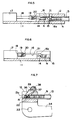
- Figure 5 is a cross section taken on the line 5-5 in Figure 4 and showing a stroking pusher in detail;
- Figure 6 is a cross section similar to Figure 5, but showing the stroking pusher at its home position; and
- Figure 7 is a front elevation showing partly in cross section a joint member which is included in the system.
- Referring to the drawings, Figure 1 illustrates a system which includes a
row feeder 10 for distributing nuts, for example self-piercing nuts. Therow feeder 10 is provided in association with a press 1 in which sets ofnut attaching apparatus 7 as detailed below are incorporated. A nut supplier 2 disposed in the vicinity of the press 1 will arrange the self-piercing nuts to take their regulated position, before they are delivered in a successive manner to therow feeder 10 through aflexible chute hose 3. A pneumatically driven lift 4 is associated with thechute hose 3 at an appropriate region thereof. The self-piercing nuts are elevated to apeak 5 of the hose higher than therow feeder 10 and then descend thereto due to gravitational force. Sensors S1 and S2 for detecting the nuts are disposed along adescent portion 3a of thechute hose 3, to check that thedescent portion 3a is always filled with a predetermined number of the nuts. The weight of all the nuts within thedescent portion 3a will act on leading ones of them, so that they are delivered to therow feeder 10 in a continuous manner. - As shown in Figure 2, each self-piercing
nut assembling apparatus 7 is secured to and between alower mould 8 and an upper mould 9, together with the usual dies and punches not shown, wherein the lower mould is carried by a bolster 1a and the upper mould is detachably attached to a ram 1b of the press 1. Usually, several, for example more than ten,such apparatus 7 are mounted on one press 1, though only one of them is illustrated in the drawings. The self-piercingnut assembling apparatus 7 do not directly relate to the present invention. Thus, further details on its structure will not be given here, but only noting than an end face of each nut which will be fed through a feed chute 13 (described below) acts as a kind of punch. The nut thus punches a hole through a metal plate held on a swaging die and is simultaneously made integral with the plate. - The
row feeder 10 for distributing the nuts in this embodiment is carried partly by the ram 1b and also partly by the upper mould 9 of the press 1, as shown in Figures 4 to 7 and described below in detail referring thereto. - The
row feeder 10 is composed of a main unit 11 and ajoint member 12, with the main unit 11 connected to thechute hose 3 through which a plurality of the self-piercing nuts (abbreviated as "nuts") "N" are successively delivered to the main unit 11. Thejoint member 12 is constructed to hold in place a plurality offeed chutes 13 arrange side by side and at given intervals therebetween, with the feed chutes being connected to the main unit 11. The main unit 11 may be united integral with thejoint member 12, but they are preferably made separable from one another for easier removal for changing of the upper mould 9 from the ram 1b in the press 1, as in the illustrated embodiment. The main unit 11 comprises aguide passage 14 formed thereon to receive a number of successively supplied nuts "N" in series, a plurality ofdistribution passages 15 similarly formed on the main unit 11 and each extending from and perpendicular to theguide passage 14, and thefeed chutes 13 each secured to thecorresponding distribution passage 15 in communication therewith. A plurality of strokingpushers 16 to push the nuts towards therespective distribution passages 15 are provided on the main body. Each of thestroking pushers 16 is operatively connected by apin 19 to apiston rod 18 of apneumatic cylinder 17 which is fixed on the main unit 11. A coiledspring 20 wound around thepin 19 always urges thestroking pusher 16 in a direction such that its forwardfree end 16a tends to take a lower position. Thestroking pushers 16 are thus allowed to advance forwards across theguide passage 14 and into therespective distribution passages 15, and then to return to their home positions behind the guide passage 14 (see Figures 5 and 6). It will be understood that thepushers 16 are driven in response to the self-piercingnut assembling apparatus 7. Thepushers 16 have their lower faces each formed with acutout 21 which enables free and unhindered feeding of nuts "N" along theguide passage 14 even while thestroking pushers 16 are operating across this passage and into thedistribution passages 15. - In the
row feeder 10 in this case, the main unit 11 of the described structure is fixedly attached to the ram 1b by means of abracket 31, in a manner as shown in Figure 2. Aswingable arm 34 carrying thejoint member 12 is journalled on abracket 32 by apivot 33, with this bracket being fixed to the upper mould 9. A pneumatically drivencylinder 35 drives theswingable arm 34 to rotate through an angle about thepivot 33, so that thearm 34 is swung between a horizontal position and an inclined position. As can be seen in Figure 3, thearm 34 will make such a pivotal motion to tilt thejoint member 12 when the upper mould 9 is detached from the ram 1b and automatically replaced with another upper mould. Thus, anentrance end 13a of thefeed chute 13 carried by thejoint member 12 will adopt an obliquely raised position, such that the nuts "N" within the feed chute will not fall out of theentrance end 13a. Figure 7 illustrates a device which may preferably be employed for a surer protection of nuts "N" from unintentional droppage. The device in Figure 7 comprises apawl 36 which is disposed on thejoint member 12 and engageable with a threadedbore 22 of the nut "N" held in thefeed chute 13 and disposed nearest itsentrance end 13a. Abracket 37 secured to thejoint member 12 has apin 38 about which thepawl 36 can pivot, and aspring 39 wound around thepin 38, acts on thepawl 36 and urges its end downwards. - In operation, the upper mould 9 will be set in place at first on the ram 1b. Then, the
swingable arm 34 will be driven causing thejoint member 12 to take its horizontal position. The feed chutes 13 have thus their entrance ends 13a aligned in communication with therespective distribution passages 15 in the main unit 11. In this state, thepneumatic cylinder 17 will actuate the strokingpusher 16 to make one reciprocation in response to one operation of the self-piercingnut assembling apparatus 7. The forwardfree end 16a of thepusher 16 advancing forwards will thus push the nut "N" out of theguide passage 14 into thedistribution passage 15, whereby the nut "N" enters thefeed chute 13 through itsentrance end 13a. Even while the stroking pusher is operating in this way, delivery of the following nuts "N" to theguide passage 14 will not be interrupted but can continue by virtue of thecutout 21 formed on the lower face of thepusher 16. This will diminish the queuing time for the nuts "N" to be delivered to theguide passage 14, thus minimizing time lost in supplying them through theflexible chute hose 3. On the other hand, when thepusher 16 is retracted, its bump-shapedfree end 16a will be pulled backwards and slidingly over the upper face of the nut "N" which is waiting at that time in theguide passage 14, in such a manner as the broken line shows in Figure 5. Upon returning to its rearmost home position, the strokingpusher 16 will be clicked downwards by thespring 20 shown in Figure 6, whereby thefree end 16a comes into contact with, or is positioned close to, the rearward surface of the nut "N" which has to be pushed next out of theguide passage 14. - If any one of the
nut assembling apparatus 7 in the press 1 is made inoperative, the strokingpushers 16 corresponding to them will be kept still, with the remainder being kept active successively to feed the nuts "N". - Instead of arranging side by side the main unit 11 and the
joint member 12 in a horizontal plane as in the illustrated embodiment, they may alternatively be vertically disposed up and down if the mounting space for them so compels or it is preferred to do so. - It also will be understood that the row feeder provided herein can be used not only for feeding the self-piercing nuts "N" to the illustrated
nut assembling apparatus 7 but also for distributing ordinary nuts, for example to a plurality of nut welders. - The described row feeder can realize an efficient distribution of nuts to a plurality of the nut attaching apparatus such as those for self-piercing nuts.
Claims (2)
- A row feeder (10) for distribution of nuts, the row feeder (10) comprising:a main unit (11);a guide passage (14) formed on the main unit (11) so as to receive a number of successively delivered nuts in a series;a plurality of distribution passages (15) formed in the main unit (11) and each extending from and perpendicular to the guide passage (14);stroking pushers (16) each reciprocable between its home position and its extended position across the guide passage (14) so as to transfer the nuts therein to the respective distribution passages (15);drivers (17,18) causing the respective stroking pushers (16) to reciprocate; andindividual feed chutes (13) respectively connected to the distribution passages (15),characterised in that the stroking pushers (16) are controlled to operate in response to the operation of nut attaching apparatus (7) incorporated in a press (1), each stroking pusher (16) has a lower face formed with a cutout (21) such that the successively delivered nuts (N) are not prevented from advancing forward along the guide passage (14) while any stroking pusher (16) is disposed across it to enter the distribution passage (15), and each pusher (16) is connected by a pin (19) to a piston rod (18) and is swingable vertically relative thereto, and a coiled spring (20) always urges downwards a forward free end (16a) of the pusher, such that the free end is allowed to slide backward over the nut (N) standing in the cutout (21) and on the guide passage, so as to return to the home position.
- A row feeder according to claim 1, further comprising a joint member (12) as a separate member cooperative with the main unit (11), wherein the feed chutes (13) are fixed to the joint member (12) at given intervals and allowed thereby to communicate with the respective distribution passages (15).
Applications Claiming Priority (4)
| Application Number | Priority Date | Filing Date | Title |
|---|---|---|---|
| JP4213498A JPH084971B2 (en) | 1992-07-17 | 1992-07-17 | Multi-row feeding device for nuts |
| JP213498/92 | 1992-07-17 | ||
| CN93111435.7A CN1096046A (en) | 1992-07-17 | 1993-06-04 | Automatic tyre mending agent |
| CA002111435A CA2111435A1 (en) | 1992-07-17 | 1993-12-14 | Row feeder for distributing nuts |
Publications (2)
| Publication Number | Publication Date |
|---|---|
| EP0579474A1 EP0579474A1 (en) | 1994-01-19 |
| EP0579474B1 true EP0579474B1 (en) | 1996-11-06 |
Family
ID=27169658
Family Applications (1)
| Application Number | Title | Priority Date | Filing Date |
|---|---|---|---|
| EP93305464A Expired - Lifetime EP0579474B1 (en) | 1992-07-17 | 1993-07-13 | Row feeder for distribution of nuts |
Country Status (2)
| Country | Link |
|---|---|
| EP (1) | EP0579474B1 (en) |
| CN (1) | CN1096046A (en) |
Families Citing this family (10)
| Publication number | Priority date | Publication date | Assignee | Title |
|---|---|---|---|---|
| DE4415973C2 (en) * | 1994-05-06 | 2001-07-26 | Dieter Schmidt | Device for use in a press for feeding connecting elements and for fastening them in workpieces by pressing |
| JPH0812071A (en) * | 1994-07-05 | 1996-01-16 | Shinjiyou Seisakusho:Kk | Multiple row nut feeding device |
| JP3368068B2 (en) * | 1994-09-26 | 2003-01-20 | 株式会社青山製作所 | Caulking nut continuous feed driving device |
| US8417352B2 (en) | 2004-10-19 | 2013-04-09 | Meagan Medical, Inc. | System and method for stimulating sensory nerves |
| AU2005296341B2 (en) | 2004-10-19 | 2011-06-30 | Meagan Medical, Inc. | Method and means for electrical stimulation of cutaneous sensory receptors |
| CN101434337B (en) * | 2008-12-08 | 2011-05-11 | 林军华 | Feed gear of medical needle stand blade distributor |
| CN104609172B (en) * | 2014-12-31 | 2017-01-25 | 迈得医疗工业设备股份有限公司 | Unloading device of a medical accessories assembly machine |
| CN107553121B (en) * | 2017-10-25 | 2023-07-21 | 辽宁工业大学 | An automatic feeding screw tightening device |
| CN113043520B (en) * | 2021-04-23 | 2025-07-25 | 浙江理工大学 | Automatic auxiliary device of friction wheel |
| CN115027942B (en) * | 2022-01-25 | 2025-05-02 | 青岛海特佳智能科技有限公司 | Rectangular material sorting machine |
Family Cites Families (5)
| Publication number | Priority date | Publication date | Assignee | Title |
|---|---|---|---|---|
| US3163324A (en) * | 1961-12-18 | 1964-12-29 | Feedmatic Detroit Inc | Pneumatic nut elevator |
| FR1588968A (en) * | 1968-10-02 | 1970-03-16 | ||
| US3971116A (en) * | 1975-05-05 | 1976-07-27 | Multifastener Corporation | Fastener installation head |
| US4503993A (en) * | 1983-02-02 | 1985-03-12 | Ginnow Oscar H | Apparatus for feeding loose fasteners to a plurality of fastening machines |
| FR2596311B1 (en) * | 1986-03-28 | 1992-07-10 | Bema Sa | AUTOMATIC PARTS DELIVERY DEVICE ON ASSEMBLY MACHINE |
-
1993
- 1993-06-04 CN CN93111435.7A patent/CN1096046A/en active Pending
- 1993-07-13 EP EP93305464A patent/EP0579474B1/en not_active Expired - Lifetime
Also Published As
| Publication number | Publication date |
|---|---|
| CN1096046A (en) | 1994-12-07 |
| EP0579474A1 (en) | 1994-01-19 |
Similar Documents
| Publication | Publication Date | Title |
|---|---|---|
| US5360137A (en) | Row feeder for distributing nuts | |
| EP0579474A1 (en) | Row feeder for distribution of nuts | |
| EP2327515B1 (en) | Head type male screw sending and separating feeding apparatus | |
| US5480087A (en) | Fastener feeding apparatus | |
| US4643344A (en) | Rivet supplying apparatus | |
| EP2340135B1 (en) | Fastener feed method and apparatus | |
| US5299351A (en) | Continuous parts feeder | |
| EP1945391B1 (en) | Fastener feed method and apparatus | |
| US20140201972A1 (en) | Feed mechanism for swagable lockbolt collars | |
| CZ317796A3 (en) | Equipment intended for use in a press for supply connecting elements and their fastening in workpieces by pressing | |
| DE69634195T2 (en) | METHOD AND MACHINE FOR ATTACHING INSERTS | |
| CA2111435A1 (en) | Row feeder for distributing nuts | |
| EP0691177A1 (en) | Row feeder for distribution of nuts | |
| US4582238A (en) | Rivet detaining means for riveting machines | |
| US3491932A (en) | Fastener driving tool | |
| EP0703037B1 (en) | Apparatus for continuously feeding and driving clinching nuts | |
| US20010011039A1 (en) | Nut punching apparatus | |
| CN1053870C (en) | Row feeder for distributing nuts | |
| US4586363A (en) | Blind riveting machine | |
| US4634037A (en) | Spring clamp delivery device for pipe material welding apparatus | |
| US4817491A (en) | Apparatus for a firearm ammunition hand loader | |
| KR0134947B1 (en) | Row feeder for distribution of nuts | |
| US3919518A (en) | Device for labelling objects such as blooms | |
| US3266132A (en) | Multiple part assembly machine | |
| JPS6354464B2 (en) |
Legal Events
| Date | Code | Title | Description |
|---|---|---|---|
| PUAI | Public reference made under article 153(3) epc to a published international application that has entered the european phase |
Free format text: ORIGINAL CODE: 0009012 |
|
| AK | Designated contracting states |
Kind code of ref document: A1 Designated state(s): DE GB IT SE |
|
| 17P | Request for examination filed |
Effective date: 19940610 |
|
| 17Q | First examination report despatched |
Effective date: 19950629 |
|
| GRAG | Despatch of communication of intention to grant |
Free format text: ORIGINAL CODE: EPIDOS AGRA |
|
| GRAH | Despatch of communication of intention to grant a patent |
Free format text: ORIGINAL CODE: EPIDOS IGRA |
|
| GRAH | Despatch of communication of intention to grant a patent |
Free format text: ORIGINAL CODE: EPIDOS IGRA |
|
| GRAA | (expected) grant |
Free format text: ORIGINAL CODE: 0009210 |
|
| AK | Designated contracting states |
Kind code of ref document: B1 Designated state(s): DE GB IT SE |
|
| REF | Corresponds to: |
Ref document number: 69305795 Country of ref document: DE Date of ref document: 19961212 |
|
| ITF | It: translation for a ep patent filed | ||
| PLBE | No opposition filed within time limit |
Free format text: ORIGINAL CODE: 0009261 |
|
| STAA | Information on the status of an ep patent application or granted ep patent |
Free format text: STATUS: NO OPPOSITION FILED WITHIN TIME LIMIT |
|
| 26N | No opposition filed | ||
| REG | Reference to a national code |
Ref country code: GB Ref legal event code: IF02 |
|
| PGFP | Annual fee paid to national office [announced via postgrant information from national office to epo] |
Ref country code: GB Payment date: 20120717 Year of fee payment: 20 Ref country code: SE Payment date: 20120711 Year of fee payment: 20 |
|
| PGFP | Annual fee paid to national office [announced via postgrant information from national office to epo] |
Ref country code: IT Payment date: 20120714 Year of fee payment: 20 Ref country code: DE Payment date: 20120711 Year of fee payment: 20 |
|
| REG | Reference to a national code |
Ref country code: DE Ref legal event code: R071 Ref document number: 69305795 Country of ref document: DE |
|
| REG | Reference to a national code |
Ref country code: GB Ref legal event code: PE20 Expiry date: 20130712 |
|
| REG | Reference to a national code |
Ref country code: SE Ref legal event code: EUG |
|
| PG25 | Lapsed in a contracting state [announced via postgrant information from national office to epo] |
Ref country code: DE Free format text: LAPSE BECAUSE OF EXPIRATION OF PROTECTION Effective date: 20130716 |
|
| PG25 | Lapsed in a contracting state [announced via postgrant information from national office to epo] |
Ref country code: GB Free format text: LAPSE BECAUSE OF EXPIRATION OF PROTECTION Effective date: 20130712 |