EP0578003A1 - A self-cleaning stationary basket strainer - Google Patents
A self-cleaning stationary basket strainer Download PDFInfo
- Publication number
- EP0578003A1 EP0578003A1 EP93109476A EP93109476A EP0578003A1 EP 0578003 A1 EP0578003 A1 EP 0578003A1 EP 93109476 A EP93109476 A EP 93109476A EP 93109476 A EP93109476 A EP 93109476A EP 0578003 A1 EP0578003 A1 EP 0578003A1
- Authority
- EP
- European Patent Office
- Prior art keywords
- strainer
- basket
- cleaning
- stationary
- self
- Prior art date
- Legal status (The legal status is an assumption and is not a legal conclusion. Google has not performed a legal analysis and makes no representation as to the accuracy of the status listed.)
- Granted
Links
- 238000004140 cleaning Methods 0.000 title claims abstract description 46
- XLYOFNOQVPJJNP-UHFFFAOYSA-N water Substances O XLYOFNOQVPJJNP-UHFFFAOYSA-N 0.000 claims description 24
- 239000007788 liquid Substances 0.000 claims description 16
- 230000001105 regulatory effect Effects 0.000 claims description 2
- 238000011010 flushing procedure Methods 0.000 description 6
- 239000000463 material Substances 0.000 description 6
- 239000011236 particulate material Substances 0.000 description 6
- 238000009434 installation Methods 0.000 description 3
- 125000006850 spacer group Chemical group 0.000 description 3
- 238000001816 cooling Methods 0.000 description 1
- 230000001419 dependent effect Effects 0.000 description 1
- 230000000694 effects Effects 0.000 description 1
- 238000007789 sealing Methods 0.000 description 1
Images


Classifications
-
- B—PERFORMING OPERATIONS; TRANSPORTING
- B01—PHYSICAL OR CHEMICAL PROCESSES OR APPARATUS IN GENERAL
- B01D—SEPARATION
- B01D29/00—Filters with filtering elements stationary during filtration, e.g. pressure or suction filters, not covered by groups B01D24/00 - B01D27/00; Filtering elements therefor
- B01D29/11—Filters with filtering elements stationary during filtration, e.g. pressure or suction filters, not covered by groups B01D24/00 - B01D27/00; Filtering elements therefor with bag, cage, hose, tube, sleeve or like filtering elements
- B01D29/117—Filters with filtering elements stationary during filtration, e.g. pressure or suction filters, not covered by groups B01D24/00 - B01D27/00; Filtering elements therefor with bag, cage, hose, tube, sleeve or like filtering elements arranged for outward flow filtration
- B01D29/118—Filters with filtering elements stationary during filtration, e.g. pressure or suction filters, not covered by groups B01D24/00 - B01D27/00; Filtering elements therefor with bag, cage, hose, tube, sleeve or like filtering elements arranged for outward flow filtration open-ended
-
- B—PERFORMING OPERATIONS; TRANSPORTING
- B01—PHYSICAL OR CHEMICAL PROCESSES OR APPARATUS IN GENERAL
- B01D—SEPARATION
- B01D29/00—Filters with filtering elements stationary during filtration, e.g. pressure or suction filters, not covered by groups B01D24/00 - B01D27/00; Filtering elements therefor
- B01D29/60—Filters with filtering elements stationary during filtration, e.g. pressure or suction filters, not covered by groups B01D24/00 - B01D27/00; Filtering elements therefor integrally combined with devices for controlling the filtration
- B01D29/606—Filters with filtering elements stationary during filtration, e.g. pressure or suction filters, not covered by groups B01D24/00 - B01D27/00; Filtering elements therefor integrally combined with devices for controlling the filtration by pressure measuring
-
- B—PERFORMING OPERATIONS; TRANSPORTING
- B01—PHYSICAL OR CHEMICAL PROCESSES OR APPARATUS IN GENERAL
- B01D—SEPARATION
- B01D29/00—Filters with filtering elements stationary during filtration, e.g. pressure or suction filters, not covered by groups B01D24/00 - B01D27/00; Filtering elements therefor
- B01D29/62—Regenerating the filter material in the filter
- B01D29/64—Regenerating the filter material in the filter by scrapers, brushes, nozzles, or the like, acting on the cake side of the filtering element
- B01D29/6407—Regenerating the filter material in the filter by scrapers, brushes, nozzles, or the like, acting on the cake side of the filtering element brushes
- B01D29/6415—Regenerating the filter material in the filter by scrapers, brushes, nozzles, or the like, acting on the cake side of the filtering element brushes with a rotary movement with respect to the filtering element
-
- B—PERFORMING OPERATIONS; TRANSPORTING
- B01—PHYSICAL OR CHEMICAL PROCESSES OR APPARATUS IN GENERAL
- B01D—SEPARATION
- B01D29/00—Filters with filtering elements stationary during filtration, e.g. pressure or suction filters, not covered by groups B01D24/00 - B01D27/00; Filtering elements therefor
- B01D29/62—Regenerating the filter material in the filter
- B01D29/64—Regenerating the filter material in the filter by scrapers, brushes, nozzles, or the like, acting on the cake side of the filtering element
- B01D29/6438—Regenerating the filter material in the filter by scrapers, brushes, nozzles, or the like, acting on the cake side of the filtering element nozzles
- B01D29/6446—Regenerating the filter material in the filter by scrapers, brushes, nozzles, or the like, acting on the cake side of the filtering element nozzles with a rotary movement with respect to the filtering element
-
- B—PERFORMING OPERATIONS; TRANSPORTING
- B01—PHYSICAL OR CHEMICAL PROCESSES OR APPARATUS IN GENERAL
- B01D—SEPARATION
- B01D29/00—Filters with filtering elements stationary during filtration, e.g. pressure or suction filters, not covered by groups B01D24/00 - B01D27/00; Filtering elements therefor
- B01D29/62—Regenerating the filter material in the filter
- B01D29/64—Regenerating the filter material in the filter by scrapers, brushes, nozzles, or the like, acting on the cake side of the filtering element
- B01D29/6469—Regenerating the filter material in the filter by scrapers, brushes, nozzles, or the like, acting on the cake side of the filtering element scrapers
- B01D29/6476—Regenerating the filter material in the filter by scrapers, brushes, nozzles, or the like, acting on the cake side of the filtering element scrapers with a rotary movement with respect to the filtering element
-
- B—PERFORMING OPERATIONS; TRANSPORTING
- B01—PHYSICAL OR CHEMICAL PROCESSES OR APPARATUS IN GENERAL
- B01D—SEPARATION
- B01D29/00—Filters with filtering elements stationary during filtration, e.g. pressure or suction filters, not covered by groups B01D24/00 - B01D27/00; Filtering elements therefor
- B01D29/62—Regenerating the filter material in the filter
- B01D29/66—Regenerating the filter material in the filter by flushing, e.g. counter-current air-bumps
- B01D29/68—Regenerating the filter material in the filter by flushing, e.g. counter-current air-bumps with backwash arms, shoes or nozzles
- B01D29/682—Regenerating the filter material in the filter by flushing, e.g. counter-current air-bumps with backwash arms, shoes or nozzles with a rotary movement with respect to the filtering element
-
- B—PERFORMING OPERATIONS; TRANSPORTING
- B01—PHYSICAL OR CHEMICAL PROCESSES OR APPARATUS IN GENERAL
- B01D—SEPARATION
- B01D29/00—Filters with filtering elements stationary during filtration, e.g. pressure or suction filters, not covered by groups B01D24/00 - B01D27/00; Filtering elements therefor
- B01D29/62—Regenerating the filter material in the filter
- B01D29/66—Regenerating the filter material in the filter by flushing, e.g. counter-current air-bumps
- B01D29/68—Regenerating the filter material in the filter by flushing, e.g. counter-current air-bumps with backwash arms, shoes or nozzles
- B01D29/688—Regenerating the filter material in the filter by flushing, e.g. counter-current air-bumps with backwash arms, shoes or nozzles with backwash arms or shoes acting on the cake side
-
- B—PERFORMING OPERATIONS; TRANSPORTING
- B01—PHYSICAL OR CHEMICAL PROCESSES OR APPARATUS IN GENERAL
- B01D—SEPARATION
- B01D29/00—Filters with filtering elements stationary during filtration, e.g. pressure or suction filters, not covered by groups B01D24/00 - B01D27/00; Filtering elements therefor
- B01D29/62—Regenerating the filter material in the filter
- B01D29/70—Regenerating the filter material in the filter by forces created by movement of the filter element
-
- B—PERFORMING OPERATIONS; TRANSPORTING
- B01—PHYSICAL OR CHEMICAL PROCESSES OR APPARATUS IN GENERAL
- B01D—SEPARATION
- B01D2201/00—Details relating to filtering apparatus
- B01D2201/08—Regeneration of the filter
- B01D2201/081—Regeneration of the filter using nozzles or suction devices
- B01D2201/084—Nozzles placed on the filtrate side of the filtering element
Definitions
- THE PRESENT INVENTION relates to a backwashable strainer apparatus having a stationary strainer basket, and more particularly to such an apparatus used to remove particulates from water that is to be used in industrial installations.
- a large supply of water is often needed for cooling, flushing, or other applications.
- a large supply of water is usually taken from a body of water, such as a river, stream, pond or other water source, which may contain particulate material, such as leaves, twigs, stones and the like, that would be harmful to industrial equipment and which particulate material must be removed.
- an initial bar screen may be used to filter out the largest articles, while other particulates are separated out in a straining apparatus which may be a rotary strainer containing a rotary basket screen or other device to remove particulates.
- strainers which are adapted for service on a suction side of pumps to strain liquid of foreign matter
- one such device is of a motorised self-cleaning type that contains a strainer basket in a housing, which basket is motor driven.
- a support with spokes suspends the strainer basket in the housing, while a brush, shear knife and/or water jet device is used to clean the strainer basket sidewall.
- a revolving brush on the outside of the strainer basket keeps the strainer basket openings free from clogging, while a shear knife on the outside of the strainer basket shears any protruding matter from the basket as it revolves, and high pressure cleaning jets pressure clean the strainer basket as it revolves, forcing debris from the strainer basket and its openings.
- strainer that contains a removable cover and the basket having a handle thereon for removing the basket for cleaning.
- EP-A-0531747 discloses a self-cleaning strainer having a vertically disposed housing which contains a rotatable strainer basket.
- a cleaning device for removing particulates from the side wall of the rotating basket includes a hollow backwash conduit in the strainer basket, the conduit having an outer wall that defines a chamber and a passage through the wall communicating with the chamber.
- An aperture is provided in the housing wall which communicates with the chamber of the hollow backwash conduit, and a means for sealing the aperture provided to open and close the chamber to the atmosphere outside the housing.
- a scraper blade and extension member, spaced therefrom, are provided on the hollow backwash conduit on either side of the passage.
- a rotatable brush may also be provided to further clean the inner surface of the strainer basket side wall.
- This invention seeks to provide an improved self-cleaning strainer.
- a self-cleaning stationary basket strainer comprising a vertically disposed housing having an upstanding side wall, and open top and a bottom wall, with an inlet in the side wall for liquid containing particulates adjacent said open top, an outlet in the side wall adjacent said bottom wall for discharge of clean liquid therefrom, a flush discharge opening in said bottom wall, and a cover plate sealingly closing the open top thereof, a stationary strainer basket, having a cylindrical foraminous side wall with an inner surface and an open top and bottom, with openings through said cylindrical foraminous side wall for flow of liquid therethrough, disposed in said housing, spaced from said side wall of said housing and disposed below said inlet, such that liquid containing particulates entering through said inlet passes into the strainer basket and outwardly through said openings to remove said particulates, and clean liquid is directed through said outlet, means for cleaning the inner surface of said strainer basket to remove particulates collected thereon, adapted to move about the inner periphery of said stationary strainer basket, including a
- said passage through the outer wall of said hollow backwash conduit extends substantially the length of said conduit within said stationary strainer basket.
- the strainer includes means for regulating the volume of flow of said backwash water through said hollow backwash conduit.
- the strainer includes a scraper blade on one side of said passage on said hollow backwash conduit, positioned to contact said inner surface.
- the strainer comprises an extension member on the other side of said passage on said backwash conduit extending towards said inner surface, said scraper blade and extension member being spaced from each other to form a channel therebetween communicating through said passage with the chamber of said hollow backwash conduit.
- At least one of said scraper blade and said extension member is adjustably secured relative to the other so as to enable adjustment of the width of said channel.
- said scraper blade has a base and said base is laterally adjustably secured to said hollow backwash conduit.
- spacers are provided between said scraper blade and said extension member to stabilise the same in spaced relationship.
- the strainer includes means for varying the pressure of contact of said scraper blade on said inner surface.
- the cleaning means include a rotatable bristled brush adapted to move about the inner periphery of said stationary strainer basket, positioned such that the bristles on the brush contact said inner surface.
- the cleaning means are mounted on a shaft so as to be rotatable within the basket.
- a self-cleaning strainer 1 of the present invention is illustrated, the strainer having a vertically disposed housing 3 which has an upstanding side wall 5, an open top 7 and a bottom wall 9.
- a flush discharge opening 11 and a backwash discharge opening 13 are provided in the bottom wall 9, the flush discharge opening 11 being attachable to a discharge valve (not shown), such as a shear gate valve, and the backwash discharge opening 13 being sealed, such as by a threaded pipe 15, threadably engaged with the bottom wall 9 of the housing 3, which pipe contains a shut-off valve 17.
- a cover plate 19 sealingly closes the open top 7 of the housing 3.
- An inlet 21 is provided in the housing side wall 5 adjacent the open top 7 for charging of liquid containing particulates to the housing 3, and an outlet 23 is also provided int he side wall 5 adjacent the bottom wall 9 for discharge from the housing 3 of clean liquid after particulates have been removed therefrom.
- a stationary strainer basket 25 Disposed i the housing 3 is a stationary strainer basket 25 which has a cylindrical foraminous side wall 27, an open top 29, and an open bottom 31.
- the foraminous side wall 27 has openings 33 therethrough such that liquid may pass through the side wall 27 while particulates will be removed from the liquid and collected on the inner surface 35 of the side wall 27.
- the side wall 27 of the strainer basket 25 may be formed from a mesh-like material, a perforated sheet material, a series of spaced bars, or other material forming a foraminous side wall for the stationary strainer basket 25.
- the stationary strainer basket 25 is provided with an upper seal 37 which co-operates with a flange 39 extending inwardly from the side wall 5, and a lower seal 41 which co-operates with a flange 43 extending inwardly from the side wall 5 to form a spacing 45 between the side wall 5 of the housing 3 and the wall 27 of the strainer basket 25.
- the area of the spacing 45 between the side wall 5 of the housing 3 and the cylindrical foraminous side wall 27 of a strainer basket 25 is preferably greater than the cross-sectional area of the opening of the inlet 21.
- Means 47 are provided for cleaning the inner surface 35 of the stationary strainer basket 25 and comprise a hollow backwash conduit 51 having an outer wall 53 which defines a chamber 55 ( Figure 4), the hollow backwash conduit 51 being disposed in the stationary strainer basket 25 adjacent the inner surface 35 thereof.
- a backwash discharge section 57 is provided on the hollow backwash conduit 51, the chamber 55 of which communicates with the backwash discharge opening 13.
- the hollow backwash conduit 51 preferably extends the entire height of the stationary strainer basket 25.
- a passage 59 is formed through the outer wall 53 of the hollow backwash conduit 51 which preferably faces the inner surface 35 of the stationary strainer basket 25 and preferably extends substantially the length of said hollow backwash conduit 51 within the strainer basket 25.
- a shear member or scraper blade 61 is provided on the hollow backwash conduit 51, within the stationary strainer basket 25, on one side of the passage 59, which is positioned to contact the inner surface 35 of the basket 25, and scrape particulate material therefrom.
- the scraper blade is preferably formed from a high-wear, low friction type material, such as an ultra-high molecular weight polymeric material.
- An extension member 63 such as a plate, is provided on the other side of the passage 59, at a position spaced from the scraper blade 61, so as to form a channel 65 therebetween, which channel 65 communicates through passage 59 with the chamber 55 in the hollow backwash conduit 51.
- the size of the channel 65, and thus the volume of flow of backwash water therethrough to the chamber 55 is adjustable by an adjustable securement of at least one of the scraper blade 61 and the extension member 63.
- a threaded bore 67 may be provided in the scraper blade 61 and an aligned hole 69 through the extension member 63, with a bolt 71 passing through the hole 69 and threadedly engaged with the bore 67 to increase or decrease the width of the channel 65 between the scraper blade 61 and the extension member 63.
- Spacers 73 such as washers about bolts 71 are used to stabilise the extension member 63 relative to the scraper blade 61 and the number and size of spacers 73 control the width of the channel 65.
- a series of vertically spaced slots 75 are provided in a base 77 of the scraper blade 61, which base is flush with the wall 53 of the hollow backwash conduit, through which bolts 79 are passed and secured in threaded bores 81 in the wall 53. Loosening and tightening of the bolts 79 enable movement and securement of the scraper blade 61 in a lateral direction. This lateral adjustment also enables adjustment of the scraper blade 61 relative to the inner surface 35 the strainer basket 25 to adjust the pressure of contact of the blade against the inner surface.
- the hollow backwash conduit 51 is connected to a spoke 81 that is carried by a shaft 83, that is concentrically positioned in the housing 3, the shaft 83 extending through a bearing 85 in the cover 19 of the housing 3, and rotatable by a motor 87 that is disposed on the housing 3.
- a rotatable brush 89 is provided.
- the rotatable brush 89 has a bristled portion 91, having bristles 93 thereon, carried by a brush shaft 95 that is dependent from a further spoke 99 attached to the shaft 83, and adapted to contact the inner surface 35 of the side wall 27.
- the shaft 95 of the rotatable brush 89 is adjustably secured to the spoke 99 ( Figure 3) such as by use of an adjustment screw connection, using an arm 101 attached to the spoke 99, and a screw 103 which is threadedly secured in a bore 105 in the arm 101 to bear against a connection 107 of the shaft 95 to the spoke 99.
- water containing particulates is charged to the housing 3 through inlet 21 and flows, as shown by the arrows in Figure 1, downwardly through the open top 29 of the strainer basket 25 into the basket 25.
- the water is then directed through the openings 33 in the foraminous side wall 27 of the strainer basket, into the spacing 45, and clean water is discharged from the housing 3 through outlet 23.
- Particulates removed from the water are collected on the inner surface 35 of the side wall 27 of the strainer basket 25.
- the inner surface 35 of the side wall 27 of the strainer basket 25 must be periodically cleaned.
- particulate material collected on the inner surface 35 of the strainer basket 25 is removed and carried by water through channel 65 and passage 59, into chamber 55 of the hollow backwash conduit 51 and out of the backwash discharge conduit 13 for discharge from the strainer 1, or it may be directed into the bottom section of the housing 3 from which it is subsequently discharged through the flush discharge opening 11.
- the rate of flow and amount of backwash water from the strainer may be controlled by adjusting the valve 17 so as to control the flow of water from the chamber 55 of the hollow backwash conduit 51. With the motor 87 activated, the hollow backwash conduit 51 and the brush 89 will be moved about the inside periphery of the strainer basket 25 to clean the entire inner surface 35 of the wall 27.
- Cleaning of the self-cleaning stationary basket strainer is effected when desired, usually when a pressure drop is noted between the inlet 21 and outlet 23 of the housing 3, such as a pressure drop of about 34.4 kn/m0 (5 pounds per square inch) or more, indicating plugging of the openings 33 of the cylindrical foraminous sidewall 27 of the strainer basket 25.
- the pressure drop may be sensed, for example, by a pressure switch 109 contained in a conduit 111 which communicates with both the inlet 21 and outlet 23.
- the pressure switch is connected to activate the motor 87 by any conventional means (not shown).
- an automatic control system such as pressure switch 109 may be used to start the motor 87 which, through shaft 83, turns the spokes 81 and 99 with the attached hollow backwash conduit 51 and brush 89, such that the bristled portion 91 brushes the inner surface 35 of the sidewall 27 of the strainer basket 25.
- the scraper blade 61 scrapes along the inner surface 35 to shear any fibres or other particulates clogging the openings 33 while the brush 89 brushes the surface 35.
- the shaft 83 may have bottom spokes 113 and 115 secured respectively to the hollow backwash conduit 51 and brush shaft 95 for stability, and may also be welded to the backwash discharge section 57 of the hollow discharge conduit, such as by welds 117 to provide further stability.
- the particulates scraped from the inner surface 35 by the scraper 61 will flow, with backwash water, through the channel 65 into the chamber 55 in hollow backwash conduit 51 and be discharged through backwash opening 13, while particulates brushed from the surface 35 will fall through the open bottom 31 of the strainer basket 25 for discharge through flush discharge opening 11.
- the flush discharge opening 11 may be open to an off-take continuously or a shear gate valve may be used to close the same when desired.
- flush water may be charged through a flush water conduit (not shown) downwardly through the strainer basket 25.
- a flush water conduit (not shown) downwardly through the strainer basket 25.
- the motor 87 is shut down and the rotation of the hollow backwash conduit 51 and brush 89 is terminated.
- the self-cleaning strainer may then be used to clean further particulate-laden water.
- a cleaning operation may also be effected without interruption of service of the strainer by simply opening a shear gate valve attached to the flush discharge opening 11.
- the strainer may be cleaned by temporarily taking the strainer out of service by closing a valve in a conduit leading to inlet 21, as well as a valve in a conduit leading from outlet 23 and then opening a shear gate valve attached to the flush discharge opening 11. Flush water is then charged through a flush water conduit downwardly through the strainer basket 25 which will flush out debris through the flush discharge opening 11.
- the cleaning of the strainer can be effected, as above-described by use of a pressure drop activated device, by a time activated device to periodically flush out the strainer, or by a device responding to any other preferred electrical or other signal.
- a control panel may be provided that co-operates with the strainer and can be programmed for any type of flushing and in response to any desired signal, so that the user has great flexibility with respect to flushing procedures and the reason for a flushing cycle. Also, the allowable time for flushing can be pre-established and programmed into a control panel. Such a programmer is not necessary to any of the above cleaning procedures, since a user may tie it into the user's own system or effect such a cleaning procedure manually or semi-automatically. Use of such a control panel, however, allows for programming and automatic cleaning to suit a particular installation.
- the preferred embodiment of the present invention provides a self-cleaning strainer having a stationary strainer basket therein with a backwash system for easily cleaning the wall of the strainer basket of particulate material collected on the wall.
- the preferred embodiment of the present invention provides a self-cleaning strainer having a stationary strainer basket therein and a rotatable cleaning device supported for rotation within the strainer basket to clean away particulates collected on the inner surface of the wall of the strainer basket.
- the pressure within the confines of the strainer basket 25 and in the spacing 45 between the strainer basket 25 and the wall 5 of the housing 3 is increased due to forcing of the water therethrough.
Abstract
Description
- THE PRESENT INVENTION relates to a backwashable strainer apparatus having a stationary strainer basket, and more particularly to such an apparatus used to remove particulates from water that is to be used in industrial installations.
- In many industrial installation, a large supply of water is often needed for cooling, flushing, or other applications. Such a large supply of water is usually taken from a body of water, such as a river, stream, pond or other water source, which may contain particulate material, such as leaves, twigs, stones and the like, that would be harmful to industrial equipment and which particulate material must be removed. In order to remove such particulates, an initial bar screen may be used to filter out the largest articles, while other particulates are separated out in a straining apparatus which may be a rotary strainer containing a rotary basket screen or other device to remove particulates.
- It has been proposed to provide strainers which are adapted for service on a suction side of pumps to strain liquid of foreign matter, and one such device is of a motorised self-cleaning type that contains a strainer basket in a housing, which basket is motor driven. A support with spokes suspends the strainer basket in the housing, while a brush, shear knife and/or water jet device is used to clean the strainer basket sidewall. A revolving brush on the outside of the strainer basket keeps the strainer basket openings free from clogging, while a shear knife on the outside of the strainer basket shears any protruding matter from the basket as it revolves, and high pressure cleaning jets pressure clean the strainer basket as it revolves, forcing debris from the strainer basket and its openings.
- It has also been proposed to provide a strainer that contains a removable cover and the basket having a handle thereon for removing the basket for cleaning.
- EP-A-0531747 (only published after the priority date of the present Application) discloses a self-cleaning strainer having a vertically disposed housing which contains a rotatable strainer basket. A cleaning device for removing particulates from the side wall of the rotating basket includes a hollow backwash conduit in the strainer basket, the conduit having an outer wall that defines a chamber and a passage through the wall communicating with the chamber. An aperture is provided in the housing wall which communicates with the chamber of the hollow backwash conduit, and a means for sealing the aperture provided to open and close the chamber to the atmosphere outside the housing. A scraper blade and extension member, spaced therefrom, are provided on the hollow backwash conduit on either side of the passage. A rotatable brush may also be provided to further clean the inner surface of the strainer basket side wall.
- This invention seeks to provide an improved self-cleaning strainer.
- According to this invention there is provided a self-cleaning stationary basket strainer comprising a vertically disposed housing having an upstanding side wall, and open top and a bottom wall, with an inlet in the side wall for liquid containing particulates adjacent said open top, an outlet in the side wall adjacent said bottom wall for discharge of clean liquid therefrom, a flush discharge opening in said bottom wall, and a cover plate sealingly closing the open top thereof, a stationary strainer basket, having a cylindrical foraminous side wall with an inner surface and an open top and bottom, with openings through said cylindrical foraminous side wall for flow of liquid therethrough, disposed in said housing, spaced from said side wall of said housing and disposed below said inlet, such that liquid containing particulates entering through said inlet passes into the strainer basket and outwardly through said openings to remove said particulates, and clean liquid is directed through said outlet, means for cleaning the inner surface of said strainer basket to remove particulates collected thereon, adapted to move about the inner periphery of said stationary strainer basket, including a hollow backwash conduit having an outer wall defining a chamber, disposed in said stationary strainer basket adjacent the inner surface thereof, said hollow backwash conduit having a passage through the outer wall thereof facing said inner surface, a backwash discharge opening in a wall of said housing, a backwash discharge section on said backwash conduit communicating with said backwash discharge opening, and means for closing and opening said backwash discharge opening.
- Preferably said passage through the outer wall of said hollow backwash conduit extends substantially the length of said conduit within said stationary strainer basket.
- Conveniently the strainer includes means for regulating the volume of flow of said backwash water through said hollow backwash conduit.
- Advantageously the strainer includes a scraper blade on one side of said passage on said hollow backwash conduit, positioned to contact said inner surface.
- Preferably the strainer comprises an extension member on the other side of said passage on said backwash conduit extending towards said inner surface, said scraper blade and extension member being spaced from each other to form a channel therebetween communicating through said passage with the chamber of said hollow backwash conduit.
- Advantageously at least one of said scraper blade and said extension member is adjustably secured relative to the other so as to enable adjustment of the width of said channel.
- Conveniently said scraper blade has a base and said base is laterally adjustably secured to said hollow backwash conduit.
- Preferably spacers are provided between said scraper blade and said extension member to stabilise the same in spaced relationship.
- Advantageously the strainer includes means for varying the pressure of contact of said scraper blade on said inner surface.
- Preferably the cleaning means include a rotatable bristled brush adapted to move about the inner periphery of said stationary strainer basket, positioned such that the bristles on the brush contact said inner surface.
- Advantageously means are provided for intermittently rotating the brush.
- Conveniently the cleaning means are mounted on a shaft so as to be rotatable within the basket.
- The invention will become more readily apparent from the following description of a preferred embodiment thereof shown, by way of example only, in the accompanying drawings, where
- FIGURE 1 is an elevational view, with the wall cut away, of the self-cleaning stationary basket strainer of the present invention,
- FIGURE 2 is a side view of the self-cleaning stationary basket strainer of Figure 1,
- FIGURE 3 is a horizontal cross-sectional view of the self-cleaning stationary basket strainer of Figure 1 showing a hollow backwash conduit and brush,
- FIGURE 4 is a horizontal cross-sectional view of an embodiment of the hollow backwash conduit, scraper blade and extension member of the self-cleaning stationary basket strainer of the present invention, and
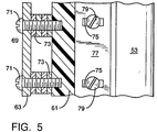
- FIGURE 5 is an elevational view, partly in cross-section, of a portion of the hollow backwash conduit, scraper blade and extension member shown in Figure 4.
- Referring now to the drawings, a self-
cleaning strainer 1 of the present invention is illustrated, the strainer having a vertically disposedhousing 3 which has anupstanding side wall 5, anopen top 7 and abottom wall 9. A flush discharge opening 11 and abackwash discharge opening 13 are provided in thebottom wall 9, the flush discharge opening 11 being attachable to a discharge valve (not shown), such as a shear gate valve, and the backwash discharge opening 13 being sealed, such as by a threadedpipe 15, threadably engaged with thebottom wall 9 of thehousing 3, which pipe contains a shut-offvalve 17. Acover plate 19 sealingly closes theopen top 7 of thehousing 3. Aninlet 21 is provided in thehousing side wall 5 adjacent theopen top 7 for charging of liquid containing particulates to thehousing 3, and anoutlet 23 is also provided int heside wall 5 adjacent thebottom wall 9 for discharge from thehousing 3 of clean liquid after particulates have been removed therefrom. Disposed i thehousing 3 is astationary strainer basket 25 which has a cylindricalforaminous side wall 27, anopen top 29, and anopen bottom 31. Theforaminous side wall 27 hasopenings 33 therethrough such that liquid may pass through theside wall 27 while particulates will be removed from the liquid and collected on theinner surface 35 of theside wall 27. Theside wall 27 of thestrainer basket 25 may be formed from a mesh-like material, a perforated sheet material, a series of spaced bars, or other material forming a foraminous side wall for thestationary strainer basket 25. Thestationary strainer basket 25 is provided with anupper seal 37 which co-operates with aflange 39 extending inwardly from theside wall 5, and alower seal 41 which co-operates with aflange 43 extending inwardly from theside wall 5 to form aspacing 45 between theside wall 5 of thehousing 3 and thewall 27 of thestrainer basket 25. In order to assure that no restriction to flow of the liquid through the self-cleaning strainer 1 occurs, the area of thespacing 45 between theside wall 5 of thehousing 3 and the cylindricalforaminous side wall 27 of astrainer basket 25 is preferably greater than the cross-sectional area of the opening of theinlet 21. -
Means 47 are provided for cleaning theinner surface 35 of thestationary strainer basket 25 and comprise ahollow backwash conduit 51 having anouter wall 53 which defines a chamber 55 (Figure 4), thehollow backwash conduit 51 being disposed in thestationary strainer basket 25 adjacent theinner surface 35 thereof. Abackwash discharge section 57 is provided on thehollow backwash conduit 51, thechamber 55 of which communicates with thebackwash discharge opening 13. Thehollow backwash conduit 51 preferably extends the entire height of thestationary strainer basket 25. Apassage 59 is formed through theouter wall 53 of thehollow backwash conduit 51 which preferably faces theinner surface 35 of thestationary strainer basket 25 and preferably extends substantially the length of saidhollow backwash conduit 51 within thestrainer basket 25. - A shear member or
scraper blade 61 is provided on thehollow backwash conduit 51, within thestationary strainer basket 25, on one side of thepassage 59, which is positioned to contact theinner surface 35 of thebasket 25, and scrape particulate material therefrom. The scraper blade is preferably formed from a high-wear, low friction type material, such as an ultra-high molecular weight polymeric material. Anextension member 63, such as a plate, is provided on the other side of thepassage 59, at a position spaced from thescraper blade 61, so as to form achannel 65 therebetween, whichchannel 65 communicates throughpassage 59 with thechamber 55 in thehollow backwash conduit 51. The size of thechannel 65, and thus the volume of flow of backwash water therethrough to thechamber 55 is adjustable by an adjustable securement of at least one of thescraper blade 61 and theextension member 63. For example, a threadedbore 67 may be provided in thescraper blade 61 and an alignedhole 69 through theextension member 63, with abolt 71 passing through thehole 69 and threadedly engaged with thebore 67 to increase or decrease the width of thechannel 65 between thescraper blade 61 and theextension member 63.Spacers 73, such as washers aboutbolts 71 are used to stabilise theextension member 63 relative to thescraper blade 61 and the number and size ofspacers 73 control the width of thechannel 65. - In order to provide adjustability for the
scraper blade 61 relative to thesurface 35, and adjustability relative to theextension member 63, a series of vertically spacedslots 75 are provided in abase 77 of thescraper blade 61, which base is flush with thewall 53 of the hollow backwash conduit, through whichbolts 79 are passed and secured in threadedbores 81 in thewall 53. Loosening and tightening of thebolts 79 enable movement and securement of thescraper blade 61 in a lateral direction. This lateral adjustment also enables adjustment of thescraper blade 61 relative to theinner surface 35 thestrainer basket 25 to adjust the pressure of contact of the blade against the inner surface. - The
hollow backwash conduit 51 is connected to aspoke 81 that is carried by ashaft 83, that is concentrically positioned in thehousing 3, theshaft 83 extending through abearing 85 in thecover 19 of thehousing 3, and rotatable by amotor 87 that is disposed on thehousing 3. - In order to further clean the
inner surface 35 of thewall 27 ofstrainer basket 25, arotatable brush 89 is provided. Therotatable brush 89 has a bristled portion 91, havingbristles 93 thereon, carried by abrush shaft 95 that is dependent from afurther spoke 99 attached to theshaft 83, and adapted to contact theinner surface 35 of theside wall 27. Theshaft 95 of therotatable brush 89 is adjustably secured to the spoke 99 (Figure 3) such as by use of an adjustment screw connection, using anarm 101 attached to thespoke 99, and ascrew 103 which is threadedly secured in abore 105 in thearm 101 to bear against aconnection 107 of theshaft 95 to thespoke 99. - In operation of the self-
cleaning strainer 1, water containing particulates is charged to thehousing 3 throughinlet 21 and flows, as shown by the arrows in Figure 1, downwardly through theopen top 29 of thestrainer basket 25 into thebasket 25. The water is then directed through theopenings 33 in theforaminous side wall 27 of the strainer basket, into thespacing 45, and clean water is discharged from thehousing 3 throughoutlet 23. Particulates removed from the water are collected on theinner surface 35 of theside wall 27 of thestrainer basket 25. Theinner surface 35 of theside wall 27 of thestrainer basket 25 must be periodically cleaned. - Upon opening of the
valve 17 inpipe 15 attached to the backwash discharge opening 13 of thehousing 3, to open flow through thepipe 15 to the outside atmosphere, a reduced pressure is formed in thechamber 55 of thehollow backwash conduit 51 relative to thespacing 45 between thestrainer basket 25 and thewall 5 of thehousing 3, which forces clean water from thespacing 45 back through theopenings 33 in theforaminous side wall 27 of thestrainer basket 25 in a flow pattern opposite that of normal operational flow. By such reversal of the normal flow pattern, particulate material collected on theinner surface 35 of thestrainer basket 25 in a flow pattern opposite that of normal operational flow. By such reversal of the normal flow pattern, particulate material collected on theinner surface 35 of thestrainer basket 25 is removed and carried by water throughchannel 65 andpassage 59, intochamber 55 of thehollow backwash conduit 51 and out of thebackwash discharge conduit 13 for discharge from thestrainer 1, or it may be directed into the bottom section of thehousing 3 from which it is subsequently discharged through theflush discharge opening 11. The rate of flow and amount of backwash water from the strainer may be controlled by adjusting thevalve 17 so as to control the flow of water from thechamber 55 of thehollow backwash conduit 51. With themotor 87 activated, thehollow backwash conduit 51 and thebrush 89 will be moved about the inside periphery of thestrainer basket 25 to clean the entireinner surface 35 of thewall 27. - Cleaning of the self-cleaning stationary basket strainer is effected when desired, usually when a pressure drop is noted between the
inlet 21 andoutlet 23 of thehousing 3, such as a pressure drop of about 34.4 kn/m⁰ (5 pounds per square inch) or more, indicating plugging of theopenings 33 of the cylindricalforaminous sidewall 27 of thestrainer basket 25. The pressure drop may be sensed, for example, by apressure switch 109 contained in aconduit 111 which communicates with both theinlet 21 andoutlet 23. The pressure switch is connected to activate themotor 87 by any conventional means (not shown). When cleaning is desired, an automatic control system such aspressure switch 109 may be used to start themotor 87 which, throughshaft 83, turns thespokes hollow backwash conduit 51 andbrush 89, such that the bristled portion 91 brushes theinner surface 35 of thesidewall 27 of thestrainer basket 25. As thehollow backwash conduit 51 moves, thescraper blade 61 scrapes along theinner surface 35 to shear any fibres or other particulates clogging theopenings 33 while thebrush 89 brushes thesurface 35. Theshaft 83 may havebottom spokes hollow backwash conduit 51 andbrush shaft 95 for stability, and may also be welded to thebackwash discharge section 57 of the hollow discharge conduit, such as by welds 117 to provide further stability. The particulates scraped from theinner surface 35 by thescraper 61 will flow, with backwash water, through thechannel 65 into thechamber 55 inhollow backwash conduit 51 and be discharged through backwash opening 13, while particulates brushed from thesurface 35 will fall through theopen bottom 31 of thestrainer basket 25 for discharge throughflush discharge opening 11. The flush discharge opening 11 may be open to an off-take continuously or a shear gate valve may be used to close the same when desired. If more flushing of the strainer basket and flush discharge opening 11 is desired, flush water may be charged through a flush water conduit (not shown) downwardly through thestrainer basket 25. When thestrainer basket 25 has been cleaned, themotor 87 is shut down and the rotation of thehollow backwash conduit 51 andbrush 89 is terminated. The self-cleaning strainer may then be used to clean further particulate-laden water. - A cleaning operation may also be effected without interruption of service of the strainer by simply opening a shear gate valve attached to the
flush discharge opening 11. - Also, the strainer may be cleaned by temporarily taking the strainer out of service by closing a valve in a conduit leading to
inlet 21, as well as a valve in a conduit leading fromoutlet 23 and then opening a shear gate valve attached to theflush discharge opening 11. Flush water is then charged through a flush water conduit downwardly through thestrainer basket 25 which will flush out debris through theflush discharge opening 11. - The cleaning of the strainer can be effected, as above-described by use of a pressure drop activated device, by a time activated device to periodically flush out the strainer, or by a device responding to any other preferred electrical or other signal.
- A control panel may be provided that co-operates with the strainer and can be programmed for any type of flushing and in response to any desired signal, so that the user has great flexibility with respect to flushing procedures and the reason for a flushing cycle. Also, the allowable time for flushing can be pre-established and programmed into a control panel. Such a programmer is not necessary to any of the above cleaning procedures, since a user may tie it into the user's own system or effect such a cleaning procedure manually or semi-automatically. Use of such a control panel, however, allows for programming and automatic cleaning to suit a particular installation.
- The preferred embodiment of the present invention provides a self-cleaning strainer having a stationary strainer basket therein with a backwash system for easily cleaning the wall of the strainer basket of particulate material collected on the wall.
- The preferred embodiment of the present invention provides a self-cleaning strainer having a stationary strainer basket therein and a rotatable cleaning device supported for rotation within the strainer basket to clean away particulates collected on the inner surface of the wall of the strainer basket. The pressure within the confines of the
strainer basket 25 and in thespacing 45 between thestrainer basket 25 and thewall 5 of thehousing 3 is increased due to forcing of the water therethrough. - The features disclosed in the foregoing description, in the following Claims and/or in the accompanying drawings may, both separately and in any combination thereof, be material for realising the invention in diverse forms thereof.
Claims (10)
- A self-cleaning stationary basket strainer comprising a vertically disposed housing(3) having an upstanding side wall(5), and open top(7) and a bottom wall(9), with an inlet(21) in the side wall for liquid containing particulates adjacent said open top, an outlet(23) in the side wall adjacent said bottom wall for discharge of clean liquid therefrom, a flush discharge opening(11) in said bottom wall, and a cover plate(19) sealingly closing the open top thereof, a stationary strainer basket(25), having a cylindrical foraminous side wall(27) with an inner surface(35) and an open top(29) and bottom(31), with openings through said cylindrical foraminous side wall for flow of liquid therethrough, disposed in said housing(3), spaced from said side wall(5) of said housing and disposed below said inlet(21), such that liquid containing particulates entering through said inlet passes into the strainer basket and outwardly through said openings to remove said particulates, and clean liquid is directed through said outlet, means(47) for cleaning the inner surface of said strainer basket to remove particulates collected thereon, adapted to move about the inner periphery of said stationary strainer basket, including a hollow backwash conduit(51) having an outer wall(53) defining a chamber(35), disposed in said stationary strainer basket(25) adjacent the inner surface thereof(35), said hollow backwash conduit(51) having a passage(59) through the outer wall thereof facing said inner surface, a backwash discharge opening(13) in a wall of said housing, a backwash discharge section(52) on said backwash conduit(51) communicating with said backwash discharge opening(13), and means(17) for closing and opening said backwash discharge opening.
- A self-cleaning stationary basket strainer as defined in Claim 1 wherein said passage(59) through the outer wall of said hollow backwash conduit(51) extends substantially the length of said conduit within said stationary strainer basket(25).
- A self-cleaning stationary basket strainer as defined in Claim 1 or 2 including means(17) for regulating the volume of flow of said backwash water through said hollow backwash conduit(51).
- A self-cleaning stationary basket strainer as defined in any one of the preceding Claims including a scraper blade(61) on one side of said passage on said hollow backwash conduit(51), positioned to contact said inner surface(35).
- A self-cleaning stationary basket strainer as defined in Claim 4 comprising an extension member(63) on the other side of said passage on said backwash conduit extending towards said inner surface, said scraper blade(61) and extension member(63) being spaced from each other to form a channel(65) therebetween communicating through said passage(59) with the chamber(55) of said hollow backwash conduit(51).
- A self-cleaning stationary basket strainer as defined in Claim 5 wherein at least one of said scraper blade(61) and said extension member(63) is adjustably secured relative to the other so as to enable adjustment of the width of said channel.
- A self-cleaning stationary basket strainer as defined in Claim 4, 5 or 6 including means(75,79) for varying the pressure of contact of said scraper blade on said inner surface.
- A self-cleaning stationary basket strainer as defined in any one of the preceding Claims wherein the cleaning means(47) include a rotatable bristled brush(89) adapted to move about the inner periphery of said stationary strainer basket(25), positioned such that the bristles on the brush contact said inner surface(35).
- A self-cleaning stationary basket strainer as defined in Claim 8 wherein means(87) are provided for intermittently rotating the brush.
- A self-cleaning stationary basket strainer according to any one of the preceding Claims wherein the cleaning means(47) are mounted on a shaft(83) so as to be rotatable within the basket(25).
Applications Claiming Priority (2)
| Application Number | Priority Date | Filing Date | Title |
|---|---|---|---|
| US07/908,978 US5401396A (en) | 1991-08-22 | 1992-07-06 | Self-cleaning stationary basket strainer |
| US908978 | 1992-07-06 |
Publications (2)
| Publication Number | Publication Date |
|---|---|
| EP0578003A1 true EP0578003A1 (en) | 1994-01-12 |
| EP0578003B1 EP0578003B1 (en) | 1996-08-14 |
Family
ID=25426460
Family Applications (1)
| Application Number | Title | Priority Date | Filing Date |
|---|---|---|---|
| EP93109476A Expired - Lifetime EP0578003B1 (en) | 1992-07-06 | 1993-06-14 | A self-cleaning stationary basket strainer |
Country Status (7)
| Country | Link |
|---|---|
| US (1) | US5401396A (en) |
| EP (1) | EP0578003B1 (en) |
| JP (1) | JPH0679111A (en) |
| AT (1) | ATE141179T1 (en) |
| CA (1) | CA2098443C (en) |
| DE (1) | DE69303997T2 (en) |
| ES (1) | ES2091522T3 (en) |
Cited By (4)
| Publication number | Priority date | Publication date | Assignee | Title |
|---|---|---|---|---|
| ES2190714A1 (en) * | 2000-12-05 | 2003-08-01 | Fernandez Cristobal Lozano | Improved food mixing and grinding machine |
| GB2388797A (en) * | 2002-03-25 | 2003-11-26 | Son Screen Pty Ltd | An overflow screening device including an internal brush arrangement |
| EP2767321A1 (en) * | 2013-02-13 | 2014-08-20 | F.M., S.r.L. Unipersonale | Self-cleaning filter |
| CN104689618A (en) * | 2013-12-04 | 2015-06-10 | 宁安市粮油淀粉机械制造有限公司 | Rotary starch filter |
Families Citing this family (46)
| Publication number | Priority date | Publication date | Assignee | Title |
|---|---|---|---|---|
| US5443726A (en) * | 1993-10-13 | 1995-08-22 | Tm Industrial Supply, Inc. | Self-cleaning filter assembly |
| FR2743505B1 (en) * | 1996-01-15 | 1998-02-13 | Cellier Groupe Sa | SELF-CLEANING FILTRATION DEVICE |
| US5993652A (en) * | 1998-06-17 | 1999-11-30 | Perfection Sprinkler Co. | Self-cleaning strainer having rotating strainer frame assembly journaled on central core by sets of wheels |
| US6162357A (en) * | 1998-09-21 | 2000-12-19 | Boston Bay International, Inc. | Magnetic filter-separator having rotatable helical rods |
| US6402948B1 (en) * | 2000-04-21 | 2002-06-11 | Phoenix Environmental Assets Corp. | Filter-separator for purifying liquid hydrocarbons |
| US6575307B2 (en) | 2000-10-10 | 2003-06-10 | Rain Bird Corporation | Self-cleaning water filter |
| EP1361913A1 (en) * | 2001-01-18 | 2003-11-19 | Nicholas Jackson | Water filter |
| US6758344B2 (en) | 2002-02-21 | 2004-07-06 | Gordon Construction, Inc. | Self-cleaning fluid filter system |
| EP1485181B1 (en) * | 2002-02-21 | 2007-09-12 | Gordon Construction, Inc. | Self-cleaning fluid filter system |
| US6848584B2 (en) * | 2002-09-26 | 2005-02-01 | Drilltec Patents & Technologies Co., Inc. | Strainer basket and method of making and using the same |
| DE10252194A1 (en) * | 2002-11-09 | 2004-05-27 | Hilti Ag | Portable drilling water filter with self-cleaning |
| US7083735B2 (en) * | 2003-09-03 | 2006-08-01 | Laing David A | High debris content strainer |
| US7347933B2 (en) * | 2003-11-17 | 2008-03-25 | Intake Screens, Inc. | Self-cleaning intake screen |
| US20050199551A1 (en) * | 2004-03-10 | 2005-09-15 | Gordon Robert R. | Method and system for filtering sediment-bearing fluids |
| US20070187328A1 (en) * | 2004-03-10 | 2007-08-16 | Gordon Robert R | Method and system for filtering sediment-bearing fluids |
| US7468082B2 (en) * | 2004-04-28 | 2008-12-23 | Gordon Robert R | Self cleaning gas filtering system and method |
| KR100538306B1 (en) * | 2004-09-30 | 2005-12-23 | 김성철 | Self-cleaning filtering system |
| US7533693B2 (en) * | 2005-10-31 | 2009-05-19 | Ga Industries, Llc | Side-mounted position indicator for flapper check valve |
| US7364662B2 (en) * | 2005-11-22 | 2008-04-29 | Laing David A | Scraper adjustment mechanism and method |
| KR100752593B1 (en) * | 2006-02-08 | 2007-08-29 | 주식회사 카타딘 아시아 | Filter Housing Assembly for Water Conditioner Having Self-Cleaner |
| ITRE20060114A1 (en) * | 2006-09-28 | 2008-03-29 | P M P O S R L | FILTRATION AND COMPACTING DEVICE FOR SUSPENDED SOLID PARTICLES AND CONTAINED IN FLUIDS, LIKE MECHANICAL WORKING SLUDGE |
| US8505566B2 (en) | 2007-10-17 | 2013-08-13 | The Toro Company | Valve glue diverter |
| US8360250B2 (en) * | 2007-12-07 | 2013-01-29 | The Toro Company | Self-cleaning valve |
| KR101381042B1 (en) * | 2008-07-16 | 2014-04-04 | 가부시키가이샤 호리바 세이사꾸쇼 | Particulate Matter Measurement Device |
| US9409106B2 (en) | 2010-03-12 | 2016-08-09 | Spiral Water Technologies, Inc. | Fluid filtration and particle concentration device and methods |
| US8740177B2 (en) | 2011-07-05 | 2014-06-03 | Rain Bird Corporation | Eccentric diaphragm valve |
| US8945379B2 (en) | 2011-12-30 | 2015-02-03 | James Gregory Brull | Strainer for pump |
| US8372281B1 (en) | 2012-01-31 | 2013-02-12 | Industrial Manufacturing Company | Scraper adjustment mechanism and method |
| CN102716608B (en) * | 2012-06-08 | 2014-12-10 | 温州宇丰化纤机械有限公司 | Automatic back washing carbon fiber filter |
| US9561454B2 (en) * | 2012-10-09 | 2017-02-07 | Ovivo Inc. | Debris filter with splitter bar |
| US20140116965A1 (en) * | 2012-11-01 | 2014-05-01 | Machinerie Agricole Bois-Francs Inc. | Separator and method for separating a heterogeneous supply |
| ES2661731T3 (en) * | 2013-09-12 | 2018-04-03 | Antel Aritma Tesisleri Insaat Sanay Ve Ticaret Anonimim Sirketi | Automatic brush and nozzle cleaning filter with gearmotor |
| CN105745001B (en) * | 2013-10-29 | 2017-04-05 | 现代重工业株式会社 | Backwashing fluid drainage arrangement and defecator |
| US9539674B2 (en) | 2013-11-22 | 2017-01-10 | Rain Bird Corporation | Clog resistant valve port and methods relating to same |
| US10286338B2 (en) | 2014-01-13 | 2019-05-14 | Spiral Water Technologies, Inc. | Flow control features for fluid filtration device and methods |
| US10245531B2 (en) * | 2015-06-17 | 2019-04-02 | Tm Industrial Supply, Inc. | High-efficiency automatic self-cleaning strainer |
| US10286339B2 (en) * | 2015-11-16 | 2019-05-14 | Halliburton Energy Services, Inc. | Filter screen brush assembly |
| CN108079640A (en) * | 2017-12-15 | 2018-05-29 | 宜兴市江华环保科技有限公司 | A kind of fully-automatic intelligent water filter |
| CN108043100A (en) * | 2017-12-25 | 2018-05-18 | 中信环境技术(广州)有限公司 | A kind of preposition pretreatment system for sewage of membrane bioreactor |
| CN111225728B (en) * | 2018-05-15 | 2022-04-05 | 株式会社荒井铁工所 | Shearing member and filtering device |
| CN108854196B (en) * | 2018-07-09 | 2021-05-18 | 徐州虹源环保科技有限公司 | Water guide box for environment-friendly sewage treatment tank |
| CN110227290A (en) * | 2019-06-17 | 2019-09-13 | 南京宏匡硅材料有限公司 | Filter is used in a kind of production of silane coupling agent |
| US10751648B1 (en) * | 2019-08-09 | 2020-08-25 | Durwood Nelson Renfrow | Apparatus and system for removing liquid from slurry |
| CN112999728A (en) * | 2021-02-26 | 2021-06-22 | 贵州高原绿光蜜蜂蜂业有限公司 | Filtering device for bee breeding |
| IT202100012296A1 (en) * | 2021-05-13 | 2022-11-13 | Elfi S R L | FILTER TO RETAIN, OR WITHHOLD, CORRESPONDING RESIDUES OR SOLID PARTICLES WHICH ARE CONTAINED IN A CORRESPONDING FLUID TO BE FILTERED |
| CN116835762B (en) * | 2023-07-25 | 2024-01-09 | 江苏金山新材料科技有限公司 | Anti-blocking feeding equipment for carbon source for sewage treatment and application method of anti-blocking feeding equipment |
Citations (3)
| Publication number | Priority date | Publication date | Assignee | Title |
|---|---|---|---|---|
| FR1332661A (en) * | 1962-05-25 | 1963-07-19 | Continuous flow filter and automatic hydraulic unclogging | |
| GB2157964A (en) * | 1984-04-26 | 1985-11-06 | Swinney Eng | Backwash filter |
| EP0531747A1 (en) * | 1991-08-22 | 1993-03-17 | Ga Industries, Inc. | A self-cleaning strainer |
Family Cites Families (14)
| Publication number | Priority date | Publication date | Assignee | Title |
|---|---|---|---|---|
| US2275958A (en) * | 1939-03-17 | 1942-03-10 | Eugene A Hagel | Fluid strainer |
| US3574509A (en) * | 1969-02-14 | 1971-04-13 | Zurn Ind Inc | Backwash filter |
| JPS4886165A (en) * | 1972-02-17 | 1973-11-14 | ||
| JPS52131669A (en) * | 1976-04-28 | 1977-11-04 | Mitsubishi Electric Corp | Discharge lamp lighting device |
| FR2424053A1 (en) * | 1978-04-27 | 1979-11-23 | Lecoeur Roger | Horizontal rotary screening drum to filter flocculated waste water - with screw press continuously removing filter cake from drum interior |
| US4315820A (en) * | 1980-01-23 | 1982-02-16 | Zurn Industries, Inc. | Self-cleaning strainer |
| CH653570A5 (en) * | 1983-06-30 | 1986-01-15 | Rehman Process Eng | PRESSURE REACTOR. |
| IL71999A0 (en) * | 1984-06-04 | 1984-10-31 | Filtration Water Filters For A | Fluid filter system and suction nozzle therefor |
| EP0253006B1 (en) * | 1986-07-15 | 1989-05-31 | Hermann Finckh Maschinenfabrik GmbH & Co. | Pressure separator |
| US4818402A (en) * | 1987-08-17 | 1989-04-04 | Tm Industrial Supply, Inc. | Self cleaning strainer |
| JPH0759287B2 (en) * | 1989-05-29 | 1995-06-28 | ダイハツデイーゼル株式会社 | Washing filter |
| DE4042167A1 (en) * | 1989-12-29 | 1991-07-11 | Huber Hans Georg | Device for removing undesirable material from water in sewage works - including inclined screw conveyor with internal ribs on screw housing and spray nozzles for washing material |
| US5152891A (en) * | 1990-09-13 | 1992-10-06 | T/M Industrial Supply, Inc. | Self-cleaning strainer |
| US5183568A (en) * | 1991-08-22 | 1993-02-02 | G A Industries, Inc. | Self-cleaning strainer |
-
1992
- 1992-07-06 US US07/908,978 patent/US5401396A/en not_active Expired - Fee Related
-
1993
- 1993-06-14 DE DE69303997T patent/DE69303997T2/en not_active Expired - Fee Related
- 1993-06-14 ES ES93109476T patent/ES2091522T3/en not_active Expired - Lifetime
- 1993-06-14 EP EP93109476A patent/EP0578003B1/en not_active Expired - Lifetime
- 1993-06-14 AT AT93109476T patent/ATE141179T1/en active
- 1993-06-15 CA CA002098443A patent/CA2098443C/en not_active Expired - Fee Related
- 1993-07-05 JP JP5165551A patent/JPH0679111A/en active Pending
Patent Citations (3)
| Publication number | Priority date | Publication date | Assignee | Title |
|---|---|---|---|---|
| FR1332661A (en) * | 1962-05-25 | 1963-07-19 | Continuous flow filter and automatic hydraulic unclogging | |
| GB2157964A (en) * | 1984-04-26 | 1985-11-06 | Swinney Eng | Backwash filter |
| EP0531747A1 (en) * | 1991-08-22 | 1993-03-17 | Ga Industries, Inc. | A self-cleaning strainer |
Cited By (5)
| Publication number | Priority date | Publication date | Assignee | Title |
|---|---|---|---|---|
| ES2190714A1 (en) * | 2000-12-05 | 2003-08-01 | Fernandez Cristobal Lozano | Improved food mixing and grinding machine |
| GB2388797A (en) * | 2002-03-25 | 2003-11-26 | Son Screen Pty Ltd | An overflow screening device including an internal brush arrangement |
| GB2388797B (en) * | 2002-03-25 | 2005-07-20 | Son Screen Pty Ltd | Overflow screening device |
| EP2767321A1 (en) * | 2013-02-13 | 2014-08-20 | F.M., S.r.L. Unipersonale | Self-cleaning filter |
| CN104689618A (en) * | 2013-12-04 | 2015-06-10 | 宁安市粮油淀粉机械制造有限公司 | Rotary starch filter |
Also Published As
| Publication number | Publication date |
|---|---|
| EP0578003B1 (en) | 1996-08-14 |
| JPH0679111A (en) | 1994-03-22 |
| CA2098443A1 (en) | 1994-01-07 |
| DE69303997T2 (en) | 1996-12-19 |
| ATE141179T1 (en) | 1996-08-15 |
| US5401396A (en) | 1995-03-28 |
| ES2091522T3 (en) | 1996-11-01 |
| DE69303997D1 (en) | 1996-09-19 |
| CA2098443C (en) | 1999-03-23 |
Similar Documents
| Publication | Publication Date | Title |
|---|---|---|
| EP0578003B1 (en) | A self-cleaning stationary basket strainer | |
| US5370791A (en) | Backwashable self-cleaning strainer | |
| US5183568A (en) | Self-cleaning strainer | |
| US20020008068A1 (en) | Apparatus and method for backwashing fluid filter systems | |
| EP0494800B1 (en) | Filter with reciprocating cleaner unit | |
| US5595655A (en) | Self-cleaning filter assembly | |
| US3979289A (en) | Filtration method | |
| US5129758A (en) | System and method for distribution of greywater to a soil bed | |
| EP0375739B1 (en) | Water clarification system adapted for removing particulate matter of greater than a predetermined size | |
| US10792595B2 (en) | Drum filter for water filtration and method therefor | |
| KR20130128602A (en) | Filtering apparatus | |
| US6475377B1 (en) | Media vacuum filter | |
| US20090026152A1 (en) | Modular filter and vacuum head assembly for a filtering apparatus | |
| KR100564250B1 (en) | Drum screen type wastewater treatment apparatus | |
| KR100414905B1 (en) | Cylindrical fine solid material eliminator for sewage and waste water | |
| US20200391144A1 (en) | Filter unit and filtration system | |
| KR100808905B1 (en) | Apparatus for filteration of water | |
| KR20020084663A (en) | Auto clean filter | |
| JPS61263613A (en) | Automatic flushing filter | |
| JPH04227006A (en) | Filter and its application | |
| CN219002283U (en) | Sewage centralized treatment equipment | |
| KR100443586B1 (en) | Rotate type filtering equipment | |
| AU5493896A (en) | Apparatus and method for backwashing fluid filter systems | |
| SU1595404A1 (en) | Sprinkling machine water intake | |
| IL272438B2 (en) | Self-cleaning filtering system and method |
Legal Events
| Date | Code | Title | Description |
|---|---|---|---|
| PUAI | Public reference made under article 153(3) epc to a published international application that has entered the european phase |
Free format text: ORIGINAL CODE: 0009012 |
|
| AK | Designated contracting states |
Kind code of ref document: A1 Designated state(s): AT BE CH DE DK ES FR GB GR IE IT LI LU NL PT SE |
|
| 17P | Request for examination filed |
Effective date: 19940321 |
|
| 17Q | First examination report despatched |
Effective date: 19950421 |
|
| GRAH | Despatch of communication of intention to grant a patent |
Free format text: ORIGINAL CODE: EPIDOS IGRA |
|
| GRAH | Despatch of communication of intention to grant a patent |
Free format text: ORIGINAL CODE: EPIDOS IGRA |
|
| GRAA | (expected) grant |
Free format text: ORIGINAL CODE: 0009210 |
|
| AK | Designated contracting states |
Kind code of ref document: B1 Designated state(s): AT BE CH DE DK ES FR GB GR IE IT LI LU NL PT SE |
|
| PG25 | Lapsed in a contracting state [announced via postgrant information from national office to epo] |
Ref country code: GR Free format text: LAPSE BECAUSE OF FAILURE TO SUBMIT A TRANSLATION OF THE DESCRIPTION OR TO PAY THE FEE WITHIN THE PRESCRIBED TIME-LIMIT Effective date: 19960814 Ref country code: FR Effective date: 19960814 Ref country code: DK Effective date: 19960814 Ref country code: BE Effective date: 19960814 Ref country code: AT Effective date: 19960814 |
|
| REF | Corresponds to: |
Ref document number: 141179 Country of ref document: AT Date of ref document: 19960815 Kind code of ref document: T |
|
| ITF | It: translation for a ep patent filed |
Owner name: DR. ING. A. RACHELI & C. |
|
| REG | Reference to a national code |
Ref country code: IE Ref legal event code: FG4D Free format text: 69423 |
|
| REF | Corresponds to: |
Ref document number: 69303997 Country of ref document: DE Date of ref document: 19960919 |
|
| REG | Reference to a national code |
Ref country code: CH Ref legal event code: NV Representative=s name: BOVARD AG PATENTANWAELTE |
|
| REG | Reference to a national code |
Ref country code: ES Ref legal event code: FG2A Ref document number: 2091522 Country of ref document: ES Kind code of ref document: T3 |
|
| PG25 | Lapsed in a contracting state [announced via postgrant information from national office to epo] |
Ref country code: SE Effective date: 19961114 Ref country code: PT Effective date: 19961114 |
|
| EN | Fr: translation not filed | ||
| PLBE | No opposition filed within time limit |
Free format text: ORIGINAL CODE: 0009261 |
|
| STAA | Information on the status of an ep patent application or granted ep patent |
Free format text: STATUS: NO OPPOSITION FILED WITHIN TIME LIMIT |
|
| PG25 | Lapsed in a contracting state [announced via postgrant information from national office to epo] |
Ref country code: LU Free format text: LAPSE BECAUSE OF NON-PAYMENT OF DUE FEES Effective date: 19970630 |
|
| 26N | No opposition filed | ||
| REG | Reference to a national code |
Ref country code: GB Ref legal event code: IF02 |
|
| PGFP | Annual fee paid to national office [announced via postgrant information from national office to epo] |
Ref country code: GB Payment date: 20020612 Year of fee payment: 10 |
|
| PGFP | Annual fee paid to national office [announced via postgrant information from national office to epo] |
Ref country code: CH Payment date: 20020617 Year of fee payment: 10 |
|
| PGFP | Annual fee paid to national office [announced via postgrant information from national office to epo] |
Ref country code: ES Payment date: 20020618 Year of fee payment: 10 |
|
| PGFP | Annual fee paid to national office [announced via postgrant information from national office to epo] |
Ref country code: DE Payment date: 20020619 Year of fee payment: 10 |
|
| PGFP | Annual fee paid to national office [announced via postgrant information from national office to epo] |
Ref country code: IE Payment date: 20020625 Year of fee payment: 10 |
|
| PGFP | Annual fee paid to national office [announced via postgrant information from national office to epo] |
Ref country code: NL Payment date: 20020628 Year of fee payment: 10 |
|
| PG25 | Lapsed in a contracting state [announced via postgrant information from national office to epo] |
Ref country code: GB Free format text: LAPSE BECAUSE OF NON-PAYMENT OF DUE FEES Effective date: 20030614 |
|
| PG25 | Lapsed in a contracting state [announced via postgrant information from national office to epo] |
Ref country code: IE Free format text: LAPSE BECAUSE OF NON-PAYMENT OF DUE FEES Effective date: 20030616 Ref country code: ES Free format text: LAPSE BECAUSE OF NON-PAYMENT OF DUE FEES Effective date: 20030616 |
|
| PG25 | Lapsed in a contracting state [announced via postgrant information from national office to epo] |
Ref country code: LI Free format text: LAPSE BECAUSE OF NON-PAYMENT OF DUE FEES Effective date: 20030630 Ref country code: CH Free format text: LAPSE BECAUSE OF NON-PAYMENT OF DUE FEES Effective date: 20030630 |
|
| PG25 | Lapsed in a contracting state [announced via postgrant information from national office to epo] |
Ref country code: NL Free format text: LAPSE BECAUSE OF NON-PAYMENT OF DUE FEES Effective date: 20040101 Ref country code: DE Free format text: LAPSE BECAUSE OF NON-PAYMENT OF DUE FEES Effective date: 20040101 |
|
| GBPC | Gb: european patent ceased through non-payment of renewal fee |
Effective date: 20030614 |
|
| REG | Reference to a national code |
Ref country code: CH Ref legal event code: PL |
|
| NLV4 | Nl: lapsed or anulled due to non-payment of the annual fee |
Effective date: 20040101 |
|
| REG | Reference to a national code |
Ref country code: IE Ref legal event code: MM4A |
|
| REG | Reference to a national code |
Ref country code: ES Ref legal event code: FD2A Effective date: 20030616 |
|
| PG25 | Lapsed in a contracting state [announced via postgrant information from national office to epo] |
Ref country code: IT Free format text: LAPSE BECAUSE OF NON-PAYMENT OF DUE FEES Effective date: 20050614 |