EP0577388B1 - Material handling machine - Google Patents
Material handling machine Download PDFInfo
- Publication number
- EP0577388B1 EP0577388B1 EP93305075A EP93305075A EP0577388B1 EP 0577388 B1 EP0577388 B1 EP 0577388B1 EP 93305075 A EP93305075 A EP 93305075A EP 93305075 A EP93305075 A EP 93305075A EP 0577388 B1 EP0577388 B1 EP 0577388B1
- Authority
- EP
- European Patent Office
- Prior art keywords
- machine
- chassis
- cab
- axle
- material handling
- Prior art date
- Legal status (The legal status is an assumption and is not a legal conclusion. Google has not performed a legal analysis and makes no representation as to the accuracy of the status listed.)
- Expired - Lifetime
Links
Images


Classifications
-
- E—FIXED CONSTRUCTIONS
- E02—HYDRAULIC ENGINEERING; FOUNDATIONS; SOIL SHIFTING
- E02F—DREDGING; SOIL-SHIFTING
- E02F9/00—Component parts of dredgers or soil-shifting machines, not restricted to one of the kinds covered by groups E02F3/00 - E02F7/00
- E02F9/08—Superstructures; Supports for superstructures
- E02F9/0858—Arrangement of component parts installed on superstructures not otherwise provided for, e.g. electric components, fenders, air-conditioning units
- E02F9/0866—Engine compartment, e.g. heat exchangers, exhaust filters, cooling devices, silencers, mufflers, position of hydraulic pumps in the engine compartment
-
- B—PERFORMING OPERATIONS; TRANSPORTING
- B60—VEHICLES IN GENERAL
- B60K—ARRANGEMENT OR MOUNTING OF PROPULSION UNITS OR OF TRANSMISSIONS IN VEHICLES; ARRANGEMENT OR MOUNTING OF PLURAL DIVERSE PRIME-MOVERS IN VEHICLES; AUXILIARY DRIVES FOR VEHICLES; INSTRUMENTATION OR DASHBOARDS FOR VEHICLES; ARRANGEMENTS IN CONNECTION WITH COOLING, AIR INTAKE, GAS EXHAUST OR FUEL SUPPLY OF PROPULSION UNITS IN VEHICLES
- B60K17/00—Arrangement or mounting of transmissions in vehicles
- B60K17/34—Arrangement or mounting of transmissions in vehicles for driving both front and rear wheels, e.g. four wheel drive vehicles
-
- B—PERFORMING OPERATIONS; TRANSPORTING
- B62—LAND VEHICLES FOR TRAVELLING OTHERWISE THAN ON RAILS
- B62D—MOTOR VEHICLES; TRAILERS
- B62D21/00—Understructures, i.e. chassis frame on which a vehicle body may be mounted
- B62D21/18—Understructures, i.e. chassis frame on which a vehicle body may be mounted characterised by the vehicle type and not provided for in groups B62D21/02 - B62D21/17
- B62D21/186—Understructures, i.e. chassis frame on which a vehicle body may be mounted characterised by the vehicle type and not provided for in groups B62D21/02 - B62D21/17 for building site vehicles or multi-purpose tractors
-
- B—PERFORMING OPERATIONS; TRANSPORTING
- B66—HOISTING; LIFTING; HAULING
- B66F—HOISTING, LIFTING, HAULING OR PUSHING, NOT OTHERWISE PROVIDED FOR, e.g. DEVICES WHICH APPLY A LIFTING OR PUSHING FORCE DIRECTLY TO THE SURFACE OF A LOAD
- B66F9/00—Devices for lifting or lowering bulky or heavy goods for loading or unloading purposes
- B66F9/06—Devices for lifting or lowering bulky or heavy goods for loading or unloading purposes movable, with their loads, on wheels or the like, e.g. fork-lift trucks
- B66F9/065—Devices for lifting or lowering bulky or heavy goods for loading or unloading purposes movable, with their loads, on wheels or the like, e.g. fork-lift trucks non-masted
- B66F9/0655—Devices for lifting or lowering bulky or heavy goods for loading or unloading purposes movable, with their loads, on wheels or the like, e.g. fork-lift trucks non-masted with a telescopic boom
-
- E—FIXED CONSTRUCTIONS
- E02—HYDRAULIC ENGINEERING; FOUNDATIONS; SOIL SHIFTING
- E02F—DREDGING; SOIL-SHIFTING
- E02F3/00—Dredgers; Soil-shifting machines
- E02F3/04—Dredgers; Soil-shifting machines mechanically-driven
- E02F3/28—Dredgers; Soil-shifting machines mechanically-driven with digging tools mounted on a dipper- or bucket-arm, i.e. there is either one arm or a pair of arms, e.g. dippers, buckets
- E02F3/283—Dredgers; Soil-shifting machines mechanically-driven with digging tools mounted on a dipper- or bucket-arm, i.e. there is either one arm or a pair of arms, e.g. dippers, buckets with a single arm pivoted directly on the chassis
- E02F3/286—Dredgers; Soil-shifting machines mechanically-driven with digging tools mounted on a dipper- or bucket-arm, i.e. there is either one arm or a pair of arms, e.g. dippers, buckets with a single arm pivoted directly on the chassis telescopic or slidable
-
- E—FIXED CONSTRUCTIONS
- E02—HYDRAULIC ENGINEERING; FOUNDATIONS; SOIL SHIFTING
- E02F—DREDGING; SOIL-SHIFTING
- E02F3/00—Dredgers; Soil-shifting machines
- E02F3/04—Dredgers; Soil-shifting machines mechanically-driven
- E02F3/96—Dredgers; Soil-shifting machines mechanically-driven with arrangements for alternate or simultaneous use of different digging elements
- E02F3/963—Arrangements on backhoes for alternate use of different tools
- E02F3/964—Arrangements on backhoes for alternate use of different tools of several tools mounted on one machine
-
- E—FIXED CONSTRUCTIONS
- E02—HYDRAULIC ENGINEERING; FOUNDATIONS; SOIL SHIFTING
- E02F—DREDGING; SOIL-SHIFTING
- E02F9/00—Component parts of dredgers or soil-shifting machines, not restricted to one of the kinds covered by groups E02F3/00 - E02F7/00
- E02F9/02—Travelling-gear, e.g. associated with slewing gears
- E02F9/028—Travelling-gear, e.g. associated with slewing gears with arrangements for levelling the machine
-
- E—FIXED CONSTRUCTIONS
- E02—HYDRAULIC ENGINEERING; FOUNDATIONS; SOIL SHIFTING
- E02F—DREDGING; SOIL-SHIFTING
- E02F9/00—Component parts of dredgers or soil-shifting machines, not restricted to one of the kinds covered by groups E02F3/00 - E02F7/00
- E02F9/08—Superstructures; Supports for superstructures
- E02F9/0808—Improving mounting or assembling, e.g. frame elements, disposition of all the components on the superstructures
-
- E—FIXED CONSTRUCTIONS
- E02—HYDRAULIC ENGINEERING; FOUNDATIONS; SOIL SHIFTING
- E02F—DREDGING; SOIL-SHIFTING
- E02F9/00—Component parts of dredgers or soil-shifting machines, not restricted to one of the kinds covered by groups E02F3/00 - E02F7/00
- E02F9/08—Superstructures; Supports for superstructures
- E02F9/085—Ground-engaging fitting for supporting the machines while working, e.g. outriggers, legs
-
- E—FIXED CONSTRUCTIONS
- E02—HYDRAULIC ENGINEERING; FOUNDATIONS; SOIL SHIFTING
- E02F—DREDGING; SOIL-SHIFTING
- E02F9/00—Component parts of dredgers or soil-shifting machines, not restricted to one of the kinds covered by groups E02F3/00 - E02F7/00
- E02F9/16—Cabins, platforms, or the like, for drivers
- E02F9/166—Cabins, platforms, or the like, for drivers movable, tiltable or pivoting, e.g. movable seats, dampening arrangements of cabins
-
- E—FIXED CONSTRUCTIONS
- E02—HYDRAULIC ENGINEERING; FOUNDATIONS; SOIL SHIFTING
- E02F—DREDGING; SOIL-SHIFTING
- E02F9/00—Component parts of dredgers or soil-shifting machines, not restricted to one of the kinds covered by groups E02F3/00 - E02F7/00
- E02F9/20—Drives; Control devices
- E02F9/22—Hydraulic or pneumatic drives
- E02F9/2257—Vehicle levelling or suspension systems
-
- B—PERFORMING OPERATIONS; TRANSPORTING
- B60—VEHICLES IN GENERAL
- B60G—VEHICLE SUSPENSION ARRANGEMENTS
- B60G2300/00—Indexing codes relating to the type of vehicle
- B60G2300/09—Construction vehicles, e.g. graders, excavators
Definitions
- This invention relates to machines for handling materials, in particular machines which can be used for loading or digging.
- Material handling machines for use on construction sites usually have crawler tracks or large-diameter wheels and are usually designed to carry out a given task such as digging, loading, or pallet-lifting. If a machine is designed to carry out two tasks, one of these will be the primary task, and the secondary task will be carried out less efficiently, because of physical design constraints.
- an engine mounted at an arbitrary position on the chassis usually drives a hydraulic pump which supplies a hydraulic circuit feeding hydraulic motors associated with the wheels.
- a hydraulic transmission is very inefficient compared with a mechanical transmission.
- One known machine which is in use has a rear-mounted backhoe, a front-mounted engine, and a front-mounted linkage carrying a loader bucket. This has the disadvantages of poor loader visibility (the operator's line of sight is obstructed by the bonnet of the engine) and poor manoeuvrability (the linkage obstructs the turning of the front wheels).
- a similar known machine improves manoeuvrability by using smaller front wheels, but this compromises stability and load capacity.
- Another known machine has a rear-mounted engine and a front-mounted linkage carrying a loader bucker, pallet forks, or a telescopic arm. Forward visibility is good, but a backhoe has to be omitted because of the rear-mounted engine.
- a telescopic boom extends forwards from a rear pivotal mounting, along the centre-line of the machine, the operator's cab being mounted at one side.
- the extremity of the boom carries a loader bucket or pallet forks. Again, forward visibility is good but a backhoe cannot be fitted at the rear.
- the main problem to be overcome is to locate the essential components (engine, transmission, cab, and loader linkage or boom) in the optimum position, from the mechanical and functional point of view, whilst maintaining good visibility for all functions, stability, manoeuvrability, structural integrity, and ease of servicing.
- CA-A-2009968 discloses a material handling machine comprising: a chassis comprising a rigid longitudinal frame; an operator's cab mounted on the chassis; material handling means pivotally mounted on the chassis; a front axle and a rear axle mounted on the chassis; wheels mounted on the axles; a drive arrangement mounted on the chassis; at one side of the longitudinal frame, between the front and rear axles, the drive arrangement comprising an engine and a mechanically driven transmission kinematically connected to the engine and having a power output substantially mid-way along the drive arrangement; final drive units, and according to the present invention, such a machine is characterised in that the engine has a longitudinal extending median plane which is tilted at an angle of substantially 10° to the vertical, so as to bring an output of the mechanically driven transmission closer to the central plane of the machine.
- the side-mounted engine and transmission can be made readily accessible for servicing.
- the drive arrangement can be mounted on a transverse chassis frame mounted on the longitudinal frame without compromising the structural integrity of the longitudinal frame. It is possible to provide good manoeuvrability of the wheels unrestricted by the drive arrangement.
- the front and rear wheels can be of substantially equal size, giving good stability and load capacity. Stability is also enhanced by a long wheel-base. Adequate height and reach for a wide range of lifting and loading operations can be provided by a boom, which may have one, two, three, or more sections.
- the material handling machine has a chassis for mounting means for carrying out operations in front of and to the rear of the machine, and an operator's cab mounted on the chassis, the cab being mounted for movement between a first position in which the region in front ofthe machine is more easily visible to the operator and a second position in which the region to the rear of the machine is more easily visible.
- first and second positions are forward and rearward positions.
- One of the positions is preferably higher than the other.
- One of the positions may conveniently be substantially mid-way along the chassis.
- the cab may be configured to pivot about a vertical axis during movement between the first and second positions, this may require extra width-wise space and it is preferable for the movement to be one of translation only.
- the cab contains first controls for operations in front of the machine and second controls for operations to the rear of the machine, the first and second controls being respectively at the front and rear of the cab in both of its said positions.
- the cab contains an operator's seat which is rotatable through at least 180° about a vertical axis.
- the material handling machine has a chassis comprising a rigid longitudinal frame, a front axle and a rear axle mounted on the chassis, wheels mounted on the axles, a drive arrangement comprising an engine and a mechanically driven transmission kinematically connected to the engine, the drive arrangement having a power output, final drive units on the respective front and rear axles, for driving the wheels, and shafts kinematically connecting the power output to the final drive units, the drive arrangement being mounted at one side of the longitudinal frame, between the front and rear axles, the power output being substantially mid-way along the drive arrangement and being offset from the longitudinal centre-line of the drive arrangement towards the longitudinal centre-line of the machine.
- the power output can be arranged to be directly below the longitudinal frame and substantially mid-way between the front and rear axles. Both of these features optimise the arrangement of the shafts connecting the power output to the final drive units.
- the material handling machine has a chassis comprising a rigid longitudinal frame, a front axle and a rear axle mounted on the chassis, wheels mounted on the axles, an engine mounted at one side of the frame between the front and rear axles, the longitudinal frame having a width which is less than 25% (preferably at most 22.5%, possibly as little as 20% or less) of the overall width of the machine excluding the wheels.
- the narrow longitudinal frame maximises the lateral space available for the engine. It also minimises the distance between the centre of gravity of the engine and the centre-line of the machine.
- the longitudinal frame preferably has a height which increases progressively from a front portion to a rear portion of the frame.
- the height increases at a substantially constant rate from the front to an intermediate portion and at a higher rate from the intermediate portion to the rear of the frame.
- the front axle and a rear axle may each be mounted on the chassis for oscillating motion about an axis parallel to the longitudinal centre-line of the machine, first means being provided for controlling the oscillating motion of the front axle, second means for controlling the oscillating motion of the rear axle, and actuating means for selectively operating the said first and second means independently of each other.
- the actuating means has a first mode of operation in which the front axle is free to oscillate through a limited range and the rear axle is prevented from oscillating, for the purpose of working with the digging equipment, and a second mode of operation in which the oscillating motion of the front axle is continuously controlled to level the chassis and the rear axle is free to oscillate through a limited range, for the purpose of working with the material handling means.
- the actuating means it is preferable for the actuating means to prevent the rear axle from oscillating when the material handling means reaches a given elevation.
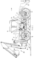
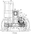
- the machine illustrated in Figures 1 to 8 can be used as a telescopic material handler (for pallet lifting), a loader (for loading), and a backhoe (for digging). It has a chassis comprising a rigid longitudinal frame 1 extending along the whole of the length of the body of the machine.
- the frame 1 is of substantially constant width and its centre-line is in the same vertical plane 2 as the centre-line of the machine.
- the frame 1 is wedge-shaped : its height increases, at a constant gradient, from the front to an intermediate point 3, from where the rear portion 4 of the frame rises more steeply.
- the width of the longitudinal frame 1 is 22.5% of the overall transverse width of the transverse frame 6.
- Front and rear axles 11,12 are mounted on the frame 1 for oscillating motion through a range limited to ⁇ 10° about an axis parallel to the centre-line of the frame 1 and lying in the 13,14 of equal size, steered by means of hydraulic piston-and-cylinder devices 16,17.
- the extreme positions of the wheels 13,14 are indicated in chain-dotted line in Figures 1 to 6.
- the front and rear wheels 13,14 are drivable via final drive units 18,19.
- a telescopic boom 21, having three sections, is pivotally mounted on brackets 22 fixed to the rear portion 4 of the chassis frame 1.
- the extremity 23 of the boom 21 is fitted with pallet lifting forks 24 ( Figure 7) or a loader bucket 26 ( Figure 8) or some other handling device.
- Figure 7 shows the operating range of the boom 21.
- the telescopic boom 21 will normally be retracted before it is moved from a low elevation to a high elevation.
- the centre-line of the boom 21 lies in the vertical plane 2 and it is pivotable by means of a hydraulic piston-and-cylinder device (not shown), connected between the chassis frame 1 and the first section of the boom. At its highest elevation the extremity 23 of the retracted boom is between the front and rear axles 11,12.
- the rear of the chassis frame 1 carries a pair of telescopic stabilisers 27 and a frame 28 for mounting a conventional backhoe 29 which is pivotable about a vertical axis 31 between a working position ( Figures 1, 2, and 8) and a stowed position ( Figure 8).
- the axis 31 is offset from the plane 2 in the opposite direction to the cab 8, to allow space for stowage of the backhoe 29 and to enhance visibility from the cab 8 when working with the backhoe 29.
- the backhoe could, if required, be mounted at another position across the frame 28.
- Figure 8 shows the operating range of the shovel 32 of the backhoe 29, the stabilisers 27 being in engagement with the ground.
- each of the front and rear axles 11,12 is provided, in order to take account of the different requirements during operation with the boom 21 and operation with the backhoe 29.
- the axles are linked to the chassis frame 1 by hydraulic piston-and-cylinder devices (not shown) serving as means for controlling the oscillating motion of the respective axles.
- Automatic actuating means (not shown), comprising detectors and valves, are provided to operate the piston-and-cylinder devices selectively, depending on whether the boom or the backhoe is being used.
- the actuating means which automatically operate the piston-and-cylinder devices so that, on the one hand, the front axle 11 is free to oscillate throughout its range of ⁇ 10° and, on the other hand, the rear axle 12 is locked in a position in which the chassis is transversely level (the stabilisers 27 engaging the ground to assist in keeping the chassis level).
- the actuating means which automatically operates the piston-and-cylinder devices so that, on the one hand, the oscillating motion of the front axle 11 relative to the chassis is continuously controlled (in response to the output of a transverse inclinometer on the chassis) to level the chassis transversely and, on the other hand, the rear axle 12 is free to oscillate throughout its range of ⁇ 10°.
- the actuating means automatically locks the rear axle or controls its oscillation so as to tend to keep the chassis transversely horizontal.
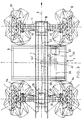
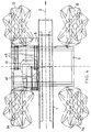
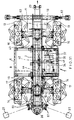
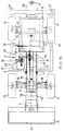
- the side-mounted drive arrangement 7, which is covered by a bonnet 33 that does not obstruct the operator's view to the front and rear, comprises a longitudinally arranged diesel engine 34 connected by means of a torque converter 36 to a gearbox 37.
- the median plane 38 of the engine and gearbox is tilted (as shown in Figures 5 and 6) at an angle of 10° to the vertical, so as to bring the gearbox output closer to the central plane 2.
- the gearbox output is connected by means of a Cardan shaft (axis 39) to a transfer box 41 mid-way along the engine/transmission arrangement 7 and mid-way between the axles 11,12.
- the power take-off or output (axis 42) of the transfer box 41 lies beneath the longitudinal frame 1 and close to the central plane 2.
- the power take-off is connected by means of respective Cardan shafts (axes 43,44) to the final drive units 18,19.
- the cab 8 is mounted on the chassis by means of a parallelogram mechanism, comprising two pairs of front arms 46 and a pair of rear arms 47, allowing the cab 8 to be moved (without rotation) from a first (lower, forward) position between the front and rear axles 11,12 (see Figures 1, 4, and 5, full line, and Figure 2, broken line) to a second (upper, rearward) position above the rear axle 12 (see Figures 2 and 6, full line).
- the cab 8 contains controls (including a steering wheel 48) at the front for operating with the boom 21 and controls (not shown) at the rear for operating with the backhoe 29.
- An operator's seat 49 is rotatable (turning circle 51 indicated in Figure 4) to allow the operator to face forwards or backwards.
- the position of an operator's eye is indicated at 52 in each of Figures 2, 5, and 6, showing that the machine provides good visibility for all the operations it is designed to carry out.
- a one or two-section boom will normally be sufficient.
- the boom may be pivotally mounted at a position between the front and rear of the longitudinal frame 1, in which case the cab may be mounted centrally of the width of the machine, above the rear part of the longitudinal frame 1.
- Digging equipment other than a backhoe may be mounted on the rear of the machine, or omitted.
- Three-mode selectable steering four wheel, crab, or front wheel may be provided.
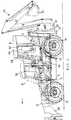
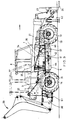
- FIG. 9 A modified embodiment of the machine is shown in Figures 9 to 13. Similar parts are given the same reference numerals.
- the rear of the chassis frame 1 has oblique brackets 61 for mounting the stabilisers 27; the backhoe pivot axis lies on the centre-line of the frame 1.
- the frame 1 carries a pair of telescopic stabilisers 62.
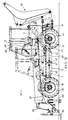
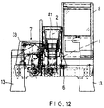
- FIG. 13 and 14 differs from those described above in that the boom is replaced by a loading bucket 71 pivotally mounted on the front ends of a pair of arms 72 whose rear ends are mounted for pivoting about an axis 73 on side plates 74 fixed to the longitudinal chassis frame 1.
- the cab 8 is fixed on top of the frame 1, being centrally positioned with respect to the width of the machine, near the rear of the chassis.
- the loader arms 72 are raised and lowered by a hydraulic piston-and-cylinder device 76.
- the bucket 71 is connected by a linkage 77 to one end of a piston-and-cylinder device 78 whose other end is pivoted to one of the side plates 74, for controlling the bucket.
- Various positions of the arms 72, linkage 77, and bucket 71 are shown in Figure 14. It will be appreciated that, in comparison with conventinal loaders, this machine provides the advantages of improved forward and rearward visibility and an improved linkage arrangement.
Description
Claims (20)
- A material handling machine comprising: a chassis comprising a rigid longitudinal frame (1); an operator's cab (8) mounted on the chassis; material handling means (21) pivotally mounted on the chassis; a front axle (11) and a rear axle (12) mounted on the chassis; wheels (13,14) mounted on the axles (11,12); a drive arrangement (7) mounted on the chassis, at one side of the longitudinal frame (1), between the front and rear axles (11,12), the drive arrangement (7) comprising an engine (34) and a mechanically driven transmission (37,41) kinematically connected to the engine and having a power output (42) substantially mid-way along the drive arrangement (7); final drive units (18,19) on the respective front and rear axles (11,12), for driving the wheels (13,14); and shafts (43,44) kinematically connecting the power output (42) to the final drive units (18,19); characterised in that the engine (34) has a longitudinal extending median plane (38) which is tilted at an angle of substantially 10° to the vertical, so as to bring an output of the mechanically driven transmission (37, 41) closer to the central plane (2) of the machine.
- A machine according to claim 1, including means (28) for mounting a backhoe or other digging equipment at the rear.
- A machine according to claim 1 or claim 2, in which the cab (8) is mounted for movement between a first position in which the region in front of the machine is more easily visible to the operator and a second position in which the region to the rear of the machine is more easily visible.
- A machine as claimed in claim 3, in which the first and second positions are forward and rearward positions.
- A machine as claimed in claim 3 or 4, in which one of the positions is higher than the other.
- A machine as claimed in any of claims 3 to 5, in which one of the positions is mid-way along the machine.
- A machine as claimed in any of claims 3 to 6, in which the cab (8) contains first controls for operations in front of the machine and second controls for operations to the rear of the machine, the first and second controls being respectively at the front and rear of the cab in both of its said positions.
- A machine as claimed in any preceding claim, in which the cab (8) is mounted at the opposite side of the longitudinal frame (1) with respect to the drive arrangement (7).
- A machine as claimed in any preceding claim, in which the power output (4) of the drive arrangement (7) is offset from, a longitudinal centre-line of the drive arrangement towards a longitudinal centre-line of the machine.
- A machine as claimed in claim 9, in which the power output (42) is directly below the longitudinal frame (1).
- A machine as claimed in any preceding claim, in which the power output (42) is substantially mid-way between the front and rear axles (11,12).
- A machine as claimed in any preceding claim, in which the width of the longitudinal frame (1) is less than 25% of the overall width of the machine, excluding the wheels (13,14).
- A machine as claimed in any preceding claim, in which the height of the longitudinal frame (1) increases progressively from a front portion to a rear portion of the frame.
- A machine as claimed in claim 13, in which the height increases at a substantially constant rate from the front to an intermediate portion and at a higher rate from the intermediate portion to the rear of the frame (1).
- A machine as claimed in any preceding claim, in which the front axle (11) and the rear axle (12) are each mounted on the chassis for oscillating motion about an axis parallel to a longitudinal centre-line of the machine, further comprising first means for controlling the oscillating motion of the front axle (11), second means for controlling the oscillating motion of the rear axle (12), and actuating means for selectively operating the said first and second means independently of each other.
- A machine as claimed in claim 15, in which the actuating means has a first mode of operation in which the front axle (11) is free to oscillate through a limited range and the rear axle (12) is prevented from oscillating, for the purpose of working with digging equipment mounted at the rear, and a second mode of operation in which the oscillating motion of the front axle (11) is continuously controlled to level the chassis and the rear axle (12) is free to oscillate through a limited range, for the purpose of working with the material handling means (21).
- A machine as claimed in claim 16, in which the actuating means prevent the rear axle (12) from oscillating when the material handling means (21) reaches a given elevation.
- A machine as claimed in any preceding claim, in which the material handling means comprises a boom (21) extending forwards above the longitudinal frame (1) from a pivotal mounting (22) on the chassis.
- A machine as claimed in any of claims 1 to 17, in which the material handling means comprises a pair of arms (72) having rear ends pivotally mounted on the chassis on respective sides of the longitudinal frame (1), and a loading bucket (71) carried by front ends of the arms (72).
- A machine as claimed in claim 19, in which the cab (8) is centrally positioned with respect to the width of the machine and is mounted near the rear of the chassis.
Applications Claiming Priority (2)
| Application Number | Priority Date | Filing Date | Title |
|---|---|---|---|
| GB9213894 | 1992-06-30 | ||
| GB9213894A GB2268155B (en) | 1992-06-30 | 1992-06-30 | Material handling machine |
Publications (3)
| Publication Number | Publication Date |
|---|---|
| EP0577388A2 EP0577388A2 (en) | 1994-01-05 |
| EP0577388A3 EP0577388A3 (en) | 1994-03-30 |
| EP0577388B1 true EP0577388B1 (en) | 1998-01-21 |
Family
ID=10717964
Family Applications (1)
| Application Number | Title | Priority Date | Filing Date |
|---|---|---|---|
| EP93305075A Expired - Lifetime EP0577388B1 (en) | 1992-06-30 | 1993-06-29 | Material handling machine |
Country Status (5)
| Country | Link |
|---|---|
| US (2) | US5618156A (en) |
| EP (1) | EP0577388B1 (en) |
| DE (2) | DE69316465T2 (en) |
| ES (1) | ES2111131T3 (en) |
| GB (5) | GB2292932B (en) |
Cited By (7)
| Publication number | Priority date | Publication date | Assignee | Title |
|---|---|---|---|---|
| GB2289656A (en) * | 1994-05-16 | 1995-11-29 | Artix Ltd | Drive arrangement for a material handling vehicle |
| US5931255A (en) * | 1997-05-09 | 1999-08-03 | Caterpillar Inc. | Power transfer arrangement for a machine |
| US5944130A (en) * | 1997-11-04 | 1999-08-31 | Caterpillar Inc. | Trunnion mounted drive train arrangement |
| AU743652B2 (en) * | 1998-08-04 | 2002-01-31 | Ingersoll-Rand Company | System for frame leveling and stabilizing a forklift |
| US6390764B1 (en) | 1998-09-09 | 2002-05-21 | Merlo Spa Industria Metalmeccanica | Vehicle operable as both a lifting machine and an agricultural tractor |
| GB2369810A (en) * | 2000-12-09 | 2002-06-12 | Caterpillar Inc | Engine cooling arrangement in a work machine with an extensible arm |
| EP0976878B1 (en) * | 1998-07-25 | 2003-11-12 | J.C. Bamford Excavators Limited | Load handling apparatus |
Families Citing this family (44)
| Publication number | Priority date | Publication date | Assignee | Title |
|---|---|---|---|---|
| DE701963T1 (en) † | 1994-09-14 | 1996-12-12 | Manitou Bf | Motor pallet truck with telescopic arm |
| WO1997046478A1 (en) * | 1996-06-05 | 1997-12-11 | New Holland Uk Limited | Telescopic handler |
| FR2750972B1 (en) * | 1996-07-12 | 1998-10-02 | Fdi Sambron | HANDLING TROLLEY PROVIDED WITH A SECURITY SYSTEM TO AVOID ITS ACCIDENTAL TIP |
| GB9616239D0 (en) * | 1996-08-01 | 1996-09-11 | J T C Heard & Son | Mobile materials handling machines |
| WO1998032928A1 (en) * | 1997-01-28 | 1998-07-30 | Manitou Bf S.A. | Improvements to tractor shovels |
| FR2759662B1 (en) * | 1997-02-20 | 1999-04-23 | Fdi Sambron | LIFT TRUCK, LIFT TRUCK COMPRISING SUCH A CHASSIS, AND METHOD FOR MANUFACTURING SUCH A LIFT |
| US6439827B1 (en) * | 1997-07-08 | 2002-08-27 | J C Bamford Excavators Limited | Load handling vehicle |
| GB2334015B (en) * | 1998-02-10 | 2001-05-30 | Frank Roger Bowden | Base structure for a mobile access platform |
| FR2775246B1 (en) * | 1998-02-20 | 2000-04-07 | Manitou Bf | AUTOMOTIVE VEHICLE WITH TELESCOPIC CHARGER ARM |
| US6152253A (en) * | 1998-04-28 | 2000-11-28 | Gehl Company | Drive train system for a construction-type vehicle |
| IT1303973B1 (en) * | 1998-11-20 | 2001-03-01 | New Holland Italia Spa | VEHICLE EQUIPPED WITH TELESCOPIC LIFT ARM. |
| GB2344809B (en) * | 1998-12-16 | 2002-10-02 | Bamford Excavators Ltd | Earth moving apparatus |
| FR2788759B1 (en) | 1999-01-27 | 2001-03-23 | Sambron | DEVICE FOR CONTROLLING THE MOVEMENT OF A CARRIER STRUCTURE OF A ROLLING MACHINE AND A ROLLING MACHINE INCORPORATING THE SAME |
| GB9921800D0 (en) | 1999-09-16 | 1999-11-17 | Bamford Excavators Ltd | Material -handling vehicle |
| US6409457B1 (en) * | 1999-10-15 | 2002-06-25 | George Korycan | Work vehicle |
| ITBO20000572A1 (en) * | 2000-10-03 | 2002-04-03 | New Holland Italia Spa | EARTH MOVING MACHINE |
| US6863144B2 (en) | 2000-12-08 | 2005-03-08 | Clark Equipment Company | Selectable control parameters on power machine |
| US6425453B1 (en) | 2000-12-08 | 2002-07-30 | Clark Equipment Company | Transmission on all wheel steer power machine |
| US6854554B2 (en) | 2000-12-15 | 2005-02-15 | Clark Equipment Company | Joystick steering on power machine with filtered steering input |
| JP2002362174A (en) * | 2001-04-03 | 2002-12-18 | Komatsu Ltd | Wheel type running work vehicle |
| US6904994B2 (en) * | 2001-11-16 | 2005-06-14 | Caterpillar Inc | Horizontal transmission and oil system for telehandlers |
| GB2389155B (en) * | 2002-03-28 | 2005-12-07 | Jcb Transmissions | Material handling vehicle transmission |
| EP1362824B1 (en) * | 2002-05-15 | 2006-03-15 | Komatsu Utility Europe S.p.A. | Lifting vehicle with a telescopic lifting arm |
| KR20040027090A (en) * | 2002-09-27 | 2004-04-01 | 주일환 | Loader having Back-Hoe apparatus |
| GB2393708B (en) * | 2002-10-01 | 2005-11-30 | Bamford Excavators Ltd | Excavating and loading machine |
| ITTO20021068A1 (en) * | 2002-12-06 | 2004-06-07 | Fiat Kobelco Construction Machinery S P A | VEHICLE ON WHEELS WITH AN OSCILLATING AXLE AROUND A LONGITUDINAL AXIS. |
| FR2849009B1 (en) * | 2002-12-18 | 2005-12-30 | Modules Associes | SEMI-INDUSTRIAL CARRIER, WITH VARIABLE RANGE, FOR THE HANDLING OF MATERIALS |
| DE10305182A1 (en) * | 2003-02-08 | 2004-08-19 | Zf Friedrichshafen Ag | Axial transfer box gearing for work machine is arranged with motor/gearing unit so as not to form a rigidly connected unit for a narrower construction |
| GB2401851A (en) * | 2003-05-20 | 2004-11-24 | Bamford Excavators Ltd | Load handling machine with working arm between front axle and cab |
| DE102004018644A1 (en) * | 2004-04-16 | 2005-11-03 | Liebherr-Werk Nenzing Gmbh, Nenzing | Teleladers, especially reachstackers |
| US7540685B2 (en) | 2005-04-11 | 2009-06-02 | Caterpillar Paving Products Inc. | Movable operator station for a machine |
| US7602050B2 (en) * | 2005-07-18 | 2009-10-13 | Qualcomm Incorporated | Integrated circuit packaging |
| DE102006017516A1 (en) | 2006-04-13 | 2007-10-18 | Bomag Gmbh | Construction machine with articulated chassis |
| US20080022657A1 (en) * | 2006-07-28 | 2008-01-31 | Caterpillar Inc. | Power source thermal management and emissions reduction system |
| DE202007005756U1 (en) | 2007-04-19 | 2008-08-28 | Wirtgen Gmbh | Self-propelled construction machine |
| CA2702060C (en) * | 2007-10-08 | 2013-02-19 | Custom Chassis, Inc. | Multipurpose utility vehicle |
| NL2002125C2 (en) * | 2008-07-14 | 2010-01-18 | Hudson Bay Holding B V | Mobile device. |
| CN101413279B (en) * | 2008-11-29 | 2011-06-08 | 湖南山河智能机械股份有限公司 | Electromechanical integrated digging loader and control method thereof |
| KR101029376B1 (en) * | 2010-10-11 | 2011-04-15 | 대호 (주) | Tractor |
| DE102014219104A1 (en) * | 2014-09-23 | 2016-03-24 | Zf Friedrichshafen Ag | Powertrain for a vehicle |
| FR3043997B1 (en) * | 2015-11-24 | 2018-07-27 | Manitou Bf | HANDLING VEHICLE |
| JP6971773B2 (en) | 2017-10-20 | 2021-11-24 | 株式会社小松製作所 | Work vehicle cab, work vehicle and wheel loader |
| IT201900007197A1 (en) | 2019-05-24 | 2020-11-24 | Scaip S P A | MACHINE, IN THE FORM OF A SELF-PROPELLED SCREEN, FOR THE BURIING OF PIPELINES |
| US11247885B2 (en) | 2020-03-06 | 2022-02-15 | Oshkosh Corporation | Lift device with deployable operator station |
Citations (3)
| Publication number | Priority date | Publication date | Assignee | Title |
|---|---|---|---|---|
| USRE30021E (en) * | 1973-05-21 | 1979-06-05 | Loed Corporation | Material handling machine |
| EP0433244A1 (en) * | 1989-12-15 | 1991-06-19 | MANITOU COSTRUZIONI INDUSTRIALI S.r.l. | A mobile elevator with backhoe |
| CA2009968A1 (en) * | 1990-02-13 | 1991-08-13 | Giovanni Bentivoglio | Boom operated fork truck |
Family Cites Families (32)
| Publication number | Priority date | Publication date | Assignee | Title |
|---|---|---|---|---|
| US1066072A (en) * | 1912-08-20 | 1913-07-01 | Alphons Bouas | Motor-vehicle. |
| US1246116A (en) * | 1917-03-22 | 1917-11-13 | Adolf Kroeter | Automobile propelling and controlling mechanism. |
| US1331197A (en) * | 1918-05-09 | 1920-02-17 | George E Hazlett | Motor-vehicle |
| US2257772A (en) * | 1932-04-07 | 1941-10-07 | Austin M Wolf | Motor vehicle propulsion |
| GB517282A (en) * | 1938-07-15 | 1940-01-25 | Alvis Ltd | Improvements relating to motor-vehicle chassis |
| GB727917A (en) * | 1951-10-11 | 1955-04-13 | Daimler Benz Ag | Improvements in motor vehicles |
| GB763437A (en) * | 1952-10-21 | 1956-12-12 | Rover Co Ltd | Road vehicle power transmission systems |
| US3883153A (en) * | 1973-06-25 | 1975-05-13 | Bhupindar Singh | Apparatus for suppressing spring action between the wheel mounts and frame of a vehicle |
| SE440733B (en) * | 1973-12-07 | 1985-08-19 | Sten Ove Hammarstrand | AXEL SWITCHING SYSTEM FOR TERRAIN VEHICLES |
| US3967744A (en) * | 1975-02-18 | 1976-07-06 | Clark Equipment Company | Extensible reach load lifting mechanism |
| FR2376782A2 (en) * | 1976-02-10 | 1978-08-04 | Bidon Jacques | TRACTOR VEHICLE, ESPECIALLY FOR AGRICULTURAL USE |
| US4087009A (en) * | 1976-04-01 | 1978-05-02 | Massey-Ferguson Inc. | Backhoe frame |
| DE2625679C2 (en) * | 1976-06-08 | 1981-08-27 | Liebherr-Hydraulikbagger Gmbh, 7951 Kirchdorf | Construction machinery, especially excavators |
| DE2739537A1 (en) * | 1976-09-03 | 1978-03-09 | Loed Corp | Pivoted lifting fork on telescopic jib - has drive rotating fork sideways about two separate pivoting axes |
| US4135597A (en) * | 1977-12-29 | 1979-01-23 | Allis-Chalmers Corporation | Chassis oscillation control on an articulated vehicle |
| US4227670A (en) * | 1978-05-25 | 1980-10-14 | International Harvester Company | Pivotable seat support |
| DE3024650A1 (en) * | 1980-06-30 | 1982-02-25 | Claas Ohg, 4834 Harsewinkel | SELF-DRIVING AGRICULTURAL MULTI-PURPOSE VEHICLE WITH ADJUSTABLE DRIVER'S CAB |
| GB2081656A (en) * | 1980-08-06 | 1982-02-24 | Caswell Graham Anwyl Penson | A motorised vehicle |
| FR2530605B1 (en) * | 1982-07-22 | 1986-06-20 | Laigneau Andre | OPERATING CABIN WITH VARIABLE POSITION TO EQUIP AN AGRICULTURAL TRACTOR |
| GB8308088D0 (en) * | 1983-03-24 | 1983-05-05 | Coles Cranes Ltd | Mobile cranes |
| GB8418624D0 (en) * | 1984-07-20 | 1984-08-22 | Mcconnel F W Ltd | Handling/working vehicle |
| JPH0689680B2 (en) * | 1985-10-11 | 1994-11-09 | 日産自動車株式会社 | Vehicle Traction Control Device |
| US4805720A (en) * | 1986-02-27 | 1989-02-21 | Clenet Alain J M | Vehicle drivetrain |
| IT212207Z2 (en) * | 1987-07-27 | 1989-07-04 | Merlo Ind Metalmecc | TELESCOPIC ARM FORKLIFT |
| US4869337A (en) * | 1987-10-15 | 1989-09-26 | Clark Equipment Company | Backhoe creep lever mechanism for an excavating vehicle |
| DE8804637U1 (en) * | 1988-04-08 | 1988-05-19 | Gebr. Steinbock Baumaschinen-Vertriebsgesellschaft Mbh, 6718 Gruenstadt, De | |
| GB8808778D0 (en) * | 1988-04-14 | 1988-05-18 | Bamford Excavators Ltd | Vehicle |
| GB2218891B (en) * | 1988-05-23 | 1992-05-27 | Kubota Ltd | Device for attaching working machine to vehicle |
| JPH0372123A (en) * | 1989-08-11 | 1991-03-27 | Hitachi Constr Mach Co Ltd | Operator's cab of working machine |
| US5052512A (en) * | 1990-08-14 | 1991-10-01 | Ford New Holland, Inc. | Reversible control level linkage |
| GB2250246B (en) * | 1990-11-28 | 1994-07-13 | Rover Group | A wheeled motor vehicle |
| GB2291384A (en) * | 1994-07-15 | 1996-01-24 | Bamford Excavators Ltd | Material-handling vehicle with a loader arm and transverse engine |
-
1992
- 1992-06-30 GB GB9522196A patent/GB2292932B/en not_active Expired - Fee Related
- 1992-06-30 GB GB9522194A patent/GB2292930B/en not_active Expired - Fee Related
- 1992-06-30 GB GB9522193A patent/GB2292929A/en not_active Withdrawn
- 1992-06-30 GB GB9522195A patent/GB2292931B/en not_active Expired - Fee Related
- 1992-06-30 GB GB9213894A patent/GB2268155B/en not_active Expired - Fee Related
-
1993
- 1993-06-29 EP EP93305075A patent/EP0577388B1/en not_active Expired - Lifetime
- 1993-06-29 ES ES93305075T patent/ES2111131T3/en not_active Expired - Lifetime
- 1993-06-29 DE DE69316465T patent/DE69316465T2/en not_active Expired - Fee Related
- 1993-06-29 DE DE0577388T patent/DE577388T1/en active Pending
-
1995
- 1995-09-29 US US08/537,070 patent/US5618156A/en not_active Expired - Fee Related
-
1996
- 1996-12-12 US US08/766,202 patent/US5727921A/en not_active Expired - Fee Related
Patent Citations (3)
| Publication number | Priority date | Publication date | Assignee | Title |
|---|---|---|---|---|
| USRE30021E (en) * | 1973-05-21 | 1979-06-05 | Loed Corporation | Material handling machine |
| EP0433244A1 (en) * | 1989-12-15 | 1991-06-19 | MANITOU COSTRUZIONI INDUSTRIALI S.r.l. | A mobile elevator with backhoe |
| CA2009968A1 (en) * | 1990-02-13 | 1991-08-13 | Giovanni Bentivoglio | Boom operated fork truck |
Cited By (10)
| Publication number | Priority date | Publication date | Assignee | Title |
|---|---|---|---|---|
| GB2289656A (en) * | 1994-05-16 | 1995-11-29 | Artix Ltd | Drive arrangement for a material handling vehicle |
| GB2289656B (en) * | 1994-05-16 | 1997-08-06 | Artix Ltd | Material handling machine |
| US5707202A (en) * | 1994-05-16 | 1998-01-13 | Caterpillar Inc. | Material handling machine |
| US5931255A (en) * | 1997-05-09 | 1999-08-03 | Caterpillar Inc. | Power transfer arrangement for a machine |
| US5944130A (en) * | 1997-11-04 | 1999-08-31 | Caterpillar Inc. | Trunnion mounted drive train arrangement |
| EP0976878B1 (en) * | 1998-07-25 | 2003-11-12 | J.C. Bamford Excavators Limited | Load handling apparatus |
| AU743652B2 (en) * | 1998-08-04 | 2002-01-31 | Ingersoll-Rand Company | System for frame leveling and stabilizing a forklift |
| US6390764B1 (en) | 1998-09-09 | 2002-05-21 | Merlo Spa Industria Metalmeccanica | Vehicle operable as both a lifting machine and an agricultural tractor |
| GB2369810A (en) * | 2000-12-09 | 2002-06-12 | Caterpillar Inc | Engine cooling arrangement in a work machine with an extensible arm |
| GB2369810B (en) * | 2000-12-09 | 2004-07-14 | Caterpillar Inc | Work machine arrangement |
Also Published As
| Publication number | Publication date |
|---|---|
| US5727921A (en) | 1998-03-17 |
| GB2268155A (en) | 1994-01-05 |
| EP0577388A3 (en) | 1994-03-30 |
| GB2292930A (en) | 1996-03-13 |
| GB9522194D0 (en) | 1996-01-03 |
| GB2292931A (en) | 1996-03-13 |
| GB2292932A (en) | 1996-03-13 |
| GB9522195D0 (en) | 1996-01-03 |
| EP0577388A2 (en) | 1994-01-05 |
| GB2292929A (en) | 1996-03-13 |
| GB2292931B (en) | 1996-10-02 |
| GB2292930B (en) | 1996-10-02 |
| GB9522196D0 (en) | 1996-01-03 |
| ES2111131T3 (en) | 1998-03-01 |
| GB9213894D0 (en) | 1992-08-12 |
| GB2268155B (en) | 1996-10-02 |
| DE577388T1 (en) | 1994-06-16 |
| GB2292932B (en) | 1996-10-02 |
| DE69316465T2 (en) | 1998-08-27 |
| GB9522193D0 (en) | 1996-01-03 |
| US5618156A (en) | 1997-04-08 |
| DE69316465D1 (en) | 1998-02-26 |
Similar Documents
| Publication | Publication Date | Title |
|---|---|---|
| EP0577388B1 (en) | Material handling machine | |
| CA1161798A (en) | Hydraulic excavator | |
| ES2203053T3 (en) | OPERABLE VEHICLE AS A LIFTING MACHINE AND AGRICULTURAL TRACTOR. | |
| US6171050B1 (en) | Load arm assembly for a skid steer loader | |
| EP1947249B1 (en) | Common pivot and support member for an attachment interface of a loader | |
| US20070240928A1 (en) | Compact construction vehicle with improved mobility | |
| US6772544B2 (en) | Wheeled work vehicle | |
| US10731321B1 (en) | Compact articulated-steering loader | |
| US9850640B2 (en) | Working machine | |
| KR20160052388A (en) | Working machine | |
| EP2280122B1 (en) | Vertical lift arm device | |
| GB2161784A (en) | Handling or working vehicle | |
| US3674162A (en) | Rough terrain vehicle | |
| US4431363A (en) | Articulated material handling machine | |
| US4750628A (en) | Control system for multi-purpose utility vehicle | |
| US3237790A (en) | Articulated four-wheel drive earthworking vehicle | |
| CN113348283B (en) | Mechanical self-leveling lifting arm structure for power machinery, especially mini loader | |
| US5037236A (en) | Stone-laying machine | |
| EP0413735A1 (en) | Material handling machine | |
| JPH02120132A (en) | Multipurpose farm working vehicle | |
| EP0003655B1 (en) | Tractors and fittings therefor | |
| US20240100971A1 (en) | Work Vehicle | |
| RU2044673C1 (en) | Multi-purpose self-propelled chassis | |
| RU2046887C1 (en) | Motor grader | |
| US20040262069A1 (en) | Load handling machine |
Legal Events
| Date | Code | Title | Description |
|---|---|---|---|
| PUAI | Public reference made under article 153(3) epc to a published international application that has entered the european phase |
Free format text: ORIGINAL CODE: 0009012 |
|
| AK | Designated contracting states |
Kind code of ref document: A2 Designated state(s): DE ES FR GB IT SE |
|
| PUAL | Search report despatched |
Free format text: ORIGINAL CODE: 0009013 |
|
| ITCL | It: translation for ep claims filed |
Representative=s name: BUGNION |
|
| EL | Fr: translation of claims filed | ||
| AK | Designated contracting states |
Kind code of ref document: A3 Designated state(s): DE ES FR GB IT SE |
|
| DET | De: translation of patent claims | ||
| RAP1 | Party data changed (applicant data changed or rights of an application transferred) |
Owner name: CATERPILLAR INC. |
|
| 17P | Request for examination filed |
Effective date: 19940926 |
|
| 17Q | First examination report despatched |
Effective date: 19960524 |
|
| GRAG | Despatch of communication of intention to grant |
Free format text: ORIGINAL CODE: EPIDOS AGRA |
|
| GRAG | Despatch of communication of intention to grant |
Free format text: ORIGINAL CODE: EPIDOS AGRA |
|
| GRAH | Despatch of communication of intention to grant a patent |
Free format text: ORIGINAL CODE: EPIDOS IGRA |
|
| GRAH | Despatch of communication of intention to grant a patent |
Free format text: ORIGINAL CODE: EPIDOS IGRA |
|
| GRAA | (expected) grant |
Free format text: ORIGINAL CODE: 0009210 |
|
| AK | Designated contracting states |
Kind code of ref document: B1 Designated state(s): DE ES FR GB IT SE |
|
| REF | Corresponds to: |
Ref document number: 69316465 Country of ref document: DE Date of ref document: 19980226 |
|
| REG | Reference to a national code |
Ref country code: ES Ref legal event code: FG2A Ref document number: 2111131 Country of ref document: ES Kind code of ref document: T3 |
|
| ITF | It: translation for a ep patent filed |
Owner name: JACOBACCI & PERANI S.P.A. |
|
| ET | Fr: translation filed | ||
| PLBE | No opposition filed within time limit |
Free format text: ORIGINAL CODE: 0009261 |
|
| STAA | Information on the status of an ep patent application or granted ep patent |
Free format text: STATUS: NO OPPOSITION FILED WITHIN TIME LIMIT |
|
| 26N | No opposition filed | ||
| REG | Reference to a national code |
Ref country code: GB Ref legal event code: IF02 |
|
| PGFP | Annual fee paid to national office [announced via postgrant information from national office to epo] |
Ref country code: SE Payment date: 20020604 Year of fee payment: 10 |
|
| PGFP | Annual fee paid to national office [announced via postgrant information from national office to epo] |
Ref country code: ES Payment date: 20020613 Year of fee payment: 10 |
|
| PG25 | Lapsed in a contracting state [announced via postgrant information from national office to epo] |
Ref country code: SE Free format text: LAPSE BECAUSE OF NON-PAYMENT OF DUE FEES Effective date: 20030630 Ref country code: ES Free format text: LAPSE BECAUSE OF NON-PAYMENT OF DUE FEES Effective date: 20030630 |
|
| EUG | Se: european patent has lapsed | ||
| REG | Reference to a national code |
Ref country code: ES Ref legal event code: FD2A Effective date: 20030630 |
|
| PG25 | Lapsed in a contracting state [announced via postgrant information from national office to epo] |
Ref country code: IT Free format text: LAPSE BECAUSE OF NON-PAYMENT OF DUE FEES;WARNING: LAPSES OF ITALIAN PATENTS WITH EFFECTIVE DATE BEFORE 2007 MAY HAVE OCCURRED AT ANY TIME BEFORE 2007. THE CORRECT EFFECTIVE DATE MAY BE DIFFERENT FROM THE ONE RECORDED. Effective date: 20050629 |
|
| PGFP | Annual fee paid to national office [announced via postgrant information from national office to epo] |
Ref country code: DE Payment date: 20070629 Year of fee payment: 15 |
|
| PGFP | Annual fee paid to national office [announced via postgrant information from national office to epo] |
Ref country code: GB Payment date: 20070511 Year of fee payment: 15 |
|
| PGFP | Annual fee paid to national office [announced via postgrant information from national office to epo] |
Ref country code: FR Payment date: 20070605 Year of fee payment: 15 |
|
| GBPC | Gb: european patent ceased through non-payment of renewal fee |
Effective date: 20080629 |
|
| REG | Reference to a national code |
Ref country code: FR Ref legal event code: ST Effective date: 20090228 |
|
| PG25 | Lapsed in a contracting state [announced via postgrant information from national office to epo] |
Ref country code: DE Free format text: LAPSE BECAUSE OF NON-PAYMENT OF DUE FEES Effective date: 20090101 |
|
| PG25 | Lapsed in a contracting state [announced via postgrant information from national office to epo] |
Ref country code: GB Free format text: LAPSE BECAUSE OF NON-PAYMENT OF DUE FEES Effective date: 20080629 |
|
| PG25 | Lapsed in a contracting state [announced via postgrant information from national office to epo] |
Ref country code: FR Free format text: LAPSE BECAUSE OF NON-PAYMENT OF DUE FEES Effective date: 20080630 |